US4418770A - Process for retrieving a coring barrel comprising two tubes and retrieving device for such a process - Google Patents
Process for retrieving a coring barrel comprising two tubes and retrieving device for such a process Download PDFInfo
- Publication number
- US4418770A US4418770A US06/322,130 US32213081A US4418770A US 4418770 A US4418770 A US 4418770A US 32213081 A US32213081 A US 32213081A US 4418770 A US4418770 A US 4418770A
- Authority
- US
- United States
- Prior art keywords
- tube
- boring
- retrieving
- outer tube
- cylindrical body
- Prior art date
- Legal status (The legal status is an assumption and is not a legal conclusion. Google has not performed a legal analysis and makes no representation as to the accuracy of the status listed.)
- Expired - Fee Related
Links
- 238000000034 method Methods 0.000 title claims description 13
- 230000001174 ascending effect Effects 0.000 claims abstract description 25
- 238000007789 sealing Methods 0.000 claims abstract description 21
- 230000005484 gravity Effects 0.000 claims abstract description 6
- 239000007788 liquid Substances 0.000 claims description 39
- 230000002093 peripheral effect Effects 0.000 claims description 27
- 238000005553 drilling Methods 0.000 claims description 20
- 238000002347 injection Methods 0.000 claims description 5
- 239000007924 injection Substances 0.000 claims description 5
- XLYOFNOQVPJJNP-UHFFFAOYSA-N water Substances O XLYOFNOQVPJJNP-UHFFFAOYSA-N 0.000 claims description 2
- 230000002706 hydrostatic effect Effects 0.000 claims 1
- 230000001105 regulatory effect Effects 0.000 claims 1
- 239000012530 fluid Substances 0.000 abstract 1
- 230000000717 retained effect Effects 0.000 abstract 1
- 230000000630 rising effect Effects 0.000 description 3
- 230000000295 complement effect Effects 0.000 description 1
- 239000003208 petroleum Substances 0.000 description 1
- 238000011084 recovery Methods 0.000 description 1
- 230000035939 shock Effects 0.000 description 1
- 239000000725 suspension Substances 0.000 description 1
- 238000004804 winding Methods 0.000 description 1
Images


Classifications
-
- E—FIXED CONSTRUCTIONS
- E21—EARTH OR ROCK DRILLING; MINING
- E21B—EARTH OR ROCK DRILLING; OBTAINING OIL, GAS, WATER, SOLUBLE OR MELTABLE MATERIALS OR A SLURRY OF MINERALS FROM WELLS
- E21B23/00—Apparatus for displacing, setting, locking, releasing or removing tools, packers or the like in boreholes or wells
- E21B23/08—Introducing or running tools by fluid pressure, e.g. through-the-flow-line tool systems
-
- E—FIXED CONSTRUCTIONS
- E21—EARTH OR ROCK DRILLING; MINING
- E21B—EARTH OR ROCK DRILLING; OBTAINING OIL, GAS, WATER, SOLUBLE OR MELTABLE MATERIALS OR A SLURRY OF MINERALS FROM WELLS
- E21B23/00—Apparatus for displacing, setting, locking, releasing or removing tools, packers or the like in boreholes or wells
- E21B23/04—Apparatus for displacing, setting, locking, releasing or removing tools, packers or the like in boreholes or wells operated by fluid means, e.g. actuated by explosion
-
- E—FIXED CONSTRUCTIONS
- E21—EARTH OR ROCK DRILLING; MINING
- E21B—EARTH OR ROCK DRILLING; OBTAINING OIL, GAS, WATER, SOLUBLE OR MELTABLE MATERIALS OR A SLURRY OF MINERALS FROM WELLS
- E21B25/00—Apparatus for obtaining or removing undisturbed cores, e.g. core barrels or core extractors
- E21B25/02—Apparatus for obtaining or removing undisturbed cores, e.g. core barrels or core extractors the core receiver being insertable into, or removable from, the borehole without withdrawing the drilling pipe
Definitions
- This invention relates to a process for retrieving a coring barrel comprising two tubes, used in the presence of a boring liquid, as well as a retrieving device for such a process.
- the process according to the invention allows particularly the retrieval or recovery, during a rising or ascending boring, of a coring apparatus or barrel comprising an inner tube which may slide within an outer tube.
- the inner tube comprises a set of hollow rods provided, at one end, with a core extracting sleeve and, at the other end, with a head.
- the outer tube comprises a set of hollow rods, provided at one end with a drilling crown.
- the head of the inner tube has a suspension stop and locking means engaged, in the boring position, in an annular notch for locking the outer tube, the inner tube having, from its upper end to its lower end, within the outer tube, a passage for enabling the flow of the boring liquid toward the drilling crown.
- the device according to the invention is specifically adapted for said process for retrieving the core barrel during a rising boring, said device being however also useful for retrieving the same core barrel during a substantially horizontal or descending boring.
- Double tube coring barrels are presently widely used in all types of boring, for example in descending borings for mine, petroleum or geothermal prospection, or in horizontal or ascending borings for drillings in underground working.
- a known coring apparatus comprises two coaxial tubes, in which the inner tube may be locked into the outer tube and may be unlocked and brought back to the surface through the outer tube, by means of a cable, a retrieving element called “overshot” and an auxiliary winch, whereas the outer tube carrying the drilling crown remains in the drilled hole.
- the coring is effected, both in a descending boring and in an ascending boring, in the presence of boring liquid injected by means of a pump toward the drilling or boring crown carried by the free end of the inner tube or set of hollow rods, through an annular space between the inner set of rods (inner tube) and the outer set of rods (outer tube).
- Said boring liquid is usually water.
- the pump must be sufficiently powerful for overcoming the important level differences between said pump and the bottom of the boring well.
- the inner tube of the coring barrel can only be retrieved, in even the case of an ascending boring, by means of a cable by rather difficult operations.
- the pump must again be connected to the outer tube and the retrieving element must hydraulically be pushed toward the inner tube of the coring barrel, the retrieving element being automatically latched to a head of the inner tube of the coring barrel.
- the inner tube must be unlocked by means of a cable, upon pulling said cable. Then by winding the cable on a winch, one must bring back the inner tube from the bore hole by controlling the descent speed of said inner tube.
- An object of the invention is to avoid the drawbacks of the known techniques for retrieving a coring barrel in a rising or ascending boring.
- the invention relates to a process for retrieving, in an ascending or descending boring, a double tube coring barrel used in the presence of a boring liquid.
- a particularly interesting feature of the process according to the invention is that the retrieving head itself can be used for pushing, under hydraulic pressure, the inner tube toward the end of the outer tube, which carries the drilling crown.
- This invention also relates to a device for retrieving, during an ascending boring, a double tube coring barrel used in the presence of a boring liquid and comprising, within an outer tube consisting of a set of hollow rods and provided at one end with a boring crown, an inner tube equipped, at the end corresponding to said end, with a core extracting sleeve or core lifter and, at its other end, with a retrieving head and which is provided with locking means engaged, in the drilling position, in a locking annular notch or recess of the outer tube, the inner tube forming, from its upper end to its lower end, within the outer tube, a passage for the circulation of the drilling liquid toward the drilling crown.
- said retrieving device comprises means for latching it to a device for unlocking the inner tube of the coring barrel, as well as hydraulic sealing means with respect to the outer tube, said latching means and said hydraulic sealing means cooperating with each other and possibly with means belonging to the outer tube for allowing, when an ascending boring is effected, the boring liquid to flow toward the drilling crown and for causing the retrieving head to be hydraulically sealed with respect to the outer tube, when the injection of the boring liquid is interrupted.
- the retrieving head comprises a cylindrical body which may slide within the outer tube, means for latching this cylindrical body to an unlocking device allowing the sliding of the cylindrical body between two end positions with respect to the unlocking device, as well as at least one peripheral joint carried by the cylindrical body so that the retrieving head may form a sealing piston in the bore of the outer tube, whereby, in an ascending boring, the retrieving head is first in an upper position, in which the joint or joints of the retrieving head is or are maintained in front of a peripheral recess of the outer tube, so as to permit to the boring liquid to flow towards the drilling crown, during the boring, and moves into a lower second position, in which said head forms a sealing piston in the outer tube, when the injection of the drilling liquid is interrupted.
- the retrieving head of the coring barrel comprises a cylindrical body provided with at least one peripheral joint and with a latching device which may slide with respect to the unlocking device and having a bore connecting the opposite ends of the cylindrical body, located on both sides of the peripheral joint or joints, another sliding joint which may close the part of said bore located on the opposite side with respect to the sliding latching means, a tube provided with a base plate or flange having one or more openings connecting its inner bore to the outer space and adapted for being attached to the cylindrical body on the opposite side of the sliding latching means while maintaining said other sliding joint in its position, the plate tube extending axially about an axial rod passing through the base plate and provided, at its end located inside the plate tube, with a sealing piece capable of closing the bore and, at its end located outside the plate tube, with a frusto-conical hook, a helical spring surrounding the axial rod and bearing against the plate of the plate tube and against said sealing piece.
- a significant advantage of such a retrieving head is that it can be used equally with said other sliding joint for retrieving the coring barrel during an ascending boring, without overshot, nor cable, and without said other sliding joint for retrieving the coring barrel, in the usual way, with an overshot and a cable, during a substantially horizontal or descending boring.
- each of the peripheral joints is mounted on the cylindrical body downstream the unlocking device and consists of a removable ring surrounding the cylindrical body, the plate tube being threaded so that it is screwed on the cylindrical body thereby maintaining the ring against a peripheral stop of the cylindrical body, whereas the axial rod carrying said sealing piece is provided with a stop cooperating with the plate of the plate tube so as to compress said other sliding joint against the connecting bore, when the plate tube is screwed on the cylindrical body.
- the means for latching the cylindrical body to the unlocking device of the inner tube of the coring barrel allows the retrieving head to slide with respect to the unlocking device between two end positions
- a sliding joint is used for maintaining the bore of the cylindrical body closed even when a pressure is exerted on the closure from the inside of the bore.
- said sliding joint is compressed in the closing position of the bore, when the plate tube is screwed on the cylindrical body.
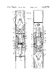
- FIG. 1 is a section of a first embodiment of a device for retrieving a coring barrel according to this invention, used in an ascending boring, the locking means of the inner tube of the coring barrel being engaged, in the boring position, in an annular locking notch and the cylindrical body of the retrieving head being in an upper position, in which the joints of the retrieving head are maintained in front of a peripheral recess of the outer tube, so as to allow the drilling liquid to flow;
- FIG. 2 is a section similar to that of FIG. 1 of the device for retrieving the coring barrel shown in FIG. 1, used in an ascending boring, the means for locking the inner tube of the coring barrel being engaged in the annular locking notch, but the cylindrical body of the retrieving head being in a lower position in which said head forms a sealing piston in the outer tube, when the injection of boring liquid is interrupted;
- FIG. 3 is a section similar to that of FIGS. 1 and 2 showing the device for retrieving the coring barrel, when used in an ascending boring, the means for locking the inner tube of the coring barrel having been unlocked;
- FIG. 4 is a section of another embodiment of a device for retrieving a coring barrel, when used in an ascending boring, said device being however utilizable in a substantially horizontal or descending boring;
- FIG. 5 is a section similar to that of FIG. 2 of the device for retrieving a coring barrel shown in FIG. 4;
- FIG. 6 is a section of the device for retrieving a coring barrel shown in FIGS. 4 and 5, when used in a descending boring, the means for locking the inner tube of the coring barrel being engaged, in the boring position, in an annular locking notch and the cylindrical body of the retrieving head being in a lower position, the joints of the retrieving head being maintained in front of a peripheral recess of the outer tube, so as to allow the circulation of the boring liquid, and
- FIG. 7 is a section similar to that of FIG. 6 showing the coring barrel represented in FIGS. 4 to 6 when it is retrieved, during a descending boring, by means of an overshot and a cable.
- FIGS. 1 to 3 show a first embodiment of the device for retrieving the inner tube of a coring barrel according to this invention.
- the coring barrel used in an ascending boring comprises essentially an inner tube 2 which may slide within an outer tube 1 and is provided with a retrieving head 3 according to a first embodiment of the invention.
- the inner tube 2 and the retrieving head 3 are locked (FIGS. 1 and 2) in the outer tube 1, by means of a locking device 4 fastening in a peripheral groove 31 of the outer tube, by the feet 32 of a latch 33, outwardly urged by a spring 34.
- a sliding device 7 consisting of a tubular latch carrier 35 integral with the inner tube and of an unlatching slide 36 which carries an unlatching pin 37 and may slide in the tubular latch carrier 35.
- the pin 37 removes thus the feed 32 of the latch 33 from the latching groove 31.
- the retrieving head 3 is connected to said slide 36 by means of a latching device 8 consisting of a pin 40 fixed to the slide 36 and introduced in an elongated recess 41 in the end of the retrieving head 3.
- said retrieving head 3 consists of a cylindrical body 10 comprising two cylindrical elements 42 and 43 screwed on each other with a ring 25 therebetween, said ring 25 being provided with peripheral joints 6 capable of forming a sealing joint with respect to the bore of the outer tube 1.
- the retrieving head 3 may moreover comprise a frusto-conical hook 23 which allows, for example, the hooking of a retrieving piece provided with a cable, if necessary.
- the device for retrieving the inner tube of the coring barrel according to the invention is used as follows:
- the inner tube 2 of the coring barrel is latched in the outer tube 1, the retrieving head 3 being in the position shown in FIG. 1.
- the retrieving head 3 is maintained in said upper position by the hydraulic pressure exerted by the boring liquid which is sent, under pressure, toward the boring crown.
- peripheral joints 6 are thus maintained in front of a peripheral recess 5 in the bore of the outer tube 1, so as to allow the boring liquid to pass.
- the retrieving head 3 moves by gravity toward a lower position shown in FIG. 2, so that the peripheral joints 6 sealingly contact the bore of the outer tube and the back end of the elongated recess 41 bears on the pin 40 of the slide 36.
- the unlatching pin 37 thus acts onto the latch 33, so as to remove the feet 32 from the groove 31 and to release the inner tube 2.
- the inner tube 2 starts then to descend in the outer tube 1 (see FIG. 3) under the influence of its own weight and of the depression created by the boring liquid column.
- the device descends together with the liquid column.
- the descent speed of the liquid column is controlled by adjusting the flow of the discharge valve. This adjustment allows a smooth retrieval of cores, shocks which might affect the quality of these cores being avoided.
- FIGS. 4 and 5 show a second embodiment of the device for retrieving coring barrels according to the invention, in an ascending boring.
- the operation of the device is exactly the same as that of the device described with reference to FIGS. 1 to 3.
- the retrieving device is however different, since this device can be used both for retrieving the coring barrel without overshot or cable in an ascending boring and for retrieving the coring barrel in a horizontal or descending boring.
- This device comprises a cylindrical body 10 and a tube 16 having a base plate or flange 17, said tube 16 being screwed (26) on the cylindrical body, a ring 25 provided with peripheral joints 6 being compressed between the body 10 and the tube 16.
- the cylindrical body 10 is connected to the unlatching slide 36 by means of a latching device 8 and is provided with a bore 11 connecting its two ends 12, 13.
- said bore 11 connecting the two ends 12, 13 of the cylindrical body, located on both sides of the peripheral joints 6, is closed by a sliding joint 14.
- This sliding joint 14 is maintained in place in the cavity of the tube 16 by an axial rod 20 extending through said tube 16, one end 22 of which bears against said sliding joint 14 and a stop 28 of the axial rod 20 bearing, on the other side, against the base plate or flange 17 of the tube 16.
- the device In this use position, the device has thus exactly the same function as the device described above with reference to FIGS. 1 to 3. This means that, during the boring, the boring liquid may flow through a peripheral recess in the bore of the outer tube 1 (FIG. 4) and that, when the hydraulic pressure of the boring liquid is interrupted, the device descends toward the lower position, in which the peripheral joints 6 sealingly contact the bore of the outer tube (FIG. 5).
- FIGS. 6 and 7 illustrate the use of the device according to the invention for the retrieval of an inner tube of the coring barrel in the usual manner with an overshot 29 and a cable 30, in a descending boring.
- the device according to the invention is used without the sliding closing joint 14 for the bore 11 in the cylindrical body 10.
- the inner tube 2 of the coring barrel is latched in the outer tube by the locking device 4.
- the retrievind head 3 drives the sliding hooking device 8 in a lower position, due to the hydraulic pressure of the boring liquid and to the weight of the retrieving head.
- the boring liquid can thus flow toward the boring crown through the peripheral recess 5 of the bore of the outer tube.
- an overshot 29 is lowered into the outer tube 1 by means of a cable 30.
- the grip 50 moves the axial rod 20 against the spring 24.
- the rod 20 then bears against the base plate 17 of the tube 16 through its stop 28, so that the retrieving head 3 is driven upwardly until it reaches a position wherein the peripheral joints 6 sealingly contact the bore of the outer tube 1.
- the boring liquid column located above the retrieving head 3 and the peripheral sealing joints 6 thereof may flow through the openings 18 of the tube 16 and the bore 11 of the cylindrical body 10, when the inner tube is driven upwardly.
Landscapes
- Geology (AREA)
- Life Sciences & Earth Sciences (AREA)
- Engineering & Computer Science (AREA)
- Mining & Mineral Resources (AREA)
- Environmental & Geological Engineering (AREA)
- Fluid Mechanics (AREA)
- Physics & Mathematics (AREA)
- General Life Sciences & Earth Sciences (AREA)
- Geochemistry & Mineralogy (AREA)
- Earth Drilling (AREA)
- Investigation Of Foundation Soil And Reinforcement Of Foundation Soil By Compacting Or Drainage (AREA)
- Sampling And Sample Adjustment (AREA)
- Transition And Organic Metals Composition Catalysts For Addition Polymerization (AREA)
Applications Claiming Priority (2)
| Application Number | Priority Date | Filing Date | Title |
|---|---|---|---|
| EP80201101A EP0052672B1 (de) | 1980-11-21 | 1980-11-21 | Verfahren zum Herausziehen eines im Bohrloch auswechselbaren Bohrkernbehälters und ein hierfür vorgesehener Fangkopf |
| EP80201101.5 | 1980-11-21 |
Publications (1)
| Publication Number | Publication Date |
|---|---|
| US4418770A true US4418770A (en) | 1983-12-06 |
Family
ID=8187053
Family Applications (1)
| Application Number | Title | Priority Date | Filing Date |
|---|---|---|---|
| US06/322,130 Expired - Fee Related US4418770A (en) | 1980-11-21 | 1981-11-17 | Process for retrieving a coring barrel comprising two tubes and retrieving device for such a process |
Country Status (5)
| Country | Link |
|---|---|
| US (1) | US4418770A (de) |
| EP (1) | EP0052672B1 (de) |
| AT (1) | ATE12288T1 (de) |
| DE (1) | DE3070343D1 (de) |
| ZA (1) | ZA818048B (de) |
Cited By (20)
| Publication number | Priority date | Publication date | Assignee | Title |
|---|---|---|---|---|
| US4512422A (en) * | 1983-06-28 | 1985-04-23 | Rondel Knisley | Apparatus for drilling oil and gas wells and a torque arrestor associated therewith |
| US4736613A (en) * | 1986-05-05 | 1988-04-12 | Westinghouse Electric Corp. | Nuclear reactor fuel assembly mixing vane repair apparatus |
| US4832901A (en) * | 1986-05-05 | 1989-05-23 | Westinghouse Electric Corp. | Nuclear reactor fuel assembly mixing vane repair method |
| US4832138A (en) * | 1987-05-13 | 1989-05-23 | Diamant Boart S.A. | Device to control the locking of a boring corer |
| US5267620A (en) * | 1991-05-01 | 1993-12-07 | Longyear Company | Drilling latch apparatus |
| US6196757B1 (en) * | 1997-12-09 | 2001-03-06 | Kongsberg Offshore As | Anchoring mechanism for a guide post |
| US20100012383A1 (en) * | 2007-03-03 | 2010-01-21 | Longyear Tm, Inc. | High productivity core drilling system |
| US20110079435A1 (en) * | 2009-10-07 | 2011-04-07 | Longyear Tm, Inc. | Driven latch mechanism |
| US20110079436A1 (en) * | 2009-10-07 | 2011-04-07 | Longyear Tm, Inc. | Core drilling tools with retractably lockable driven latch mechanisms |
| US20110083901A1 (en) * | 2009-10-07 | 2011-04-14 | Longyear Tm, Inc. | Core drilling tools with external fluid pathways |
| US20110198131A1 (en) * | 2008-04-22 | 2011-08-18 | Longyear Tm, Inc. | Core barrel assemblies with braking devices |
| US20120074722A1 (en) * | 2009-02-25 | 2012-03-29 | 2Ic Australia Pty Ltd. | Head Assembly |
| US20130032410A1 (en) * | 2011-08-01 | 2013-02-07 | Martin Jolicoeur | Core barrel assembly including a valve |
| US20150123415A1 (en) * | 2012-06-13 | 2015-05-07 | Areva Gmbh | Gripper |
| CN105089530A (zh) * | 2015-08-12 | 2015-11-25 | 新疆华隆油田科技股份有限公司 | 可洗井防返吐控制阀装置 |
| CN105156057A (zh) * | 2015-07-01 | 2015-12-16 | 吉林大学 | 一种带有到位报信的绳索取心定位悬挂机构 |
| US9359847B2 (en) | 2007-03-03 | 2016-06-07 | Longyear Tm, Inc. | High productivity core drilling system |
| US9399898B2 (en) | 2009-10-07 | 2016-07-26 | Longyear Tm, Inc. | Core drilling tools with retractably lockable driven latch mechanisms |
| US9528337B2 (en) | 2009-10-07 | 2016-12-27 | Longyear Tm, Inc. | Up-hole bushing and core barrel head assembly comprising same |
| CN112377131A (zh) * | 2020-10-29 | 2021-02-19 | 中煤科工集团西安研究院有限公司 | 一种近水平定向连续取芯装置与方法 |
Citations (4)
| Publication number | Priority date | Publication date | Assignee | Title |
|---|---|---|---|---|
| US2656151A (en) * | 1949-08-10 | 1953-10-20 | Herbert T Miller | Removable drop-in type back-pressure valve for drill strings |
| US2857138A (en) * | 1954-07-02 | 1958-10-21 | Longyear E J Co | Core barrel |
| US3340939A (en) * | 1965-08-27 | 1967-09-12 | Longyear E J Co | Core lifter apparatus |
| US4187919A (en) * | 1977-05-03 | 1980-02-12 | Diamant Boart | Cable-type core barrel |
Family Cites Families (4)
| Publication number | Priority date | Publication date | Assignee | Title |
|---|---|---|---|---|
| US3704755A (en) * | 1971-06-18 | 1972-12-05 | Boyles Ind Ltd | Retrieving and lowering system for a core barrel |
| US3704756A (en) * | 1971-07-19 | 1972-12-05 | Boyles Ind Ltd | Apparatus for lowering and retrieving a core barrel |
| US3777826A (en) * | 1971-09-15 | 1973-12-11 | Boyles Ind Ltd | Fluid responsive core barrel system |
| FR2359273A1 (fr) * | 1976-07-20 | 1978-02-17 | Diamant Boart Sa | Appareil carottier du type a cable |
-
1980
- 1980-11-21 EP EP80201101A patent/EP0052672B1/de not_active Expired
- 1980-11-21 AT AT80201101T patent/ATE12288T1/de active
- 1980-11-21 DE DE8080201101T patent/DE3070343D1/de not_active Expired
-
1981
- 1981-11-17 US US06/322,130 patent/US4418770A/en not_active Expired - Fee Related
- 1981-11-20 ZA ZA818048A patent/ZA818048B/xx unknown
Patent Citations (4)
| Publication number | Priority date | Publication date | Assignee | Title |
|---|---|---|---|---|
| US2656151A (en) * | 1949-08-10 | 1953-10-20 | Herbert T Miller | Removable drop-in type back-pressure valve for drill strings |
| US2857138A (en) * | 1954-07-02 | 1958-10-21 | Longyear E J Co | Core barrel |
| US3340939A (en) * | 1965-08-27 | 1967-09-12 | Longyear E J Co | Core lifter apparatus |
| US4187919A (en) * | 1977-05-03 | 1980-02-12 | Diamant Boart | Cable-type core barrel |
Cited By (48)
| Publication number | Priority date | Publication date | Assignee | Title |
|---|---|---|---|---|
| US4512422A (en) * | 1983-06-28 | 1985-04-23 | Rondel Knisley | Apparatus for drilling oil and gas wells and a torque arrestor associated therewith |
| US4736613A (en) * | 1986-05-05 | 1988-04-12 | Westinghouse Electric Corp. | Nuclear reactor fuel assembly mixing vane repair apparatus |
| US4832901A (en) * | 1986-05-05 | 1989-05-23 | Westinghouse Electric Corp. | Nuclear reactor fuel assembly mixing vane repair method |
| US4832138A (en) * | 1987-05-13 | 1989-05-23 | Diamant Boart S.A. | Device to control the locking of a boring corer |
| US5267620A (en) * | 1991-05-01 | 1993-12-07 | Longyear Company | Drilling latch apparatus |
| US6196757B1 (en) * | 1997-12-09 | 2001-03-06 | Kongsberg Offshore As | Anchoring mechanism for a guide post |
| US9359847B2 (en) | 2007-03-03 | 2016-06-07 | Longyear Tm, Inc. | High productivity core drilling system |
| US20100012383A1 (en) * | 2007-03-03 | 2010-01-21 | Longyear Tm, Inc. | High productivity core drilling system |
| US8333255B2 (en) | 2007-03-03 | 2012-12-18 | Longyear Tm, Inc. | High productivity core drilling system |
| US8051924B2 (en) | 2008-04-22 | 2011-11-08 | Longyear Tm, Inc. | Methods of braking core barrel assemblies |
| US20110198131A1 (en) * | 2008-04-22 | 2011-08-18 | Longyear Tm, Inc. | Core barrel assemblies with braking devices |
| US20110198127A1 (en) * | 2008-04-22 | 2011-08-18 | Longyear Tm, Inc. | Methods of braking core barrel assemblies |
| US8051925B2 (en) | 2008-04-22 | 2011-11-08 | Longyear Tm, Inc. | Core barrel assemblies with braking devices |
| EP2401472A4 (de) * | 2009-02-25 | 2017-06-28 | Imdex Global B.V. | Kopfeinheit |
| AU2010217182B2 (en) * | 2009-02-25 | 2017-03-16 | Reflex Instruments Asia Pacific Pty Ltd | Head assembly |
| US10030460B2 (en) | 2009-02-25 | 2018-07-24 | Reflex Instruments Asia Pacific Pty Ltd | Head assembly |
| AU2017204087B2 (en) * | 2009-02-25 | 2018-08-02 | Reflex Instruments Asia Pacific Pty Ltd | Head Assembly |
| US20120074722A1 (en) * | 2009-02-25 | 2012-03-29 | 2Ic Australia Pty Ltd. | Head Assembly |
| US9103178B2 (en) * | 2009-02-25 | 2015-08-11 | 2Ic Australia Pty Ltd. | Head assembly |
| EP3358125A1 (de) * | 2009-02-25 | 2018-08-08 | Imdex Global B.V. | Kopfanordnung |
| US20140332279A1 (en) * | 2009-10-07 | 2014-11-13 | Longyear Tm, Inc. | Driven latch mechanism |
| US9689222B2 (en) | 2009-10-07 | 2017-06-27 | Longyear Tm, Inc. | Core drilling tools with external fluid pathways |
| US8794355B2 (en) | 2009-10-07 | 2014-08-05 | Longyear Tm, Inc. | Driven latch mechanism |
| US8869918B2 (en) | 2009-10-07 | 2014-10-28 | Longyear Tm, Inc. | Core drilling tools with external fluid pathways |
| US20110079435A1 (en) * | 2009-10-07 | 2011-04-07 | Longyear Tm, Inc. | Driven latch mechanism |
| US20110079436A1 (en) * | 2009-10-07 | 2011-04-07 | Longyear Tm, Inc. | Core drilling tools with retractably lockable driven latch mechanisms |
| CN102791954A (zh) * | 2009-10-07 | 2012-11-21 | 长年Tm公司 | 从动闩锁机构 |
| US20110083901A1 (en) * | 2009-10-07 | 2011-04-14 | Longyear Tm, Inc. | Core drilling tools with external fluid pathways |
| US8485280B2 (en) | 2009-10-07 | 2013-07-16 | Longyear Tm, Inc. | Core drilling tools with retractably lockable driven latch mechanisms |
| US9528337B2 (en) | 2009-10-07 | 2016-12-27 | Longyear Tm, Inc. | Up-hole bushing and core barrel head assembly comprising same |
| US9234398B2 (en) | 2009-10-07 | 2016-01-12 | Longyear Tm, Inc. | Core drilling tools with retractably lockable driven latch mechanisms |
| CN102791954B (zh) * | 2009-10-07 | 2016-01-20 | 长年Tm公司 | 岩心筒头部组件以及用于取回岩心样本的钻井系统和方法 |
| US9399898B2 (en) | 2009-10-07 | 2016-07-26 | Longyear Tm, Inc. | Core drilling tools with retractably lockable driven latch mechanisms |
| US9328608B2 (en) * | 2009-10-07 | 2016-05-03 | Longyear Tm, Inc. | Driven latch mechanism |
| WO2011044314A3 (en) * | 2009-10-07 | 2011-10-13 | Longyear Tm, Inc. | Driven latch mechanism |
| WO2011084589A2 (en) * | 2009-12-16 | 2011-07-14 | Longyear Tm, Inc. | Core drilling tools with retractably lockable driven latch mechanisms |
| WO2011084589A3 (en) * | 2009-12-16 | 2011-09-29 | Longyear Tm, Inc. | Core drilling tools with retractably lockable driven latch mechanisms |
| AU2012209032B2 (en) * | 2011-08-01 | 2016-07-28 | Groupe Fordia Inc | Core barrel assembly including a valve |
| US20130032410A1 (en) * | 2011-08-01 | 2013-02-07 | Martin Jolicoeur | Core barrel assembly including a valve |
| US9151129B2 (en) * | 2011-08-01 | 2015-10-06 | Groupe Fordia Inc. | Core barrel assembly including a valve |
| US20150123415A1 (en) * | 2012-06-13 | 2015-05-07 | Areva Gmbh | Gripper |
| US9242381B2 (en) * | 2012-06-13 | 2016-01-26 | Areva Gmbh | Gripper |
| CN105156057B (zh) * | 2015-07-01 | 2017-08-08 | 吉林大学 | 一种带有到位报信的绳索取心定位悬挂机构 |
| CN105156057A (zh) * | 2015-07-01 | 2015-12-16 | 吉林大学 | 一种带有到位报信的绳索取心定位悬挂机构 |
| CN105089530B (zh) * | 2015-08-12 | 2017-11-14 | 新疆华隆油田科技股份有限公司 | 可洗井防返吐控制阀装置 |
| CN105089530A (zh) * | 2015-08-12 | 2015-11-25 | 新疆华隆油田科技股份有限公司 | 可洗井防返吐控制阀装置 |
| CN112377131A (zh) * | 2020-10-29 | 2021-02-19 | 中煤科工集团西安研究院有限公司 | 一种近水平定向连续取芯装置与方法 |
| CN112377131B (zh) * | 2020-10-29 | 2022-09-06 | 中煤科工集团西安研究院有限公司 | 一种近水平定向连续取芯装置与方法 |
Also Published As
| Publication number | Publication date |
|---|---|
| EP0052672A1 (de) | 1982-06-02 |
| EP0052672B1 (de) | 1985-03-20 |
| ZA818048B (en) | 1982-11-24 |
| DE3070343D1 (en) | 1985-04-25 |
| ATE12288T1 (de) | 1985-04-15 |
Similar Documents
| Publication | Publication Date | Title |
|---|---|---|
| US4418770A (en) | Process for retrieving a coring barrel comprising two tubes and retrieving device for such a process | |
| EP1795698B1 (de) | Fülleinrichtung für Röhrenstrang | |
| RU2282708C1 (ru) | Глубинный гидродомкрат для ликвидации прихватов | |
| US6564885B2 (en) | Up-hole overshot and safety drilling apparatus | |
| US4161367A (en) | Method and apparatus for completing diverless subsea flowline connections | |
| US3236307A (en) | Method and apparatus for releasing wall-stuck pipe | |
| US9353603B2 (en) | Landing string compensator | |
| US9644439B2 (en) | Core barrel head assembly | |
| US5044442A (en) | Casing hanger running tool using annulus pressure | |
| US4940094A (en) | Method and device to actuate specialized intervention equipment in a drilled well having at least one section highly slanted with respect to a vertical line | |
| US4386656A (en) | Tubing hanger landing and orienting tool | |
| US4502537A (en) | Annular sample chamber, full bore, APR® sampler | |
| US2277989A (en) | Method and apparatus for drilling wells | |
| US4813496A (en) | Drill ahead tool | |
| US2217986A (en) | Well pipe plug | |
| US5947202A (en) | Method and apparatus for engaging an object | |
| US4560004A (en) | Drill pipe tester - pressure balanced | |
| US2865454A (en) | Oil well fishing apparatus and method | |
| US2220554A (en) | Device for recovering cores from boreholes | |
| GB1596782A (en) | Method and apparatus for completing diverless subsea flowline connections | |
| CN115538965A (zh) | 一种压入式绳索取心装置 | |
| US3704755A (en) | Retrieving and lowering system for a core barrel | |
| US3232346A (en) | Production apparatus and method | |
| SU1714092A1 (ru) | Устройство дл создани скважинного гравийного фильтра | |
| SU796401A1 (ru) | Забойный пробоотборник |
Legal Events
| Date | Code | Title | Description |
|---|---|---|---|
| AS | Assignment |
Owner name: SOCIETE ANONYME DIAMANT BOART AVE. DU PONT DE LUT Free format text: ASSIGNMENT OF ASSIGNORS INTEREST.;ASSIGNOR:LAMBOT, HONORE J.;REEL/FRAME:004170/0464 Effective date: 19811109 |
|
| MAFP | Maintenance fee payment |
Free format text: PAYMENT OF MAINTENANCE FEE, 4TH YEAR, PL 96-517 (ORIGINAL EVENT CODE: M170); ENTITY STATUS OF PATENT OWNER: LARGE ENTITY Year of fee payment: 4 |
|
| FEPP | Fee payment procedure |
Free format text: SURCHARGE FOR LATE PAYMENT, PL 96-517 (ORIGINAL EVENT CODE: M176); ENTITY STATUS OF PATENT OWNER: LARGE ENTITY |
|
| MAFP | Maintenance fee payment |
Free format text: PAYMENT OF MAINTENANCE FEE, 8TH YEAR, PL 96-517 (ORIGINAL EVENT CODE: M171); ENTITY STATUS OF PATENT OWNER: LARGE ENTITY Year of fee payment: 8 |
|
| FEPP | Fee payment procedure |
Free format text: MAINTENANCE FEE REMINDER MAILED (ORIGINAL EVENT CODE: REM.); ENTITY STATUS OF PATENT OWNER: LARGE ENTITY |
|
| FEPP | Fee payment procedure |
Free format text: PAYOR NUMBER ASSIGNED (ORIGINAL EVENT CODE: ASPN); ENTITY STATUS OF PATENT OWNER: LARGE ENTITY |
|
| FEPP | Fee payment procedure |
Free format text: MAINTENANCE FEE REMINDER MAILED (ORIGINAL EVENT CODE: REM.); ENTITY STATUS OF PATENT OWNER: LARGE ENTITY |
|
| LAPS | Lapse for failure to pay maintenance fees | ||
| FP | Lapsed due to failure to pay maintenance fee |
Effective date: 19951206 |
|
| STCH | Information on status: patent discontinuation |
Free format text: PATENT EXPIRED DUE TO NONPAYMENT OF MAINTENANCE FEES UNDER 37 CFR 1.362 |