US4736613A - Nuclear reactor fuel assembly mixing vane repair apparatus - Google Patents
Nuclear reactor fuel assembly mixing vane repair apparatus Download PDFInfo
- Publication number
- US4736613A US4736613A US06/859,549 US85954986A US4736613A US 4736613 A US4736613 A US 4736613A US 85954986 A US85954986 A US 85954986A US 4736613 A US4736613 A US 4736613A
- Authority
- US
- United States
- Prior art keywords
- tool
- blades
- elongated member
- mixing vane
- fuel cell
- Prior art date
- Legal status (The legal status is an assumption and is not a legal conclusion. Google has not performed a legal analysis and makes no representation as to the accuracy of the status listed.)
- Expired - Lifetime
Links
Images


Classifications
-
- G—PHYSICS
- G21—NUCLEAR PHYSICS; NUCLEAR ENGINEERING
- G21C—NUCLEAR REACTORS
- G21C3/00—Reactor fuel elements and their assemblies; Selection of substances for use as reactor fuel elements
- G21C3/30—Assemblies of a number of fuel elements in the form of a rigid unit
- G21C3/32—Bundles of parallel pin-, rod-, or tube-shaped fuel elements
- G21C3/334—Assembling, maintenance or repair of the bundles
-
- Y—GENERAL TAGGING OF NEW TECHNOLOGICAL DEVELOPMENTS; GENERAL TAGGING OF CROSS-SECTIONAL TECHNOLOGIES SPANNING OVER SEVERAL SECTIONS OF THE IPC; TECHNICAL SUBJECTS COVERED BY FORMER USPC CROSS-REFERENCE ART COLLECTIONS [XRACs] AND DIGESTS
- Y02—TECHNOLOGIES OR APPLICATIONS FOR MITIGATION OR ADAPTATION AGAINST CLIMATE CHANGE
- Y02E—REDUCTION OF GREENHOUSE GAS [GHG] EMISSIONS, RELATED TO ENERGY GENERATION, TRANSMISSION OR DISTRIBUTION
- Y02E30/00—Energy generation of nuclear origin
- Y02E30/30—Nuclear fission reactors
-
- Y—GENERAL TAGGING OF NEW TECHNOLOGICAL DEVELOPMENTS; GENERAL TAGGING OF CROSS-SECTIONAL TECHNOLOGIES SPANNING OVER SEVERAL SECTIONS OF THE IPC; TECHNICAL SUBJECTS COVERED BY FORMER USPC CROSS-REFERENCE ART COLLECTIONS [XRACs] AND DIGESTS
- Y10—TECHNICAL SUBJECTS COVERED BY FORMER USPC
- Y10T—TECHNICAL SUBJECTS COVERED BY FORMER US CLASSIFICATION
- Y10T29/00—Metal working
- Y10T29/49—Method of mechanical manufacture
- Y10T29/49718—Repairing
- Y10T29/49748—Repairing by shaping, e.g., bending, extruding, turning, etc.
Definitions
- This invention relates to nuclear reactors and, more particularly, to an apparatus and related method for repairing bent mixing vanes found in the fuel assemblies of nuclear, pressurized-water reactors.
- a conventional nuclear, pressurized-water reactor located within a conventional nuclear, pressurized-water reactor is a plurality of parallel fuel rod supporting grids. These grids are made up of a plurality of thin bands or straps arranged in a lattice configuration to form individual fuel cells. Each fuel rod containing nuclear fuel pellets is inserted through a fuel cell within a grid. Each fuel rod is held in a fixed relationship within the fuel cell by a plurality of springs (see, e.g., co-assigned U.S. Pat. No. 3,379,618 issued to Frisch), and punched, metal dimples arranged along the inner faces of each fuel cell. Each fuel rod is supported by being lightly pushed against the dimples via one or more of the springs.
- the grids also include metal fins or "mixing vanes" at the corners thereof, perpendicular to the grid straps, which may lightly abut, but do not mechanically support, the fuel rod. Mixing vanes are intended to disturb fluid flow, i.e., cause a swirling action to improve heat transfer and reduce the potential for hot spot temperatures at the fuel rods.
- the mixing vanes can be damaged, i.e., bent.
- a bent mixing vane interferes with normal fuel rod reinsertion, i.e., exerts bending moment on the fuel rod, thus causing the fuel rod to deflect and bow out of its intended path. Deflection causes the fuel rod to "hang-up" on the first grid below the grid with the bent mixing vane.
- an apparatus and method for straightening bent mixing vanes are desired so that fuel rods can be reliably reinserted.
- a nuclear reactor fuel assembly mixing vane repair apparatus including generally a unique tool and a related tool handling device.
- the tool is made up of an elongated tube with a housing containing two sets of high-strength blades remotely movable between closed and opened positions.
- the tool is inserted into a fuel cell detected as having a grid with a bent mixing vane therein via the tool handling device to a location below the damaged grid with the blades in the closed position.
- the blades are then remotely opened via a cable and rod combination within the apparatus, and the tool is withdrawn.
- a blade abuts the bent mixing vane and bends it back close to its original position. After straightening of the bent mixing vane, the blades are closed and the tool is fully extracted from the fuel cell. Once the tool is fully extracted, the fuel rod can again be reliably inserted into the repaired fuel cell.
- the related method includes the steps of: introducing the apparatus with the blades closed below the damaged grid; opening the blades as the apparatus is withdrawn to abut and straighten the bent mixing vane; closing the blades; and fully extracting the apparatus from the fuel cell.
- FIG. 1 is a partial, cross-sectional view of a typical nuclear reactor, illustrating particularly the fuel assembly
- FIG. 2 is a schematic, elevational view of a fuel assembly, illustrating particularly orientation of the various grids thereof and representative insertion of a fuel rod;
- FIG. 3 is a top, plan view of a conventional grid, illustrating particularly individual fuel cells, each having mixing vanes, springs and/or dimples;
- FIG. 4 is a side, cross-sectional view of a portion of the mixing vane repair apparatus according to the present invention, illustrating particularly orientation of the movable blades within the tool thereof.
- FIG. 4A is an enlarged, side, cross-sectional view of the blade housing and blades shown in FIG. 4.
- FIG. 5 is a front, cross-sectional view of the mixing vane repair apparatus according to the present invention taken along line 5--5 of FIG. 4;
- FIG. 6 is a side, partial cross-sectional view of a portion of the mixing vane repair apparatus according to the present invention, illustrating particularly the tool handling device thereof;
- FIG. 7 is a side, cross-sectional view of a portion of the tool shown in FIGS. 4 and 4A, with the blades deleted;
- FIG. 8 is a side, elevational view of one blade of a pair used with the tool according to the present invention.
- FIG. 9 is a side, elevational view of another blade of a pair used with the tool according to the present invention.
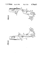
- FIG. 10 is a side view of the mixing vane repair apparatus according to the present invention during use.
- FIG. 1 is a partial, cross-sectional view of a portion of a conventional nuclear, pressurized-water reactor 10, including a vessel 12 enclosing so-called bottom mounted instrumentation 14 (illustrated schematically), and a lower barrel assembly 16.
- the lower barrel assembly 16 includes a generally cylindrical side wall 17 affixed at its lower and upper ends to respective lower and upper core plates 18 and 19.
- Fuel assemblies 20 are positioned in vertically oriented, parallel axial relationship within the lower barrel assembly 16.
- a radiation reflection shield 21 is also mounted interiorly of the cylindrical side walls 17.
- the fuel assembly 20 of FIG. 1 is shown in greater detail in FIG. 2.
- the fuel assembly 20 includes a skeleton 28 made up of parallel grids 30, including relatively thin grids 31 and relatively thick grids 32.
- the height of each relatively thin grid 31 is approximately, 0.56 inches, whereas the height of each relatively thick grid 32 is approximately 21/2 to 3 inches.
- each grid 30 is made up of a lattice of straps 33 oriented perpendicularly to each other (see FIG. 3).
- the grids 30 are connected to vertical supports or thimble tubes 34.
- the skeleton 28 is terminated by a bottom nozzle 38 and a top nozzle 39.
- a fuel rod 36 can be introduced from the top of the skeleton 28 via a conventional rod handling means 37 and inserted sequentially through the grids 30.
- the outer diameter of a fuel rod 36 may be, e.g., 0.36 inch.
- the grid 30 basically includes a plurality of external fuel cells 40 and a plurality of internal fuel cells 41.
- thimble tube openings 48 are formed for receiving the thimble tubes 34 shown in FIG. 2
- Each fuel cell 40, 41 includes at least one mixing vane 42 positioned at the corners thereof.
- Each mixing vane 42 is located at the top of the grid strap 33.
- references numeral 42a indicates the first case where a mixing vane 42 which is damaged, i.e., bent, is located opposite two springs 44.
- Reference numeral 42b indicates the second case where a bent mixing vane 42 is located opposite a spring 44 and a dimple 46.
- reference numeral 42c indicates the third case where a bent mixing vane 42 is located opposite two dimples 46.
- a damaged mixing vane 42 in one grid 30 produces lateral forces which can skew a fuel rod 36 and result in hang-up at the next lower grid 30 during fuel rod 36 reinsertion.
- Tests have indicated that fuel rod 36 hang up usually does not occur with either the first or second cases discussed above, i.e., 42a or 42b, but occurs most often in the third case, i.e., 42c, when the damaged mixing vane 42 is located opposite two dimples 46.
- the object of the present invention is to repair or reform any bent mixing vanes 42 in the internal or external fuel cells 40, 41 which might cause a fuel rod 36 to hang up during reinsertion.
- the present invention satisfies this object by providing a mixing vane repair apparatus 49, including a unique tool 50 having movable blades 52, 54, 56 and 58 and a related tool handling device 51 for operating the tool 50 within the fuel cell 40, 41.
- FIGS. 4 and 4A is a partial crosssectional view of the tool 50.
- the tool 50 is shown with blades 52 and 56, both in the closed (inactive) position by solid lines and in the open (active) position by phantom lines.
- the present invention actually includes four opposing blades 52, 54, 56 and 58, which are described in detail below.
- the tool 50 comprises a tube 60, preferably a 5/16 inch diameter by approximately twelve foot heavy walled, stainless steel tube, including first through fourth sections 60a, 60b, 60c and 60d, respectively.
- Sections 60a and 60c include adjacent,threaded ends 61 and 63, respectively, which are connected via an internally threaded connector 65.
- the fourth section 60d which is a bottom end cap 90 includes an internally threaded portion 92 therein for receiving a corresponding externally threaded portion 86 formed on the opposite end of the third section 60c.
- Sections 60a and 60b of the tool 50 contain an activating rod 62, preferably a 0.093 inch diameter stainless steel rod with brazed on brass bearings 64, spread about two feet apart to prevent buckling.
- the 5/16 diameter of the tube 60 is sufficiently smaller than the exemplary 0.36 inch diameter fuel rod 36 to permit easy insertion of the tool 50 into a fuel cell 40, 41 below a grid 30 which includes a bent mixing vane 42.
- the blades 52, 54, 56 and 58 and tube 60 sizes would be proportionately modified.
- the activating rod 62 contacts a smaller rod 66, preferably 0.06 inch ⁇ 3.75 inch, located in section 60c which is threaded through two rectangular blocks 68 and 70, each having similar construction.
- each block 68, 70 contains two small dowel pins 79 and 81 that slide in slots 76 and 78, respectively, of overlapping blades 52, 56.
- the block 70 similarly receives blades 54 and 58.
- Each blade 52, 54, 56, 58 is oriented 90° relative to adjacent blades.
- both rectangular blocks 68 and 70 move downward 0.06 inches thereby causing the four blades 52, 54, 56 and 58 to swing out of the housing 82, into the open (active) position as shown in FIGS. 4 and 4A.
- the center of gravity of each, blade 52, 54, 56 and 58 is outboard of the pins 79 and 81, thus producing a torque which assists the opening force produced by the rectangular blocks 68 and 70.
- the blades 52, 54, 56 and 58 are completely retracted into the housing 82 so that the tool 50 can be inserted past a grid 30 with a damaged mixing vane 42 and opened therebelow, as also described hereafter.
- each blade 52, 54, 56 and 58 preferably has an approximate 0.39 ⁇ 0.02 inch vertical height on the outside thereof which is necessary so that opposite blades can maintain alignment and contact with the mixing vane 42 and the grid strap 33 as the mixing vane 42 is re-bent to its original unbent (or slightly higher) position.
- the blades 52, 54, 56 and 58 should be hinged overlapping pairs rather than individual blades one above the other.
- the latter construction would be simpler, but the former construction is required due to the short vertical height, e.g., 0.56 inches, of the relatively thin grids 31. That is, in grid 31, the blades 52, 54, and 56, 58 have to occupy the same axial position in order to contact the grid strap 33 and mixing vane 42 simultaneously. If, for example, one blade 52 contacts the mixing vane 42 and the opposite blade 56 in the pair is not in position to carry the reaction force, the 5/16 inch diameter tube 60 would carry some of the force and would deflect excessively. As a result, the mixing vane 42 would not be properly straightened. Accordingly, overlapping blade pairs 52, 56 and 54, 58 are preferred when the grids 30 are relatively thin.
- blades 52, 54, 56 and 58 are secured in the housing 82 by means of the two dowel pins 72 and 74.
- These pins 72, 74 serve as common stabilizing pivots and carry only a small part of the mixing vane 42 straightening force.
- Upper pins 73 and 75 are located in respective blade can slots 87 and 88, each having a locking groove 77 that locks the blades 52, 54, 56 and 58 in the open (active) position shown in FIGS. 4 and 4A.
- the spring 80 pulls the rod 66 upward, kicking the blades 52, 54, 56 and 58 out of the locking groove 77 and rotating them into the housing 82.
- the pins 79 and 81 are received by openings 83 and 85, respectively, and further aid the pivoting motion of the blades.
- a taper 84 of preferably 15° provided on each blade 52, 54, 56 and 58 generates a force which lifts the blades and disengages the locking groove 77. This causes the blades to swing inward, thus minimizing the force exerted on the grid 30.
- FIG. 6 shows the tool handling device 51 to be used with the tool 50.
- the device 51 preferably comprises of an attachment 103, a conduit 102 (preferably thirty feet of one-inch aluminum) and a collet 104.
- the collet 104 clamps to the end plug 106 of the tool 50 shown in FIG. 4.
- the end plug 106 is standard so that the tool can also be handled by any of the conventionally used fuel rod manipulation tools, manual or motorized.
- a pushrod 108 preferably 0.06 inches in diameter, passes through the collet 104 and contacts the activating rod 62 of the tool 50 shown in FIG. 4.
- the means for moving the blades 52, 54, 56 and 58 between the opened and closed positions includes the 0.06 diameter pushrod 108 connected to a plurality of brass weights 112.
- the weights 112 are lifted by the operator remotely pulling a stainless steel cable 114 running through the tool handling device 51.
- Confirmation that a bent mixing vane 42 exists can first be obtained by measuring excessive fuel rod 36 insertion force (force limit trip), removing the fuel rod and then observing the condition of the mixing vane(s) 42 using a conventional quartz fiberscope connected to a TV system (not shown). Once there is verification that a fuel rod 36 cannot be inserted into the fuel cell inspected due to a bent mixing vane(s) 42, the tool 50 is attached to the tool handling device 51 to form the mixing vane repair apparatus 49 according to the present invention. Then a stationary pointer may be clamped to some convenient point on the bridge railing (not shown) of the nuclear reactor and is used as a reference, e.g., against marks made on the tool handling device 51. This keeps the blades 52, 54, 56 and 58 of the tool 50 properly aligned with respect to the grids 30.
- the apparatus 49 is then introduced with the blades 52, 54, 56 and 58 in the closed position into, e.g., the fuel cell 41 to a point just below a grid 320 including the bent mixing vane 42, as shown by "A" in FIG. 10.
- the apparatus 49 is raised until the blades are slightly above the bottom of the damaged grid 30.
- the blades 52, 54, 56 and 58 are then opened by releasing the pulled cable 114, as described above.
- each is positioned in a corner of the fuel cell 41.
- a blade, e.g., 52, is now directly under the bent mixing vane 42.
- load is monitored. The load is increased to twenty-five to thirty pounds as the damaged mixing vane(s) 42 is contacted by the blade 52.
- This load is maintained as the mixing vane is moved through the intermediate position 42' and until it becomes a "straightened” or re-bent mixing vane 42", as shown by "B" in FIG. 10.
- one blade, e.g., 52, of a pair performs the straightening while the other blade 56 of the pair carries the reaction load over to the grid strap 33.
- the pointer on the spent fuel pit bridge rail enables the operator to maintain orientation of the blades 52, 54, 56 and 58 relative to the chosen grid 30.
- the tool 50 is raised until a 30 pound load limit is reached, at which time the mixing vane should be straightened.
- the apparatus 49 is then raised until blades 52, 54, 56 and 58 clear the grid 30. As the apparatus 49 is raised, the blades 52, 54, 56 and 58 should be in the closed position when passing any other grids 30 and the apparatus 49 is fully extracted from the fuel cell 41.
- the fiberscope is used again to inspect the condition of all straightened mixing vanes 42" and verify that the fuel rods 36 can be re-inserted into the fuel cell 40, 41 locations that now have repaired (straightened) mixing vanes 42".
Landscapes
- Physics & Mathematics (AREA)
- Engineering & Computer Science (AREA)
- Plasma & Fusion (AREA)
- General Engineering & Computer Science (AREA)
- High Energy & Nuclear Physics (AREA)
- Monitoring And Testing Of Nuclear Reactors (AREA)
- Mixers Of The Rotary Stirring Type (AREA)
Abstract
Description
Claims (3)
Priority Applications (3)
| Application Number | Priority Date | Filing Date | Title |
|---|---|---|---|
| US06/859,549 US4736613A (en) | 1986-05-05 | 1986-05-05 | Nuclear reactor fuel assembly mixing vane repair apparatus |
| JP62104890A JPH0731274B2 (en) | 1986-05-05 | 1987-04-30 | Method and device for adjusting mixing blades of a grid |
| US07/146,674 US4832901A (en) | 1986-05-05 | 1988-01-21 | Nuclear reactor fuel assembly mixing vane repair method |
Applications Claiming Priority (1)
| Application Number | Priority Date | Filing Date | Title |
|---|---|---|---|
| US06/859,549 US4736613A (en) | 1986-05-05 | 1986-05-05 | Nuclear reactor fuel assembly mixing vane repair apparatus |
Related Child Applications (1)
| Application Number | Title | Priority Date | Filing Date |
|---|---|---|---|
| US07/146,674 Division US4832901A (en) | 1986-05-05 | 1988-01-21 | Nuclear reactor fuel assembly mixing vane repair method |
Publications (1)
| Publication Number | Publication Date |
|---|---|
| US4736613A true US4736613A (en) | 1988-04-12 |
Family
ID=25331186
Family Applications (1)
| Application Number | Title | Priority Date | Filing Date |
|---|---|---|---|
| US06/859,549 Expired - Lifetime US4736613A (en) | 1986-05-05 | 1986-05-05 | Nuclear reactor fuel assembly mixing vane repair apparatus |
Country Status (2)
| Country | Link |
|---|---|
| US (1) | US4736613A (en) |
| JP (1) | JPH0731274B2 (en) |
Cited By (6)
| Publication number | Priority date | Publication date | Assignee | Title |
|---|---|---|---|---|
| US4791801A (en) * | 1987-08-03 | 1988-12-20 | Westinghouse Electric Corp. | Reversible fuel assembly grid tab repair tool |
| US4832901A (en) * | 1986-05-05 | 1989-05-23 | Westinghouse Electric Corp. | Nuclear reactor fuel assembly mixing vane repair method |
| US5032347A (en) * | 1988-12-28 | 1991-07-16 | Framatome | Device and method for straightening the guide fins of the spacer grids of a fuel assembly of a nuclear reactor |
| US5685190A (en) * | 1993-06-25 | 1997-11-11 | Daikin Industries, Ltd. | Expanding mandrel, expanding method and expanding apparatus using the expanding mandrel and heat exchanger with heat exchanging tubes expanded by the expanding method |
| US20050129163A1 (en) * | 2003-12-11 | 2005-06-16 | Pabis George S. | Fuel assembly top nozzle repair sleeve and method for repairing a fuel assembly |
| WO2012039647A1 (en) * | 2010-09-22 | 2012-03-29 | Закрытое Акционерное Общество "Диаконт" | Device for gripping a cluster of fuel assemblies in a nuclear reactor |
Citations (9)
| Publication number | Priority date | Publication date | Assignee | Title |
|---|---|---|---|---|
| US559932A (en) * | 1896-05-12 | Implement for removing curbs or tubes from the ground | ||
| US1445581A (en) * | 1921-08-24 | 1923-02-13 | Joseph F Fullop | Tool for removing well casings and the like |
| US2142017A (en) * | 1932-02-27 | 1938-12-27 | Midland Steel Prod Co | Apparatus for expanding sections of tubing |
| US3152830A (en) * | 1961-01-05 | 1964-10-13 | Atomic Energy Authority Uk | Grab devices |
| US3379618A (en) * | 1965-12-03 | 1968-04-23 | Westinghouse Electric Corp | Fuel arrangement for a nuclear reactor |
| US3719560A (en) * | 1969-04-29 | 1973-03-06 | Westinghouse Electric Corp | Fuel assembly for a nuclear reactor using zirconium alloy clad fuel rods |
| US4244616A (en) * | 1978-02-17 | 1981-01-13 | Framatome | Tool for exchanging and transporting irradiation capsules of a nuclear reactor |
| US4418770A (en) * | 1980-11-21 | 1983-12-06 | Societe Anonyme Diamant Boart | Process for retrieving a coring barrel comprising two tubes and retrieving device for such a process |
| US4427622A (en) * | 1980-09-04 | 1984-01-24 | Kraftwerk Union Aktiengesellschaft | Alignment tool for spacers of nuclear reactor fuel assemblies |
-
1986
- 1986-05-05 US US06/859,549 patent/US4736613A/en not_active Expired - Lifetime
-
1987
- 1987-04-30 JP JP62104890A patent/JPH0731274B2/en not_active Expired - Fee Related
Patent Citations (9)
| Publication number | Priority date | Publication date | Assignee | Title |
|---|---|---|---|---|
| US559932A (en) * | 1896-05-12 | Implement for removing curbs or tubes from the ground | ||
| US1445581A (en) * | 1921-08-24 | 1923-02-13 | Joseph F Fullop | Tool for removing well casings and the like |
| US2142017A (en) * | 1932-02-27 | 1938-12-27 | Midland Steel Prod Co | Apparatus for expanding sections of tubing |
| US3152830A (en) * | 1961-01-05 | 1964-10-13 | Atomic Energy Authority Uk | Grab devices |
| US3379618A (en) * | 1965-12-03 | 1968-04-23 | Westinghouse Electric Corp | Fuel arrangement for a nuclear reactor |
| US3719560A (en) * | 1969-04-29 | 1973-03-06 | Westinghouse Electric Corp | Fuel assembly for a nuclear reactor using zirconium alloy clad fuel rods |
| US4244616A (en) * | 1978-02-17 | 1981-01-13 | Framatome | Tool for exchanging and transporting irradiation capsules of a nuclear reactor |
| US4427622A (en) * | 1980-09-04 | 1984-01-24 | Kraftwerk Union Aktiengesellschaft | Alignment tool for spacers of nuclear reactor fuel assemblies |
| US4418770A (en) * | 1980-11-21 | 1983-12-06 | Societe Anonyme Diamant Boart | Process for retrieving a coring barrel comprising two tubes and retrieving device for such a process |
Cited By (7)
| Publication number | Priority date | Publication date | Assignee | Title |
|---|---|---|---|---|
| US4832901A (en) * | 1986-05-05 | 1989-05-23 | Westinghouse Electric Corp. | Nuclear reactor fuel assembly mixing vane repair method |
| US4791801A (en) * | 1987-08-03 | 1988-12-20 | Westinghouse Electric Corp. | Reversible fuel assembly grid tab repair tool |
| US5032347A (en) * | 1988-12-28 | 1991-07-16 | Framatome | Device and method for straightening the guide fins of the spacer grids of a fuel assembly of a nuclear reactor |
| US5685190A (en) * | 1993-06-25 | 1997-11-11 | Daikin Industries, Ltd. | Expanding mandrel, expanding method and expanding apparatus using the expanding mandrel and heat exchanger with heat exchanging tubes expanded by the expanding method |
| US20050129163A1 (en) * | 2003-12-11 | 2005-06-16 | Pabis George S. | Fuel assembly top nozzle repair sleeve and method for repairing a fuel assembly |
| US7551705B2 (en) * | 2003-12-11 | 2009-06-23 | Areva Np, Inc. | Fuel assembly top nozzle repair sleeve and method for repairing a fuel assembly |
| WO2012039647A1 (en) * | 2010-09-22 | 2012-03-29 | Закрытое Акционерное Общество "Диаконт" | Device for gripping a cluster of fuel assemblies in a nuclear reactor |
Also Published As
| Publication number | Publication date |
|---|---|
| JPH0731274B2 (en) | 1995-04-10 |
| JPS62263496A (en) | 1987-11-16 |
Similar Documents
| Publication | Publication Date | Title |
|---|---|---|
| Penn et al. | CANDU fuel—power ramp performance criteria | |
| JP2008216246A (en) | System for aligning and manipulating fuel rods within a nuclear fuel assembly | |
| US4736613A (en) | Nuclear reactor fuel assembly mixing vane repair apparatus | |
| US4832901A (en) | Nuclear reactor fuel assembly mixing vane repair method | |
| US2930744A (en) | Charge chutes for atomic reactors | |
| JPS5872097A (en) | Nuclear fuel assembly | |
| US3964964A (en) | Identification of failed fuel element | |
| US4788026A (en) | Nuclear fuel assembly grid sleeve/guide thimble bulge orientation gage and inspection method | |
| US4696784A (en) | System for manipulating radioactive fuel rods within a nuclear fuel assembly | |
| US4448744A (en) | Method of loading and/or unloading a nuclear reactor, and support member, especially for the foregoing method | |
| JP3131046B2 (en) | Tool and method for removing a detector thimble from a reactor vessel | |
| US3297541A (en) | Nuclear reactor core structure | |
| JPH07198891A (en) | How to prevent scratches on fuel rods during fuel bundle assembly | |
| US5126098A (en) | Method of straightening a bowed nuclear fuel assembly | |
| JPH0115038B2 (en) | ||
| US6619712B1 (en) | Refueling mast retaining tool for a nuclear reactor | |
| US5032347A (en) | Device and method for straightening the guide fins of the spacer grids of a fuel assembly of a nuclear reactor | |
| JP3247534B2 (en) | Control rod guide tube mounting device for HTGR | |
| US3190806A (en) | Continuously refueled nuclear reactors | |
| US6101231A (en) | Nuclear fuel bundle spacer spring force measurement system | |
| JPH0352595B2 (en) | ||
| JPS5834394A (en) | Guide device of incore remote inspection device | |
| Dolbey | CIGAR: An Automated Inspection System for CANDU Reactor Fuel Channels | |
| Fryer et al. | Identification of failed fuel element | |
| JPH04238297A (en) | Device for guiding insertion of in-reactor instrumentation pipe |
Legal Events
| Date | Code | Title | Description |
|---|---|---|---|
| AS | Assignment |
Owner name: WESTINGHOUSE ELECTRIC CORPORATION, WESTINGHOUSE BU Free format text: ASSIGNMENT OF ASSIGNORS INTEREST.;ASSIGNOR:DAILEY, GEORGE F.;REEL/FRAME:004558/0603 Effective date: 19860424 Owner name: WESTINGHOUSE ELECTRIC CORPORATION,PENNSYLVANIA Free format text: ASSIGNMENT OF ASSIGNORS INTEREST;ASSIGNOR:DAILEY, GEORGE F.;REEL/FRAME:004558/0603 Effective date: 19860424 |
|
| STCF | Information on status: patent grant |
Free format text: PATENTED CASE |
|
| FEPP | Fee payment procedure |
Free format text: PAYOR NUMBER ASSIGNED (ORIGINAL EVENT CODE: ASPN); ENTITY STATUS OF PATENT OWNER: LARGE ENTITY |
|
| FPAY | Fee payment |
Year of fee payment: 4 |
|
| FEPP | Fee payment procedure |
Free format text: PAYER NUMBER DE-ASSIGNED (ORIGINAL EVENT CODE: RMPN); ENTITY STATUS OF PATENT OWNER: LARGE ENTITY Free format text: PAYOR NUMBER ASSIGNED (ORIGINAL EVENT CODE: ASPN); ENTITY STATUS OF PATENT OWNER: LARGE ENTITY |
|
| FEPP | Fee payment procedure |
Free format text: PAYER NUMBER DE-ASSIGNED (ORIGINAL EVENT CODE: RMPN); ENTITY STATUS OF PATENT OWNER: LARGE ENTITY Free format text: PAYOR NUMBER ASSIGNED (ORIGINAL EVENT CODE: ASPN); ENTITY STATUS OF PATENT OWNER: LARGE ENTITY |
|
| FPAY | Fee payment |
Year of fee payment: 8 |
|
| AS | Assignment |
Owner name: WESTINGHOUSE ELECTRIC CO. LLC, PENNSYLVANIA Free format text: ASSIGNMENT OF ASSIGNORS INTEREST;ASSIGNOR:CBS CORPORATION (FORMERLY KNOWN AS WESTINGHOUSE ELECTRIC CORPORATION;REEL/FRAME:010070/0819 Effective date: 19990322 |
|
| FPAY | Fee payment |
Year of fee payment: 12 |