US4412973A - Autonomous simultaneous analysis apparatus and a method of using it - Google Patents
Autonomous simultaneous analysis apparatus and a method of using it Download PDFInfo
- Publication number
- US4412973A US4412973A US06/330,430 US33043081A US4412973A US 4412973 A US4412973 A US 4412973A US 33043081 A US33043081 A US 33043081A US 4412973 A US4412973 A US 4412973A
- Authority
- US
- United States
- Prior art keywords
- reaction
- cells
- liquid
- cell
- orifice
- Prior art date
- Legal status (The legal status is an assumption and is not a legal conclusion. Google has not performed a legal analysis and makes no representation as to the accuracy of the status listed.)
- Expired - Fee Related
Links
Images


Classifications
-
- G—PHYSICS
- G01—MEASURING; TESTING
- G01N—INVESTIGATING OR ANALYSING MATERIALS BY DETERMINING THEIR CHEMICAL OR PHYSICAL PROPERTIES
- G01N21/00—Investigating or analysing materials by the use of optical means, i.e. using sub-millimetre waves, infrared, visible or ultraviolet light
- G01N21/01—Arrangements or apparatus for facilitating the optical investigation
- G01N21/03—Cuvette constructions
- G01N21/07—Centrifugal type cuvettes
-
- B—PERFORMING OPERATIONS; TRANSPORTING
- B04—CENTRIFUGAL APPARATUS OR MACHINES FOR CARRYING-OUT PHYSICAL OR CHEMICAL PROCESSES
- B04B—CENTRIFUGES
- B04B5/00—Other centrifuges
- B04B5/04—Radial chamber apparatus for separating predominantly liquid mixtures, e.g. butyrometers
- B04B5/0407—Radial chamber apparatus for separating predominantly liquid mixtures, e.g. butyrometers for liquids contained in receptacles
Definitions
- the invention relates to analysis apparatus of the kind which uses a reaction support to hold successively a quantity of a liquid which contains a substance to be analysed and then a quantity of a liquid reagent to react therewith.
- a solid support which is usually a spherical polystyrene bead covered with a protein (e.g. a polypeptide coming from a vaccinated animal) which has anti-body type properties.
- a protein e.g. a polypeptide coming from a vaccinated animal
- said support is disposed in a test tube type receptacle into which the compound containing the substance to be analysed is admitted and, after a suitable incubation period, the bead must be thoroughly washed with water to remove the excess compound. Said washing is manual as is the removal of the liquid, the tube being turned upside down and the open end of the tube having tabs which prevent the bead from falling out. The operation must then be repeated with the reagent, and its excess is again removed by washing, after which the tube is conveyed to an analysis unit proper e.g. for photocolorimetric analysis by injecting a suitable coloured reagent.
- an analysis unit proper e.g. for photocolorimetric analysis
- This apparatus is constituted by an analysis rotor which has a plurality of peripheral cells each of which contains a reaction support together with means to convey washing liquid to each cell, each of said cells being provided with a peripheral liquid-removal orifice and having an upper portion provided with an inlet orifice for a compound and a reagent.
- the means which allow the washing liquid to be conveyed are constituted in the main by a central inlet orifice from which radial pipes leave to connect said central orifice to each of the peripheral cells; preferably, the radial pipes are in a plane which is essentially perpendicular to the axis of rotation of the apparatus.
- the rotor is disposed beneath a feed device so as to inject a calibrated volume of compound such as serum, plasma or any other biological liquid which contains the substance to be analysed into each cell via an upper orifice, after this injection the compound is allowed to rest during the necessary incubation time.
- a calibrated volume of compound such as serum, plasma or any other biological liquid which contains the substance to be analysed into each cell via an upper orifice
- the rotor is then set in motion and washing liquid is injected through the central orifice.
- means are advantageously provided which form baffle plates so as to direct the liquid properly towards the bottom of the cell. For each cell, the effect of centrifuging is to expell via the peripheral orifice the excess compound which has not been fixed onto the solid support.
- drying can optionally be performed by shutting off the washing liquid inlet while continuing centrifuging.
- An aim of the invention is to provide an analysis apparatus of the above-described type in which the cells are fed with compound and reagent without using pipettes and using means which ensure a more self-contained mode of operation for the analysis apparatus.
- the present invention provides analysis apparatus of the kind which uses a reaction support to hold successively a quantity of a liquid which contains a substance to be analysed and then a quantity of a liquid reagent to react therewith, wherein the apparatus comprises an analysis rotor having: a plurality of peripheral reaction cells each containing a reaction support; means for centrifuging a washing liquid into each reaction cell; a peripheral liquid-removal orifice for each reaction cell; a buffer cell associated with each reaction cell; means for successively centrifuging at least said liquid containing a compound to be analysed and a first reagent into said buffer cell; and means for storing predetermined quantities of said first reagent in sealed receptacles and for opening said receptacles when it is required to centrifuge the first reagent into said buffer cells; the buffer cell reaction cell pairs being so arranged that liquid in the buffer cells moves into the associated reaction cells when centrifying stops.
- the invention also provides a method of using analysis apparatus comprising the steps of:
- reaction supports optionally drying the reaction supports and optionally repeating the steps involving a reagent with a second reagent.
- FIG. 1 is a diagrammatic top view of a first embodiment of the invention partially cut away at a pair of associated juxtaposed cells;
- FIG. 2 is a perspective view of part of the embodiment shown FIG. 1;
- FIG. 3 is an elevation in the direction of an arrow F of FIG. 2;
- FIG. 4 is a cross-section along line IV--IV of FIG. 3;
- FIG. 5 is a cross-section along V--V of FIG. 3;
- FIG. 6 is a partially cut-away diagrammatic perspective view of a pair of associated juxtaposed cells
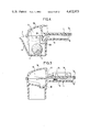
- FIG. 7 is a non cut-away view in the same perspective as FIG. 6;
- FIG. 8 is a partial cross-section view through the central part of the analysis apparatus.
- FIG. 9 is a partial perspective view of a second embodiment of the invention showing a pair of associated superposed cells
- FIG. 10 is a cross-section passing through cell radial feed pipes showing a pair of associated superposed cells
- FIG. 11 is a cross-section view along line XI--XI of FIG. 10;
- FIG. 12 is a cross-section view along line XII--XII of FIG. 9;
- FIG. 13 is a cross-section view of a pair of associated superposed cells along line XIII--XIII of FIG. 9;
- FIG. 14 is a partially cut-away elevation through the central portion of the apparatus.
- the figures show two analysis devices in accordance with the invention. Their main components are a rotor 1 having a plurality of peripheral reaction cells 2, each of which contains a reaction support 3.
- the rotor 1 is assembled from upper and lower generally disc-shaped members referenced IA and IB for the embodiment of FIGS. 1 to 8 and I A and I C for the embodiment of FIGS. 9 to 14.
- the reaction support is constituted by a single conventional reaction support comprising, for example, a bead of polystyrene covered with a compound having anti-body type properties.
- a plurality of small beads may be used, e.g. with a diameter of about of 10 to 20 microns.
- a barrier would be fitted in the cells suitable for retaining the beads therein while the apparatus is rotating, this barrier being embedded or glued in suitable notches.
- such a barrier would be of the molecular filter type.
- the solid reaction support could also be constituted by a suitable coating deposited on lower portions of the walls of the reaction cells 2.
- Reference 4 designates a central inlet orifice for a washing liquid which is let in as shown by an arrow D.
- Radial pipes 5 leave the central orifice and connect it to each peripheral cell 2.
- the pipes are disposed in a plane which is essentially perpendicular to the axis of rotation 6 of the apparatus. It should be observed that although the radial pipes 5 are defined in the embodiment shown by two complementary semi-cylindrical portions formed in the upper and lower disc-shaped I A and I B members (e.g. see FIGS. 3 and 10), other type of pipe could be envisaged such as, for example, a flat on one portion of the rotor and a groove on the other.
- Each reaction cell 2 has a peripheral liquid-removal orifice 7 (constituted by a gap between the outer edges of the upper and lower members I A and I B ).
- the liquid-removal orifice 7 is at the end of a spout 8 which is itself located at the rear of the reaction cell 2 when the rotor 1 is rotating in the washing direction, symbolised by an arrow A.
- Reference 9 designates a circular orifice arranged concentrially around the central inlet orifice 4.
- the liquid compound which contains the substance to be analysed is introduced into the circular orifice 9 in the direction shown by an arrow C.
- Each reaction cell 2 is coupled to a buffer cell 10 (FIGS. 1 to 8) or 10' (FIGS. 9 to 14) which shares a common wall 11 (FIGS. 1 to 8) or 11' (FIGS. 9 to 14) with the reaction cell 2 containing the reaction support 3.
- a passage is provided between cells 2 and 10 or 2 and 10' to allow liquid to pass around the wall 11 or 11'.
- the cells 2 and 10 are juxtaposed.
- the common wall 11 which separates them is a radial wall.
- the cells 2 and 10' are superposed, the common wall 11' being constituted by the upper surface of the reaction cell 2.
- the buffer cells 10 and 10' communicate with the concentric inlet orifice 9 via radial pipes 12.
- These radial pipes 12 are likewise defined by complementary portions formed on the members I A , I B of the rotor in FIGS. 1 to 8 or I A , I C of the rotor in FIGS. 9 to 14, but any other type of pipe could be envisaged.
- the upper surface of the rotor is equipped with means suitable for holding reagent-containing receptacles such as capsules, bulbs, etc. in such a position that, by centrifuging and opening these receptacles, the liquids they contain are introduced into the buffer cells 10 or 10'.
- reagent-containing receptacles such as capsules, bulbs, etc.
- the reagent-containing receptacles 13 and 14 are held on the upper surface of the rotor by locking clip supports such as 15.
- the upper parts of the associated pairs of cells 2 and 10 are closed by covers 16 each of which has an opening 17 facing the openings of the receptacles 13 and 14.
- the analysis apparatus is equipped with means, not illustrated, suitable for opening the receptacles 13 and 14 to be opened; these means may act e.g. by radiation, heating or crushing and are well known in the handling of pharmaceutical products.
- the reagent-containing receptacles are held in troughs 18.
- FIG. 13 illustrates a process for opening such a receptacle 19 whose outlet orifice 20 is situated at the end of an elongated portion 21. Before opening, the end of this elongated portion 21 is engaged in a suitable hole 22 in the radially outer end of the trough 18, in a position such that the receptacle has its radially inner end raised out of the trough 18.
- the cover 23 has a small lip 24 which overhangs the orifice 21 and ensures that all the liquid expelled from the receptacle 19 actually enters the buffer cell 10'.
- any other suitable means can be used to open the reagent-containing receptacles and to hold said receptacles on the upper surface of the rotor.
- the wall which is common to a buffer cell and to a reaction cell has a hole in it which puts the two cells in communication with each other.
- FIGS. 1 to 8 corresponds to the case where this common wall 11 is a radial wall.
- the hole is therefore located in the upper part thereof on its radially inner side and is in the form of a slot referenced 25.
- the inside profile of the buffer cells (10 or 10') is such that all the liquid brought into said cells by centrifuging in direction B is retained therein and cannot escape into the reaction cell 2 until centrifuging is stopped, where upon all the liquid thus brought into the buffer cell (10 or 10') passes into the reaction cell 2 via the orifice (25 or 26).
- the orifice 25 is disposed at a level higher than that reached by the liquid in the reaction cell 2 after the quantity retained in the buffer cell 10 has poured away.
- the buffer cell 10 has a retaining zone 27 near its outer surface. This retaining zone overhangs a removal ramp 28 which leads to the lower level of the orifice 25. Thus, after stopping centrifuging the liquid which was retained in the zone 27 pours into the reaction cell 2 via the ramp 28 and the orifice 25.
- the buffer cell 10' also has a retaining zone 29 positioned at its rear relative to the direction of rotation (B) used during buffer cell filling operations.
- baffle plate 30 is provided near the end of the feed pipe 5 which communicates with the cell 2.
- the rotor 1 is made to rotate by entirely conventional drive means.
- Reference 31 designates a rotary shaft which bears a protruding lug 32 engaging in a suitable notch 33 in the rotor.
- the apparatus operates as follows:
- a liquid such as serum or plasma which contains a substance to be analysed is inserted in the concentric orifice 9.
- centrifuging is carried out in the direction B.
- the liquid containing the substance to be analysed contained in the pipes 12 then moves into the buffer cells (10 or 10') and it is retained therein for as long as centrifuging continues.
- each reaction cell 2 has a sufficient volume to contain the bead and the liquid containing the substance to be analysed without the level thereof reaching the pipes 5.
- the excess liquid is expelled by centrifuging in the direction A while injecting a washing liquid, e.g. water, from the central opening 4 via the pipes 5.
- a washing liquid e.g. water
- This washing liquid thoroughly washes the reaction support and leaves the cell together with the excess liquid containing the substance to be analysed via the orifice 7 situated at the end of the spout 8.
- An optional drying step may then be performed by turning off the washing liquid inlet while continuing centrifuging.
- a first reagent--e.g. a polyglucoside--contained in one of the receptacles fixed in the upper wall of the rotor is then introduced.
- a direct analysis can be made e.g. by using a Geiger counter if the reagent contains radioactive isotopes or by injecting a second reagent such as a substrate which develops a coloured reaction by the same process to enable the enzymatic activity to be measured by means of a colorimeter or of a photometer.
- a second reagent such as a substrate which develops a coloured reaction by the same process to enable the enzymatic activity to be measured by means of a colorimeter or of a photometer.
- the inner and outer surfaces of the reaction cells 2 are parallel, at least in the neighborhood of a reading window referenced 40.
- reaction support is formed by a bead
- means such as 41 are provided in the analysis cell to prevent the bead from coming opposite the reading window.
- reaction supports disposed in the various reaction cells may correspond to different analysis which are made simultaneously on the same sample.
- the apparatus in accordance with the invention makes it possible to simply and rapidly obtain the five simultaneous dosages required for a thyroid analysis. Flexibility is also illustrated by the possibility among others of dividing the rotor into two zones to use some reaction cells as reference or check cells and of using different supports or identical reaction supports which would make it possible to carry out a single test for different customers.
- a compact apparatus can be produced in accordance with the invention.
- it may have a diameter of about 8 cm.
Landscapes
- Physics & Mathematics (AREA)
- Health & Medical Sciences (AREA)
- Life Sciences & Earth Sciences (AREA)
- Chemical & Material Sciences (AREA)
- Analytical Chemistry (AREA)
- Biochemistry (AREA)
- General Health & Medical Sciences (AREA)
- General Physics & Mathematics (AREA)
- Immunology (AREA)
- Pathology (AREA)
- Investigating Or Analysing Biological Materials (AREA)
- Automatic Analysis And Handling Materials Therefor (AREA)
Applications Claiming Priority (2)
| Application Number | Priority Date | Filing Date | Title |
|---|---|---|---|
| FR8026528 | 1980-12-15 | ||
| FR8026528A FR2496268A1 (fr) | 1980-12-15 | 1980-12-15 | Dispositif autonome d'analyse simultanee et procede de mise en oeuvre |
Publications (1)
| Publication Number | Publication Date |
|---|---|
| US4412973A true US4412973A (en) | 1983-11-01 |
Family
ID=9249067
Family Applications (1)
| Application Number | Title | Priority Date | Filing Date |
|---|---|---|---|
| US06/330,430 Expired - Fee Related US4412973A (en) | 1980-12-15 | 1981-12-14 | Autonomous simultaneous analysis apparatus and a method of using it |
Country Status (19)
| Country | Link |
|---|---|
| US (1) | US4412973A (ru) |
| EP (1) | EP0054262B1 (ru) |
| JP (1) | JPS57124254A (ru) |
| AR (1) | AR227344A1 (ru) |
| AT (1) | ATE10398T1 (ru) |
| AU (1) | AU542037B2 (ru) |
| BR (1) | BR8108113A (ru) |
| CA (1) | CA1168562A (ru) |
| DE (1) | DE3167343D1 (ru) |
| DK (1) | DK554081A (ru) |
| ES (1) | ES507948A0 (ru) |
| FR (1) | FR2496268A1 (ru) |
| IE (1) | IE52112B1 (ru) |
| IL (1) | IL64535A (ru) |
| IN (1) | IN157491B (ru) |
| NZ (1) | NZ199264A (ru) |
| RO (1) | RO83667B (ru) |
| SU (1) | SU1085502A3 (ru) |
| ZA (1) | ZA818668B (ru) |
Cited By (31)
| Publication number | Priority date | Publication date | Assignee | Title |
|---|---|---|---|---|
| US4643580A (en) * | 1983-12-08 | 1987-02-17 | Hoechst Aktiengesellschaft | Photometer head for small test volumes |
| US4743558A (en) * | 1984-10-26 | 1988-05-10 | Jean Guigan | Method of performing medical analysis on a sample of liquid by means of at least one liquid reagent, and apparatus for performing the method |
| US4817453A (en) * | 1985-12-06 | 1989-04-04 | E. I. Dupont De Nemours And Company | Fiber reinforced centrifuge rotor |
| US5122284A (en) * | 1990-06-04 | 1992-06-16 | Abaxis, Inc. | Apparatus and method for optically analyzing biological fluids |
| US5202418A (en) * | 1990-02-02 | 1993-04-13 | Ceskoslovenska Akademie Ved | Method of performing multiple synthesis of peptides on solid carrier |
| WO1993016391A1 (en) * | 1992-02-11 | 1993-08-19 | Abaxis, Inc. | Reagent container for analytical rotor |
| US5242803A (en) * | 1987-07-17 | 1993-09-07 | Martin Marietta Energy Systems, Inc. | Rotor assembly and assay method |
| US5358691A (en) * | 1992-03-27 | 1994-10-25 | Abbott Laboratories | Automated continuous and random access analytical system |
| US5507410A (en) * | 1992-03-27 | 1996-04-16 | Abbott Laboratories | Meia cartridge feeder |
| US5536471A (en) * | 1992-03-27 | 1996-07-16 | Abbott Laboratories | Syringe with bubble flushing |
| US5540890A (en) * | 1992-03-27 | 1996-07-30 | Abbott Laboratories | Capped-closure for a container |
| US5575978A (en) * | 1992-03-27 | 1996-11-19 | Abbott Laboratories | Sample container segment assembly |
| US5578494A (en) * | 1992-03-27 | 1996-11-26 | Abbott Laboratories | Cap actuator for opening and closing a container |
| US5605665A (en) * | 1992-03-27 | 1997-02-25 | Abbott Laboratories | Reaction vessel |
| US5610069A (en) * | 1992-03-27 | 1997-03-11 | Abbott Laboratories | Apparatus and method for washing clinical apparatus |
| US5627522A (en) * | 1992-03-27 | 1997-05-06 | Abbott Laboratories | Automated liquid level sensing system |
| US5635364A (en) * | 1992-03-27 | 1997-06-03 | Abbott Laboratories | Assay verification control for an automated analytical system |
| US5646049A (en) * | 1992-03-27 | 1997-07-08 | Abbott Laboratories | Scheduling operation of an automated analytical system |
| WO1999025470A1 (en) * | 1997-11-19 | 1999-05-27 | Trega Biosciences, Inc. | Apparatus and method for separation of liquid and solid phases for solid phase organic syntheses |
| US5914273A (en) * | 1989-12-13 | 1999-06-22 | Genelabs Diagnostics Pte Ltd | Analytical apparatus and method for automated blot assay |
| US5960160A (en) * | 1992-03-27 | 1999-09-28 | Abbott Laboratories | Liquid heater assembly with a pair temperature controlled electric heating elements and a coiled tube therebetween |
| US6190617B1 (en) | 1992-03-27 | 2001-02-20 | Abbott Laboratories | Sample container segment assembly |
| US6348176B1 (en) | 1999-02-11 | 2002-02-19 | Careside, Inc. | Cartridge-based analytical instrument using centrifugal force/pressure for metering/transport of fluids |
| US20020028159A1 (en) * | 1999-12-13 | 2002-03-07 | Michal Lebl | Oligonucleotide synthesizer |
| US20020044894A1 (en) * | 1999-12-13 | 2002-04-18 | Michal Lebl | Oligonucleotide synthesizer |
| US6391264B2 (en) | 1999-02-11 | 2002-05-21 | Careside, Inc. | Cartridge-based analytical instrument with rotor balance and cartridge lock/eject system |
| US6531095B2 (en) | 1999-02-11 | 2003-03-11 | Careside, Inc. | Cartridge-based analytical instrument with optical detector |
| US20040208797A1 (en) * | 1999-01-29 | 2004-10-21 | Michal Lebl | Apparatus and method for separation of liquid phases of different density and for fluorous phase organic syntheses |
| US20070110638A1 (en) * | 2005-09-14 | 2007-05-17 | Heiner David L | Continuous polymer synthesizer |
| DE102014019526A1 (de) * | 2014-12-23 | 2016-06-23 | Testo Ag | Untersuchungsverfahren, scheibenförmiger Probenträger und Verwendung eines Probenträgers |
| US20160354774A1 (en) * | 2015-06-07 | 2016-12-08 | Delta Electronics, Inc. | Centrifugal flow channel device and centrifugal flow channel body |
Families Citing this family (4)
| Publication number | Priority date | Publication date | Assignee | Title |
|---|---|---|---|---|
| EP0217000B1 (en) * | 1985-07-15 | 1991-01-23 | Abbott Laboratories | Reagent containment system for a clinical analyser |
| US4740472A (en) * | 1985-08-05 | 1988-04-26 | The United States Of America As Represented By The United States Department Of Energy | Method and apparatus for automated processing and aliquoting of whole blood samples for analysis in a centrifugal fast analyzer |
| US4835106A (en) * | 1987-07-17 | 1989-05-30 | Martin Marietta Energy Systems, Inc. | Rotor for processing liquids using movable capillary tubes |
| FR2806165B1 (fr) * | 2000-03-09 | 2003-01-17 | Genomic Sa | Automate pour l'analyse biologique |
Citations (6)
| Publication number | Priority date | Publication date | Assignee | Title |
|---|---|---|---|---|
| AU468478B2 (en) * | 1959-11-20 | 1976-01-15 | Biodynamics, Inc | Centrifuge clinical chemistry analysis system |
| US4244694A (en) * | 1978-03-31 | 1981-01-13 | Union Carbide Corporation | Reactor/separator device for use in automated solid phase immunoassay |
| US4244916A (en) * | 1977-08-18 | 1981-01-13 | Jean Guigan | Device for conditioning a sample of liquid for analyzing with internal filter |
| US4279862A (en) * | 1977-11-17 | 1981-07-21 | Bretaudiere Jean Pierre | Centrifugal photometric analyzer |
| US4284602A (en) * | 1979-12-10 | 1981-08-18 | Immutron, Inc. | Integrated fluid manipulator |
| US4314968A (en) * | 1979-10-26 | 1982-02-09 | Jean Guigan | Simultaneous analysis apparatus |
Family Cites Families (3)
| Publication number | Priority date | Publication date | Assignee | Title |
|---|---|---|---|---|
| US3864089A (en) * | 1973-12-10 | 1975-02-04 | Atomic Energy Commission | Multiple-sample rotor assembly for blood fraction preparation |
| US4135883A (en) * | 1977-08-29 | 1979-01-23 | Bio-Dynamics Inc. | Blood analyzer system |
| FR2468909A1 (fr) * | 1979-10-26 | 1981-05-08 | Guigan Jean | Dispositif d'analyse simultanee |
-
1980
- 1980-12-15 FR FR8026528A patent/FR2496268A1/fr active Granted
-
1981
- 1981-12-03 IN IN764/DEL/81A patent/IN157491B/en unknown
- 1981-12-09 SU SU813361533A patent/SU1085502A3/ru active
- 1981-12-10 AT AT81110311T patent/ATE10398T1/de not_active IP Right Cessation
- 1981-12-10 EP EP81110311A patent/EP0054262B1/fr not_active Expired
- 1981-12-10 DE DE8181110311T patent/DE3167343D1/de not_active Expired
- 1981-12-11 RO RO105976A patent/RO83667B/ro unknown
- 1981-12-14 IL IL64535A patent/IL64535A/xx unknown
- 1981-12-14 BR BR8108113A patent/BR8108113A/pt unknown
- 1981-12-14 ES ES507948A patent/ES507948A0/es active Granted
- 1981-12-14 NZ NZ199264A patent/NZ199264A/en unknown
- 1981-12-14 JP JP56201447A patent/JPS57124254A/ja active Pending
- 1981-12-14 US US06/330,430 patent/US4412973A/en not_active Expired - Fee Related
- 1981-12-14 AR AR287801A patent/AR227344A1/es active
- 1981-12-14 ZA ZA818668A patent/ZA818668B/xx unknown
- 1981-12-14 AU AU78496/81A patent/AU542037B2/en not_active Ceased
- 1981-12-14 IE IE2927/81A patent/IE52112B1/en unknown
- 1981-12-14 DK DK554081A patent/DK554081A/da not_active Application Discontinuation
- 1981-12-14 CA CA000392207A patent/CA1168562A/fr not_active Expired
Patent Citations (6)
| Publication number | Priority date | Publication date | Assignee | Title |
|---|---|---|---|---|
| AU468478B2 (en) * | 1959-11-20 | 1976-01-15 | Biodynamics, Inc | Centrifuge clinical chemistry analysis system |
| US4244916A (en) * | 1977-08-18 | 1981-01-13 | Jean Guigan | Device for conditioning a sample of liquid for analyzing with internal filter |
| US4279862A (en) * | 1977-11-17 | 1981-07-21 | Bretaudiere Jean Pierre | Centrifugal photometric analyzer |
| US4244694A (en) * | 1978-03-31 | 1981-01-13 | Union Carbide Corporation | Reactor/separator device for use in automated solid phase immunoassay |
| US4314968A (en) * | 1979-10-26 | 1982-02-09 | Jean Guigan | Simultaneous analysis apparatus |
| US4284602A (en) * | 1979-12-10 | 1981-08-18 | Immutron, Inc. | Integrated fluid manipulator |
Cited By (54)
| Publication number | Priority date | Publication date | Assignee | Title |
|---|---|---|---|---|
| US4643580A (en) * | 1983-12-08 | 1987-02-17 | Hoechst Aktiengesellschaft | Photometer head for small test volumes |
| US4743558A (en) * | 1984-10-26 | 1988-05-10 | Jean Guigan | Method of performing medical analysis on a sample of liquid by means of at least one liquid reagent, and apparatus for performing the method |
| US4817453A (en) * | 1985-12-06 | 1989-04-04 | E. I. Dupont De Nemours And Company | Fiber reinforced centrifuge rotor |
| US5242803A (en) * | 1987-07-17 | 1993-09-07 | Martin Marietta Energy Systems, Inc. | Rotor assembly and assay method |
| US5914273A (en) * | 1989-12-13 | 1999-06-22 | Genelabs Diagnostics Pte Ltd | Analytical apparatus and method for automated blot assay |
| US5202418A (en) * | 1990-02-02 | 1993-04-13 | Ceskoslovenska Akademie Ved | Method of performing multiple synthesis of peptides on solid carrier |
| US5338831A (en) * | 1990-02-02 | 1994-08-16 | Academy Of Sciences Of The Czech Republic Changed From Ceskoslovenska Akademie Ved | Method of making multiple synthesis of peptides on solid support |
| US5342585A (en) * | 1990-02-02 | 1994-08-30 | Academy Of Sciences Of The Czech Republic | Apparatus for making multiple synthesis of peptides on solid support |
| US5122284A (en) * | 1990-06-04 | 1992-06-16 | Abaxis, Inc. | Apparatus and method for optically analyzing biological fluids |
| WO1993016391A1 (en) * | 1992-02-11 | 1993-08-19 | Abaxis, Inc. | Reagent container for analytical rotor |
| US5304348A (en) * | 1992-02-11 | 1994-04-19 | Abaxis, Inc. | Reagent container for analytical rotor |
| US6096561A (en) * | 1992-03-27 | 2000-08-01 | Abbott Laboratories | Scheduling operation of an automated analytical system |
| US5762878A (en) * | 1992-03-27 | 1998-06-09 | Abbott Laboratories | Sample container segment assembly |
| US5482861A (en) * | 1992-03-27 | 1996-01-09 | Abbott Laboratories | Automated continuous and random access analytical system |
| US5507410A (en) * | 1992-03-27 | 1996-04-16 | Abbott Laboratories | Meia cartridge feeder |
| US5536471A (en) * | 1992-03-27 | 1996-07-16 | Abbott Laboratories | Syringe with bubble flushing |
| US5540890A (en) * | 1992-03-27 | 1996-07-30 | Abbott Laboratories | Capped-closure for a container |
| US5575978A (en) * | 1992-03-27 | 1996-11-19 | Abbott Laboratories | Sample container segment assembly |
| US5578494A (en) * | 1992-03-27 | 1996-11-26 | Abbott Laboratories | Cap actuator for opening and closing a container |
| US5605665A (en) * | 1992-03-27 | 1997-02-25 | Abbott Laboratories | Reaction vessel |
| US5610069A (en) * | 1992-03-27 | 1997-03-11 | Abbott Laboratories | Apparatus and method for washing clinical apparatus |
| US5627522A (en) * | 1992-03-27 | 1997-05-06 | Abbott Laboratories | Automated liquid level sensing system |
| US5635364A (en) * | 1992-03-27 | 1997-06-03 | Abbott Laboratories | Assay verification control for an automated analytical system |
| US5646049A (en) * | 1992-03-27 | 1997-07-08 | Abbott Laboratories | Scheduling operation of an automated analytical system |
| US5451528A (en) * | 1992-03-27 | 1995-09-19 | Abbott Laboratories | Methods for providing homogeneous reagents |
| US5960160A (en) * | 1992-03-27 | 1999-09-28 | Abbott Laboratories | Liquid heater assembly with a pair temperature controlled electric heating elements and a coiled tube therebetween |
| US5358691A (en) * | 1992-03-27 | 1994-10-25 | Abbott Laboratories | Automated continuous and random access analytical system |
| US6190617B1 (en) | 1992-03-27 | 2001-02-20 | Abbott Laboratories | Sample container segment assembly |
| US6121054A (en) * | 1997-11-19 | 2000-09-19 | Trega Biosciences, Inc. | Method for separation of liquid and solid phases for solid phase organic syntheses |
| WO1999025470A1 (en) * | 1997-11-19 | 1999-05-27 | Trega Biosciences, Inc. | Apparatus and method for separation of liquid and solid phases for solid phase organic syntheses |
| AU751424B2 (en) * | 1997-11-19 | 2002-08-15 | Trega Biosciences, Inc. | Apparatus and method for separation of liquid and solid phases for solid phase organic syntheses |
| US8394923B2 (en) | 1999-01-29 | 2013-03-12 | Illumina, Inc. | Apparatus and method for separation of liquid phases of different density and for fluorous phase organic syntheses |
| US7977456B2 (en) * | 1999-01-29 | 2011-07-12 | Illumina, Inc. | Apparatus and method for separation of liquid phases of different density and for fluorous phase organic syntheses |
| US8178652B2 (en) | 1999-01-29 | 2012-05-15 | Illumina, Inc. | Apparatus and method for separation of liquid phases of different density and for fluorous phase organic syntheses |
| US20040208797A1 (en) * | 1999-01-29 | 2004-10-21 | Michal Lebl | Apparatus and method for separation of liquid phases of different density and for fluorous phase organic syntheses |
| US6846460B1 (en) * | 1999-01-29 | 2005-01-25 | Illumina, Inc. | Apparatus and method for separation of liquid phases of different density and for fluorous phase organic syntheses |
| US6348176B1 (en) | 1999-02-11 | 2002-02-19 | Careside, Inc. | Cartridge-based analytical instrument using centrifugal force/pressure for metering/transport of fluids |
| US6391264B2 (en) | 1999-02-11 | 2002-05-21 | Careside, Inc. | Cartridge-based analytical instrument with rotor balance and cartridge lock/eject system |
| US6531095B2 (en) | 1999-02-11 | 2003-03-11 | Careside, Inc. | Cartridge-based analytical instrument with optical detector |
| US20020044894A1 (en) * | 1999-12-13 | 2002-04-18 | Michal Lebl | Oligonucleotide synthesizer |
| US6663832B2 (en) * | 1999-12-13 | 2003-12-16 | Illumina, Inc. | Oligonucleotide synthesizer |
| US7390459B2 (en) | 1999-12-13 | 2008-06-24 | Illumina, Inc. | Oligonucleotide synthesizer |
| US20090023605A1 (en) * | 1999-12-13 | 2009-01-22 | Michal Lebl | Oligonucleotide synthesizer |
| US8465694B2 (en) | 1999-12-13 | 2013-06-18 | Illumina, Inc. | Oligonucleotide synthesizer |
| US20020028159A1 (en) * | 1999-12-13 | 2002-03-07 | Michal Lebl | Oligonucleotide synthesizer |
| US20110143965A1 (en) * | 1999-12-13 | 2011-06-16 | Michal Lebl | Oligonucleotide synthesizer |
| US7914739B2 (en) | 2005-09-14 | 2011-03-29 | Illumina, Inc. | Continuous polymer synthesizer |
| US20070110638A1 (en) * | 2005-09-14 | 2007-05-17 | Heiner David L | Continuous polymer synthesizer |
| US20110136696A1 (en) * | 2005-09-14 | 2011-06-09 | Illumina, Inc. | Continuous polymer synthesizer |
| US20070117178A1 (en) * | 2005-09-14 | 2007-05-24 | Heiner David L | Continuous polymer synthesizer |
| US8731721B2 (en) | 2005-09-14 | 2014-05-20 | Illumina, Inc. | Continuous polymer synthesizer |
| DE102014019526A1 (de) * | 2014-12-23 | 2016-06-23 | Testo Ag | Untersuchungsverfahren, scheibenförmiger Probenträger und Verwendung eines Probenträgers |
| DE102014019526B4 (de) * | 2014-12-23 | 2016-10-27 | Testo Ag | Untersuchungsverfahren, scheibenförmiger Probenträger und Verwendung eines Probenträgers |
| US20160354774A1 (en) * | 2015-06-07 | 2016-12-08 | Delta Electronics, Inc. | Centrifugal flow channel device and centrifugal flow channel body |
Also Published As
| Publication number | Publication date |
|---|---|
| BR8108113A (pt) | 1982-09-21 |
| ZA818668B (en) | 1982-10-27 |
| IL64535A0 (en) | 1982-03-31 |
| CA1168562A (fr) | 1984-06-05 |
| FR2496268B1 (ru) | 1982-12-17 |
| AU7849681A (en) | 1982-06-24 |
| JPS57124254A (en) | 1982-08-03 |
| RO83667B (ro) | 1984-06-30 |
| SU1085502A3 (ru) | 1984-04-07 |
| ATE10398T1 (de) | 1984-12-15 |
| IE52112B1 (en) | 1987-06-24 |
| IL64535A (en) | 1987-10-30 |
| ES8301366A1 (es) | 1982-11-16 |
| IN157491B (ru) | 1986-04-12 |
| EP0054262A1 (fr) | 1982-06-23 |
| EP0054262B1 (fr) | 1984-11-21 |
| AU542037B2 (en) | 1985-01-31 |
| DK554081A (da) | 1982-06-16 |
| DE3167343D1 (en) | 1985-01-03 |
| AR227344A1 (es) | 1982-10-15 |
| ES507948A0 (es) | 1982-11-16 |
| NZ199264A (en) | 1984-03-16 |
| RO83667A (ro) | 1984-05-12 |
| FR2496268A1 (fr) | 1982-06-18 |
| IE812927L (en) | 1982-06-15 |
Similar Documents
| Publication | Publication Date | Title |
|---|---|---|
| US4412973A (en) | Autonomous simultaneous analysis apparatus and a method of using it | |
| IE50394B1 (en) | Simultaneous analysis apparatus | |
| KR880001690B1 (ko) | 원심분리기용 처리장치 카아드 | |
| US3899296A (en) | Whole blood analysis rotor for a multistation dynamic photometer | |
| US3901658A (en) | Whole blood analysis rotor assembly having removable cellular sedimentation bowl | |
| US3497320A (en) | Automated chemical analyzer | |
| AU745712B2 (en) | Reagent package | |
| US4648529A (en) | Dispensing apparatus for storing, draining and dispensing beads | |
| US4390499A (en) | Chemical analysis system including a test package and rotor combination | |
| CA1300006C (en) | Self-contained immunoassay element | |
| KR880001335B1 (ko) | 반응 트레이 | |
| US4431606A (en) | Multicuvette rotor for analyzer | |
| US4639242A (en) | Vessel and procedure for automated assay | |
| US3990852A (en) | Immunological analysis apparatus | |
| JPS59501963A (ja) | 一体化シングルチュ−ブ・プランジャによる免疫検定システム | |
| US4463097A (en) | Method and device for bringing a liquid sample successively into contact with a number of reagents | |
| JPH07500910A (ja) | 分析ロータの試料計量口 | |
| NZ201901A (en) | An apparatus suitable for performing automated heterogeneous immunoassays in a plurality of samples | |
| IL45316A (en) | Simplified rotor for fast analyzer of rotary cuvette type | |
| JPS60238761A (ja) | 化学的試験のための装置 | |
| JPS61264263A (ja) | 免疫反応を用いる生物学的分析方法及び装置 | |
| USRE30562E (en) | Immunological testing devices | |
| US4663296A (en) | Multicuvette rotor for analyzer | |
| US4470954A (en) | Rotor or carrier for centrifugal analyzer and bead washer | |
| JPH0623767B2 (ja) | 液体試料の分析方法およびその装置 |
Legal Events
| Date | Code | Title | Description |
|---|---|---|---|
| MAFP | Maintenance fee payment |
Free format text: PAYMENT OF MAINTENANCE FEE, 4TH YEAR, PL 96-517 (ORIGINAL EVENT CODE: M170); ENTITY STATUS OF PATENT OWNER: SMALL ENTITY Year of fee payment: 4 |
|
| FEPP | Fee payment procedure |
Free format text: PAYOR NUMBER ASSIGNED (ORIGINAL EVENT CODE: ASPN); ENTITY STATUS OF PATENT OWNER: SMALL ENTITY |
|
| FEPP | Fee payment procedure |
Free format text: MAINTENANCE FEE REMINDER MAILED (ORIGINAL EVENT CODE: REM.); ENTITY STATUS OF PATENT OWNER: SMALL ENTITY |
|
| LAPS | Lapse for failure to pay maintenance fees | ||
| FP | Lapsed due to failure to pay maintenance fee |
Effective date: 19911103 |
|
| STCH | Information on status: patent discontinuation |
Free format text: PATENT EXPIRED DUE TO NONPAYMENT OF MAINTENANCE FEES UNDER 37 CFR 1.362 |