US4403563A - Electric sewing machine driving apparatus - Google Patents
Electric sewing machine driving apparatus Download PDFInfo
- Publication number
- US4403563A US4403563A US06/287,075 US28707581A US4403563A US 4403563 A US4403563 A US 4403563A US 28707581 A US28707581 A US 28707581A US 4403563 A US4403563 A US 4403563A
- Authority
- US
- United States
- Prior art keywords
- voltage
- sewing machine
- capacitor
- coil
- brake
- Prior art date
- Legal status (The legal status is an assumption and is not a legal conclusion. Google has not performed a legal analysis and makes no representation as to the accuracy of the status listed.)
- Expired - Lifetime
Links
Images


Classifications
-
- D—TEXTILES; PAPER
- D05—SEWING; EMBROIDERING; TUFTING
- D05B—SEWING
- D05B69/00—Driving-gear; Control devices
- D05B69/22—Devices for stopping drive when sewing tools have reached a predetermined position
- D05B69/26—Devices for stopping drive when sewing tools have reached a predetermined position with automatic means to reduce speed of drive, e.g. in one or more steps
-
- H—ELECTRICITY
- H02—GENERATION; CONVERSION OR DISTRIBUTION OF ELECTRIC POWER
- H02P—CONTROL OR REGULATION OF ELECTRIC MOTORS, ELECTRIC GENERATORS OR DYNAMO-ELECTRIC CONVERTERS; CONTROLLING TRANSFORMERS, REACTORS OR CHOKE COILS
- H02P3/00—Arrangements for stopping or slowing electric motors, generators, or dynamo-electric converters
- H02P3/02—Details of stopping control
- H02P3/04—Means for stopping or slowing by a separate brake, e.g. friction brake or eddy-current brake
Definitions
- the present invention relates to an industrial electric sewing machine driving apparatus including an electromagnetic clutch mechanism for transmitting the torque of a motor to a sewing machine to drive it and an electromagnetic brake mechanism for applying a braking force to the sewing machine.
- Conventional electromagnetic clutch and brake mechanisms of the above type have the structure such that a clutch ring and a brake ring, each thereof comprising a friction member made of cork, etc., are arranged movably in the axial direction so that the torque of a continuously operating motor is transmitted to an output shaft or the output shaft is braked through the friction member actuated by an electromagnetic force.
- the mechanism includes a pair of coils, namely, a clutch coil and a brake coil, so that the output shaft is accelerated when the clutch coil is energized and the output shaft is decelerated when the brake coil is energized.
- the clutch and brake mechanisms comprise the axially movable clutch and brake rings as mentioned above, the delays in the operations of the clutch and brake coils give rise to fatal deficiencies including the unstable speed control and the deterioration of accuracy of the predetermined needle position stopping operation, etc. More particularly, a delay in the rise of an electric current flowing through the brake coil when it is energized causes, in turn, a delay of a braking force to be applied, which increases the deviation of the actual stopping position from the position of the generation of a stop signal associated, thus presenting a dominant cause of the deterioration of accuracy of the predetermined needle position stopping operation.
- an improved electric sewing machine driving apparatus so designed that an electric power discharged from a capacitor, which has been charged beforehand to a high voltage, is applied to a brake coil to decrease the deviation of the actual stopping position from the position of the stop signal generation, thereby raising accuracy of the predetermined needle position stopping operation.
- FIG. 1 is a diagram showing general operational characteristics of an industrial electric sewing machine
- FIG. 2 is a diagram showing operational characteristics of a conventional industrial electric sewing machine in an operational range from its thread trimming operation to its stop;
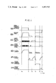
- FIG. 3 is a diagram showing operational characteristics of an apparatus according to this invention which corresponds to FIG. 2;
- FIG. 4 is a circuit diagram of an electric sewing machine driving apparatus according to an embodiment of this invention.
- FIG. 1 showing a general operational pattern in the control of an industrial electric sewing machine
- a pedal of the machine is forwardly depressed at a time t 0
- a clutch current flows and the machine speed is increased.
- the pedal is restored to its neutral position at a time t 1
- the clutch current decreases and a brake current flows.
- the sewing machine is decelerated rapidly and the clutch current is switched on and off to cause the machine to operate stably at a low speed.
- a lower needle position signal is generated at a time t 2 so that the clutch current is decreased and the brake current flows again, and the machine stops at a lower needle position.
- FIG. 2 shows in greater detail the time interval from t 3 to t 4 in FIG. 1 with respect to the machine speed, clutch current and brake current, and the deficiencies of the operation of a conventional machine will now be described with reference to FIG. 2.
- the clutch When the pedal is depressed backwardly at a time a (corresponding to the time t 3 in FIG. 1), the clutch is energized immediately, so that a current starts to flow through the clutch coil and increases in proportion to the inductance of the clutch coil. Due to a delay in the rise of the clutch current and the corresponding delay in the movement of the clutch ring, the machine starts rotating only at a time b.
- the machine is feedback controlled to rotate at a speed b 0 , but actually the machine speed settles at the speed b 0 after it has experienced an overshoot and an undershoot during the rising period of the speed.
- the clutch current is turned on and off with a suitable duty cycle in accordance with the detected speed.
- the application of a load for its thread trimming operation is started at a time e and the machine speed starts decreasing.
- the clutch current increases correspondingly and the machine speed drops to a speed b 2 .
- the thread trimming load terminates, the machine speed is restored and is stabilized at the speed b 0 .
- An upper needle position signal is generated at a time f (corresponding to the time t 4 in FIG. 1) so that the clutch is de-energized and the brake is energized.
- the brake current increases in proportion to the inductance of the brake coil.
- the brake ring is attracted so that the application of the braking force starts at a time g.
- the machine speed decreases along a descending slope corresponding to the inertia of the mechanical system and the braking force, and the machine stops at a time h.
- the angle of rotation of the machine from the time of generation of the upper needle position signal to the time of the stoppage of rotation of the machine is about 15 degrees. This angle of rotation from the signal generation to the stoppage of the machine rotation varies in dependence upon various factors as mentioned below, and the variation determines the needle positioning accuracy.
- the machine is feedback controlled to maintain its speed at b 0 .
- a deviation of the machine speed from the speed b 0 such as a speed drop caused by the application of a thread trimming load immediately before the application of a stop signal, an over-shoot caused by the reaction of the speed drop, and the like.
- the magnitude of the thread trimming load varies depending on the thickness of the thread and the manner in which the thread is trimmed, so that the machine speed varies correspondingly.
- the rate of rise of the brake current increases with an increase of the power supply voltage, which naturally reduces the time intervals T 0 and T 1 .
- the brake coil current and the friction coefficient of the friction member decrease as the temperature of the brake mechanism rises, with the result that the braking force decreases and the time intervals T 0 and T 1 increase.
- the needle positioning accuracy varies in dependence on the above-mentioned various factors, and the deviation of the angle of rotation of the machine with respect to the desired needle stopping position is generally on the order of ⁇ 5 degrees. This deviation presents a main cause of machine malfunctions such as the slipping-off of a thread, the breakage of a needle or the like.
- numeral 1 designates an AC power source, 2 a power transformer, 3 a clutch coil (an inductor), 4 a brake coil, 5 a thread trimming solenoid, 6 a thread wiping solenoid, 7 a choke coil, 8 a constant voltage IC, 9 a microcomputer, 10 an OP AMP (operational amplifier), 11 a comparator, 12 a lower needle position signal generator, 13 an upper needle position signal generator, D 1 to D 15 diodes, Q 1 to Q 8 transistors, C 1 to C 5 capacitors, and R 1 to R 13 resistors.
- An upper power supply line serves as a load driving power source having a large current capacity and an unstabilized power supply voltage of DC 24 V is generated between the terminals of the capacitor C 1 .
- a lower power supply line serves as a control power source having a small current capacity and a stabilized power supply voltage of DC 5 V is generated between the terminals of the capacitor C 4 . Both power sources are connected respectively to a common ground potential line.
- the microcomputer 9 is supplied with a lower needle position signal from the lower needle position signal generator 12, an upper needle position signal from the upper needle position signal generator 13, and other signals such as a pedal position signal and a speed signal, which are not shown, and generates signals for driving the respective load transistors. Under the control of the output signal from the microcomputer 9, the transistor Q 1 is turned on and off to cause an interrupted current to flow through the clutch coil 3 as shown in (E) of FIG. 1.
- the resistor R 1 and the diode D 5 from a flywheel circuit which regulates a decrease in the interrupted current.
- the thread trimming solenoid 5 and the thread wiping solenoid 6 are controlled respectively as shown in (G) and (H) of FIG. 1 under the control of the output signals from the microcomputer 9.
- the combinations of the resistor R 3 and the diode D 9 ; and the resistor R 4 and the diode D 10 form respective flywheel circuits.
- the transistor Q 8 connected to the output of the OP AMP 10 and the transistor Q 5 connected to the output circuit of the transistor Q 8 are respectively turned on and off with this repetition frequency.
- the transistor Q 5 , the choke coil 7, the diode D 11 and the capacitor C 2 form a booster type chopper circuit.
- the electromagnetic energy stored in the choke coil 7 while the transistor Q 5 is conducting discharges through the diode D 11 to charge the capacitor C 2 upon the turning-off of the transistor Q 5 .
- the comparator 11 operates as a voltage comparator.
- the voltage across the capacitor C 2 is divided by the resistors R 6 and R 7 and the divided voltage is applied to the comparator 11.
- the output of the comparator 11 supplies a clamping voltage between the terminals of the capacitor C 5 , so that the oscillation of the OP AMP 10 stops and the transistor Q 5 is held nonconductive.
- the capacitor C 2 stays in a charged state with the voltage thereacross remaining at the level of the predetermined voltage.
- the capacitance and the charged voltage of the capacitor C 2 are important factors. It is necessary that the discharged energy of 1/2 ⁇ C 2 (V 2 c2 -V 2 c1 ) takes a sufficient value for driving the brake coil 4.
- the comparator 11 operates to control the charged voltage of the capacitor C 2 at a constant level in spite of variations in the power supply voltage, variations in the power supply voltage do not cause any change of the braking force and consequently any deviation of the stopping position.
- the operation of the thread wiping solenoid 6 is usually of the pattern shown at (H) of FIG. 1.
- the solenoid 6 is turned on during several tens milliseconds from the time of generation of the final upper needle position signal.
- the turning-on of the transistor Q 7 to discharge the capacitor C 2 in synchronism with the generation of the upper needle position signal is useful in simplifying the circuit construction.
- the booster type chopper circuit is used to charge the capacitor C 2 to a high voltage
- the present invention is not limited to this means.
- these known means fall within the scope of the present invention.
- the charged voltage of the capacitor C 2 is selected to be high and controlled at a constant value
- the present invention is not limited to the construction which controls the charged voltage of the capacitor C 2 at a constant value. It is because that, even if the charged voltage of the capacitor C 2 is not controlled at a constant value but it is increased to take a sufficiently high value, it is possible yet to obtain a satisfactory effect in reducing the so-called slipping angle before the actual stoppage of the machine thereby to improve the needle positioning accuracy, and besides it does not depart in any way from the scope of this invention.
- the present invention provides an electric sewing machine driving apparatus in which the charge of a capacitor, which has been charged beforehand to have a high voltage thereacross, is discharged through a brake coil to reduce the so-called slipping angle between the position of the generation of a stop signal and that of the actual stoppage of the sewing machine and thereby to improve the needle positioning accuracy of the sewing machine, and that the present invention brings a great advantage to assure satisfactory needle positioning accuracy of the sewing machine in spite of various external varying conditions such as variations in the thread trimming load, power supply voltage and ambient temperature, thereby preventing the occurrence of machine troubles such as the slipping-off of a thread and the breakage of a needle even when the apparatus of this invention is applied to any type of sewing machines.
Landscapes
- Engineering & Computer Science (AREA)
- Mechanical Engineering (AREA)
- Textile Engineering (AREA)
- Power Engineering (AREA)
- Sewing Machines And Sewing (AREA)
- Control Of Position Or Direction (AREA)
- Stopping Of Electric Motors (AREA)
Applications Claiming Priority (2)
| Application Number | Priority Date | Filing Date | Title |
|---|---|---|---|
| JP10609980A JPS5731008A (en) | 1980-07-31 | 1980-07-31 | Sewing machine driving device |
| JP55-106099 | 1980-07-31 |
Publications (1)
| Publication Number | Publication Date |
|---|---|
| US4403563A true US4403563A (en) | 1983-09-13 |
Family
ID=14425070
Family Applications (1)
| Application Number | Title | Priority Date | Filing Date |
|---|---|---|---|
| US06/287,075 Expired - Lifetime US4403563A (en) | 1980-07-31 | 1981-07-21 | Electric sewing machine driving apparatus |
Country Status (6)
| Country | Link |
|---|---|
| US (1) | US4403563A (OSRAM) |
| EP (1) | EP0045484B1 (OSRAM) |
| JP (1) | JPS5731008A (OSRAM) |
| KR (1) | KR840002417B1 (OSRAM) |
| CA (1) | CA1179419A (OSRAM) |
| DE (1) | DE3169042D1 (OSRAM) |
Cited By (3)
| Publication number | Priority date | Publication date | Assignee | Title |
|---|---|---|---|---|
| US4530297A (en) * | 1983-01-25 | 1985-07-23 | Mitsubishi Denki Kabushiki Kaisha | Speed control apparatus for sewing machine |
| US4732099A (en) * | 1985-11-06 | 1988-03-22 | Matsushita Electric Industrial Co., Ltd. | Motor controller for a sewing machine |
| US5157307A (en) * | 1988-06-23 | 1992-10-20 | Matsushita Electric Industrial Co., Ltd. | Sewing machine drive apparatus |
Families Citing this family (3)
| Publication number | Priority date | Publication date | Assignee | Title |
|---|---|---|---|---|
| DE3802784C1 (OSRAM) * | 1988-01-30 | 1989-08-17 | Pfaff Haushaltmaschinen Gmbh, 7500 Karlsruhe, De | |
| JP2876818B2 (ja) * | 1991-05-20 | 1999-03-31 | ブラザー工業株式会社 | 自動糸切り装置付きミシン |
| KR100488522B1 (ko) | 2003-02-07 | 2005-05-11 | 삼성전자주식회사 | 모터제어장치 |
Citations (3)
| Publication number | Priority date | Publication date | Assignee | Title |
|---|---|---|---|---|
| US4161921A (en) * | 1976-07-23 | 1979-07-24 | Aisin Seiki Co., Ltd. | Motor control system for sewing machine |
| US4195582A (en) * | 1978-09-14 | 1980-04-01 | Teledyne Mid-America Corporation | Sewing machine stitching control system |
| US4351254A (en) * | 1981-06-08 | 1982-09-28 | The Singer Company | Sewing machine needle positioning |
Family Cites Families (5)
| Publication number | Priority date | Publication date | Assignee | Title |
|---|---|---|---|---|
| DE1177732B (de) * | 1961-10-14 | 1964-09-10 | Elektromotoren Und Elek Sche A | Elektrische Antriebseinrichtung, insbesondere fuer Naehmaschinen, mit Mitteln zum genauen Anhalten des Antriebs in vorausbestimmter Stellung |
| US3263099A (en) * | 1962-05-25 | 1966-07-26 | Gen Electric | Power amplifier circuit |
| FR1335709A (fr) * | 1962-08-08 | 1963-08-23 | Frankl & Kirchner | Dispositif électrique d'entraînement notamment pour machines à coudre, comprenant des moyens pour arrêter le mécanisme d'entraînement dans une position déterminée à l'avance |
| US3810438A (en) * | 1970-11-04 | 1974-05-14 | Mitsubishi Electric Corp | Fixed point stop mechanism for sewing needle in sewing machine |
| US3763803A (en) * | 1972-11-27 | 1973-10-09 | Matsushita Electric Industrial Co Ltd | Sewing machine electrical drive device |
-
1980
- 1980-07-31 JP JP10609980A patent/JPS5731008A/ja active Granted
-
1981
- 1981-06-27 KR KR1019810002332A patent/KR840002417B1/ko not_active Expired
- 1981-07-21 US US06/287,075 patent/US4403563A/en not_active Expired - Lifetime
- 1981-07-23 CA CA000382342A patent/CA1179419A/en not_active Expired
- 1981-07-29 EP EP81105973A patent/EP0045484B1/en not_active Expired
- 1981-07-29 DE DE8181105973T patent/DE3169042D1/de not_active Expired
Patent Citations (3)
| Publication number | Priority date | Publication date | Assignee | Title |
|---|---|---|---|---|
| US4161921A (en) * | 1976-07-23 | 1979-07-24 | Aisin Seiki Co., Ltd. | Motor control system for sewing machine |
| US4195582A (en) * | 1978-09-14 | 1980-04-01 | Teledyne Mid-America Corporation | Sewing machine stitching control system |
| US4351254A (en) * | 1981-06-08 | 1982-09-28 | The Singer Company | Sewing machine needle positioning |
Cited By (3)
| Publication number | Priority date | Publication date | Assignee | Title |
|---|---|---|---|---|
| US4530297A (en) * | 1983-01-25 | 1985-07-23 | Mitsubishi Denki Kabushiki Kaisha | Speed control apparatus for sewing machine |
| US4732099A (en) * | 1985-11-06 | 1988-03-22 | Matsushita Electric Industrial Co., Ltd. | Motor controller for a sewing machine |
| US5157307A (en) * | 1988-06-23 | 1992-10-20 | Matsushita Electric Industrial Co., Ltd. | Sewing machine drive apparatus |
Also Published As
| Publication number | Publication date |
|---|---|
| CA1179419A (en) | 1984-12-11 |
| KR840002417B1 (ko) | 1984-12-27 |
| JPS5731008A (en) | 1982-02-19 |
| JPS6341083B2 (OSRAM) | 1988-08-15 |
| EP0045484A1 (en) | 1982-02-10 |
| EP0045484B1 (en) | 1985-02-20 |
| KR830006513A (ko) | 1983-09-28 |
| DE3169042D1 (en) | 1985-03-28 |
Similar Documents
| Publication | Publication Date | Title |
|---|---|---|
| US4246634A (en) | Start-up circuit for switch mode power supply | |
| US5041771A (en) | Motor starting circuit | |
| US7898196B2 (en) | Motor driving apparatus for driving and braking brake-equipped motor | |
| US4511829A (en) | Direct current control in inductive loads | |
| EP0187224B1 (en) | Current controlled motor drive circuit | |
| US4801858A (en) | Motor starting circuit | |
| US4765267A (en) | Sewing machine drive device | |
| US4403563A (en) | Electric sewing machine driving apparatus | |
| US5471360A (en) | DC electromagnet apparatus | |
| US4274037A (en) | Motor speed control system | |
| US4926303A (en) | Control circuit for a switching DC to DC Power converter including a multi-turn control transformer | |
| US3123757A (en) | gaudet | |
| US4585988A (en) | Switching regulator | |
| US3407910A (en) | Method and means for the automatic stopping of an electric driving arrangement in a predetermined position, particularly for sewing machines | |
| GB2249560A (en) | Driving device for sewing machine | |
| US4530297A (en) | Speed control apparatus for sewing machine | |
| EP0268487A2 (en) | Light adjusting apparatus | |
| US4458290A (en) | Circuit for controlling a D.C. electromagnetic brake | |
| JPS61187304A (ja) | 直流電磁石装置 | |
| US3745439A (en) | D.c.motor speed control | |
| US4161919A (en) | Motor control system for sewing machine | |
| GB2251990A (en) | Sewing motor driving device | |
| US3505548A (en) | Control system for electric clutch coupled drive | |
| JPH0314479B2 (OSRAM) | ||
| US4085692A (en) | Motor control apparatus for electrically-driven sewing machine |
Legal Events
| Date | Code | Title | Description |
|---|---|---|---|
| AS | Assignment |
Owner name: MATSUSHITA ELECTRIC INDUSTRIAL CO., LTD., 1006, OA Free format text: ASSIGNMENT OF ASSIGNORS INTEREST.;ASSIGNORS:SHINOZAKI, NOZOMU;NEKI, SHIGEO;DOHI, TAKASHI;REEL/FRAME:003905/0359 Effective date: 19810709 |
|
| STCF | Information on status: patent grant |
Free format text: PATENTED CASE |
|
| MAFP | Maintenance fee payment |
Free format text: PAYMENT OF MAINTENANCE FEE, 4TH YEAR, PL 96-517 (ORIGINAL EVENT CODE: M170); ENTITY STATUS OF PATENT OWNER: LARGE ENTITY Year of fee payment: 4 |
|
| MAFP | Maintenance fee payment |
Free format text: PAYMENT OF MAINTENANCE FEE, 8TH YEAR, PL 96-517 (ORIGINAL EVENT CODE: M171); ENTITY STATUS OF PATENT OWNER: LARGE ENTITY Year of fee payment: 8 |
|
| FEPP | Fee payment procedure |
Free format text: PAYOR NUMBER ASSIGNED (ORIGINAL EVENT CODE: ASPN); ENTITY STATUS OF PATENT OWNER: LARGE ENTITY |
|
| MAFP | Maintenance fee payment |
Free format text: PAYMENT OF MAINTENANCE FEE, 12TH YEAR, LARGE ENTITY (ORIGINAL EVENT CODE: M185); ENTITY STATUS OF PATENT OWNER: LARGE ENTITY Year of fee payment: 12 |