US4399104A - Device for the production of a reaction mixture from flowable foam-forming or solid-forming components - Google Patents
Device for the production of a reaction mixture from flowable foam-forming or solid-forming components Download PDFInfo
- Publication number
- US4399104A US4399104A US06/183,487 US18348780A US4399104A US 4399104 A US4399104 A US 4399104A US 18348780 A US18348780 A US 18348780A US 4399104 A US4399104 A US 4399104A
- Authority
- US
- United States
- Prior art keywords
- pressure
- circulation
- feed pipe
- forming
- reaction mixture
- Prior art date
- Legal status (The legal status is an assumption and is not a legal conclusion. Google has not performed a legal analysis and makes no representation as to the accuracy of the status listed.)
- Expired - Lifetime
Links
- 230000009969 flowable effect Effects 0.000 title claims abstract description 5
- 239000011541 reaction mixture Substances 0.000 title claims abstract description 5
- 238000010099 solid forming Methods 0.000 title claims abstract 3
- 238000004519 manufacturing process Methods 0.000 title description 5
- 239000000203 mixture Substances 0.000 claims description 8
- 238000003860 storage Methods 0.000 claims description 6
- 238000002347 injection Methods 0.000 abstract description 27
- 239000007924 injection Substances 0.000 abstract description 27
- 238000000034 method Methods 0.000 abstract description 13
- 229920002635 polyurethane Polymers 0.000 abstract description 2
- 239000004814 polyurethane Substances 0.000 abstract description 2
- 238000004140 cleaning Methods 0.000 description 4
- 238000012544 monitoring process Methods 0.000 description 3
- 230000001105 regulatory effect Effects 0.000 description 3
- 239000004604 Blowing Agent Substances 0.000 description 2
- 239000000047 product Substances 0.000 description 2
- 238000005303 weighing Methods 0.000 description 2
- 101150108015 STR6 gene Proteins 0.000 description 1
- 101100386054 Saccharomyces cerevisiae (strain ATCC 204508 / S288c) CYS3 gene Proteins 0.000 description 1
- 238000013459 approach Methods 0.000 description 1
- 238000009835 boiling Methods 0.000 description 1
- 239000007795 chemical reaction product Substances 0.000 description 1
- 230000007547 defect Effects 0.000 description 1
- 230000001419 dependent effect Effects 0.000 description 1
- 238000010586 diagram Methods 0.000 description 1
- 238000005259 measurement Methods 0.000 description 1
- 239000000376 reactant Substances 0.000 description 1
- 101150035983 str1 gene Proteins 0.000 description 1
- 238000010998 test method Methods 0.000 description 1
- 238000012360 testing method Methods 0.000 description 1
Images

Classifications
-
- B—PERFORMING OPERATIONS; TRANSPORTING
- B29—WORKING OF PLASTICS; WORKING OF SUBSTANCES IN A PLASTIC STATE IN GENERAL
- B29B—PREPARATION OR PRETREATMENT OF THE MATERIAL TO BE SHAPED; MAKING GRANULES OR PREFORMS; RECOVERY OF PLASTICS OR OTHER CONSTITUENTS OF WASTE MATERIAL CONTAINING PLASTICS
- B29B7/00—Mixing; Kneading
- B29B7/74—Mixing; Kneading using other mixers or combinations of mixers, e.g. of dissimilar mixers ; Plant
- B29B7/76—Mixers with stream-impingement mixing head
- B29B7/7663—Mixers with stream-impingement mixing head the mixing head having an outlet tube with a reciprocating plunger, e.g. with the jets impinging in the tube
-
- B—PERFORMING OPERATIONS; TRANSPORTING
- B29—WORKING OF PLASTICS; WORKING OF SUBSTANCES IN A PLASTIC STATE IN GENERAL
- B29B—PREPARATION OR PRETREATMENT OF THE MATERIAL TO BE SHAPED; MAKING GRANULES OR PREFORMS; RECOVERY OF PLASTICS OR OTHER CONSTITUENTS OF WASTE MATERIAL CONTAINING PLASTICS
- B29B7/00—Mixing; Kneading
- B29B7/30—Mixing; Kneading continuous, with mechanical mixing or kneading devices
- B29B7/58—Component parts, details or accessories; Auxiliary operations
- B29B7/72—Measuring, controlling or regulating
- B29B7/726—Measuring properties of mixture, e.g. temperature or density
-
- B—PERFORMING OPERATIONS; TRANSPORTING
- B29—WORKING OF PLASTICS; WORKING OF SUBSTANCES IN A PLASTIC STATE IN GENERAL
- B29B—PREPARATION OR PRETREATMENT OF THE MATERIAL TO BE SHAPED; MAKING GRANULES OR PREFORMS; RECOVERY OF PLASTICS OR OTHER CONSTITUENTS OF WASTE MATERIAL CONTAINING PLASTICS
- B29B7/00—Mixing; Kneading
- B29B7/30—Mixing; Kneading continuous, with mechanical mixing or kneading devices
- B29B7/58—Component parts, details or accessories; Auxiliary operations
- B29B7/72—Measuring, controlling or regulating
- B29B7/728—Measuring data of the driving system, e.g. torque, speed, power, vibration
-
- B—PERFORMING OPERATIONS; TRANSPORTING
- B29—WORKING OF PLASTICS; WORKING OF SUBSTANCES IN A PLASTIC STATE IN GENERAL
- B29B—PREPARATION OR PRETREATMENT OF THE MATERIAL TO BE SHAPED; MAKING GRANULES OR PREFORMS; RECOVERY OF PLASTICS OR OTHER CONSTITUENTS OF WASTE MATERIAL CONTAINING PLASTICS
- B29B7/00—Mixing; Kneading
- B29B7/74—Mixing; Kneading using other mixers or combinations of mixers, e.g. of dissimilar mixers ; Plant
- B29B7/76—Mixers with stream-impingement mixing head
- B29B7/7615—Mixers with stream-impingement mixing head characterised by arrangements for controlling, measuring or regulating, e.g. for feeding or proportioning the components
-
- B—PERFORMING OPERATIONS; TRANSPORTING
- B29—WORKING OF PLASTICS; WORKING OF SUBSTANCES IN A PLASTIC STATE IN GENERAL
- B29B—PREPARATION OR PRETREATMENT OF THE MATERIAL TO BE SHAPED; MAKING GRANULES OR PREFORMS; RECOVERY OF PLASTICS OR OTHER CONSTITUENTS OF WASTE MATERIAL CONTAINING PLASTICS
- B29B7/00—Mixing; Kneading
- B29B7/74—Mixing; Kneading using other mixers or combinations of mixers, e.g. of dissimilar mixers ; Plant
- B29B7/76—Mixers with stream-impingement mixing head
- B29B7/7631—Parts; Accessories
- B29B7/7636—Construction of the feed orifices, bores, ports
- B29B7/7642—Adjustable feed orifices, e.g. for controlling the rate of feeding
-
- G—PHYSICS
- G05—CONTROLLING; REGULATING
- G05D—SYSTEMS FOR CONTROLLING OR REGULATING NON-ELECTRIC VARIABLES
- G05D7/00—Control of flow
- G05D7/06—Control of flow characterised by the use of electric means
- G05D7/0617—Control of flow characterised by the use of electric means specially adapted for fluid materials
- G05D7/0629—Control of flow characterised by the use of electric means specially adapted for fluid materials characterised by the type of regulator means
- G05D7/0676—Control of flow characterised by the use of electric means specially adapted for fluid materials characterised by the type of regulator means by action on flow sources
-
- B—PERFORMING OPERATIONS; TRANSPORTING
- B29—WORKING OF PLASTICS; WORKING OF SUBSTANCES IN A PLASTIC STATE IN GENERAL
- B29B—PREPARATION OR PRETREATMENT OF THE MATERIAL TO BE SHAPED; MAKING GRANULES OR PREFORMS; RECOVERY OF PLASTICS OR OTHER CONSTITUENTS OF WASTE MATERIAL CONTAINING PLASTICS
- B29B7/00—Mixing; Kneading
- B29B7/74—Mixing; Kneading using other mixers or combinations of mixers, e.g. of dissimilar mixers ; Plant
- B29B7/76—Mixers with stream-impingement mixing head
- B29B7/7663—Mixers with stream-impingement mixing head the mixing head having an outlet tube with a reciprocating plunger, e.g. with the jets impinging in the tube
- B29B7/7684—Parts; Accessories
- B29B7/7689—Plunger constructions
- B29B7/7694—Plunger constructions comprising recirculation channels; ducts formed in the plunger
-
- Y—GENERAL TAGGING OF NEW TECHNOLOGICAL DEVELOPMENTS; GENERAL TAGGING OF CROSS-SECTIONAL TECHNOLOGIES SPANNING OVER SEVERAL SECTIONS OF THE IPC; TECHNICAL SUBJECTS COVERED BY FORMER USPC CROSS-REFERENCE ART COLLECTIONS [XRACs] AND DIGESTS
- Y10—TECHNICAL SUBJECTS COVERED BY FORMER USPC
- Y10S—TECHNICAL SUBJECTS COVERED BY FORMER USPC CROSS-REFERENCE ART COLLECTIONS [XRACs] AND DIGESTS
- Y10S521/00—Synthetic resins or natural rubbers -- part of the class 520 series
- Y10S521/917—Specialized mixing apparatus utilized in cell forming process
Definitions
- the metering pumps are tested by allowing the quantity conveyed per unit time to flow out at a certain pressure and then weighing it at various adjustments of the pump control path.
- the mixing device is adjusted with respect to the correct, prescribed stoichiometric ratio. This occurs before production commences. The observance of these predetermined values cannot be checked during production. An entire time-consuming and expensive test run therefore must be repeated at certain intervals to give sufficient reliability in production.
- This test method is also accompanied by a large unreliability factor since the weight is measured only under atmospheric pressure. If one component contains a blowing agent, the blowing agent can escape under certain circumstances due to its low boiling point.
- the object of the invention is to provide a method and a device for the reliable, automatic regulation and monitoring of the rates of flow during the injection and circulation at predetermined pressures.
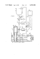
- FIG. 1 shows a device according to the invention in the circulation position.
- FIG. 2 shows a device according to the invention in the injection position.
- the above object is achieved by the method according to the invention in that the quantitative rate flow and the circulation pressure are controlled by adjusting the metering pump and the throttling means, the mixing process is then initiated and the injection presssure is measured and the measured value stored, the apparatus is switched back to circulation and the measured and stored value of the injection pressure acts as a new desired value for the circulation pressure, and the measuring and control process according to the previous steps is successively reintroduced.
- This iterative control process allows the rate of flow to be monitored automatically. Monitoring is carried out continuously and it is not necessary to interrupt the actual course of operation.
- the invention relates to a method of producing a reaction mixture from flowable components comprising:
- step (E) repeating steps (C) and (D) as often as necessary to attain both (i) a circulation pressure within ⁇ 2 bar of said predetermined circulation pressure and (ii) a quantitative rate of flow within said predetermined limits of said predetermined quantitative rate of flow, (F) once step (E) has been completed, stopping circulation step (A), and allowing said components to be mixed in said mix head,
- step (H) repeating the process, using the measured pressure from step (G) as said predetermined circulation pressure.
- the device according to the invention is based on one which, for each component, comprises:
- a needle nozzle with an associated stroke adjusting device is provided in the mix head, wherein the needle nozzle
- the adjusting members consist of servomotors with which the metering pump control device and the throttling means adjusting device can be actuated.
- the device according to the invention is illustrated purely schematically for one component in an embodiment.
- the device should be enlarged in a similar manner for supplying a second or any other component.
- a feed pipe 2 leads from a storage container 1 to a mixer head 3.
- the mixer head 3 consists of nozzles 4,5, a mixing chamber 6 (FIG. 2) and a cleaning device 7.
- a metering pump 8 is provided in the feed pipe 2 and is connected to a drive mechanism 9 operating at a constant speed.
- the metering pump 8 also has a control device 10 which is symbolized by an arrow and is connected to an adjusting member 11 designed as a servometer.
- the adjusting member 11 is connected via a pulse line 12 to a control computer 13.
- a pressure measuring device 14 arranged in the feed pipe 2 is coupled to a pressure displaying device 15 and connected via a pulse line 16 to the control computer 13.
- a quantitative flow-meter 17 which is coupled to a quantity-displaying device 18 and communicates via a pulse line 19 with the control computer 13, is also connected in the feed pipe 2.
- the feed pipe 2 opens into the nozzle housing 20.
- a nozzle needle 22 is guided in a passage 21, has a circulation channel 23 and seals the nozzle opening 24 pointing into the mixing chamber 6 in FIG. 1 but clears it in FIG. 2.
- a return pipe 25 branches from this housing 20 and opens into the storage container 1.
- the circulation channel 23 via the passage 21 represents the connection with the return pipe 25, while in FIG. 2, the nozzle needle 22 interrupts any circulation so that the component can enter the mixing chamber via the nozzle opening 24.
- the stroke of the nozzle needle 22 can be adjusted by means of a stroke adjusting device 26 designed as a set screw, so that the free cross-section of flow between the tip 27 of the nozzle needle 22 and the nozzle seat 28 can be adjusted.
- the nozzle needle 22 can be connected via a hydraulic motor 29.
- a throttling means 30 is arranged in the return pipe 25 and has an adjusting device 31 symbolized by an arrow.
- the adjusting device 31 is coupled to a servomotor acting as an adjusting member 32.
- the servomotor is connected via a pulse line 33 to the control computer 13.
- the cleaning device 7 consists of a housing 34 in which a cleaning piston 35 is guided. It is actuated by a hydraulic motor 36. In FIG. 1, the cleaning piston 35 is located in the ejection position and has displaced the mixing chamber while, in FIG. 2, it adopts the mixing position so that the mixing chamber 6 is formed in its guide passage 37.
- the throughput capacity of the metering pump depends on the counter-pressure.
- the flow rate Q is given as a function of the control path Rw of the metering pump adjusting device.
- the operating pressure is dependent on the adjusted path of the throttling means.
- the adjusting member 11 for the control path adjusting device 10 of the metering pump 8 and the adjusting member 32 for the adjusting device 31 of the throttle path of the throttling means 30 as well as the adjusting device designed as a stop screw 26 for the stroke of the injection nozzle needle 22 provide the regulating variable.
- the actual control process begins as the desired values are firstly fed into the control computer 13 which processes the control and regulating variables.
- the rate of flow of one component should be, for example, 10 kg/min with a maximum deviation of ⁇ 0.1 kg/min.
- the injection pressure should lie between 120 and 180 bar. That is, the pressure range at which the injection mixing is known to be sufficiently intensive, from experience of the mixture to be processed.
- the means value of the injection pressure range which is about 150 bar is advantageously selected as the predetermined pressure for the circulation.
- the actual pressure adjusted during control should be observed and regulated with an accuracy of 35 2 bar.
- a rough preselection of the adjusting members is firstly made when the device is switched to circulation.
- the adjusting motor 11 for the adjusting device 10 of the metering pump 8 travels over a control path of 2.3 mmm corresponding to a throughput of 9.4 kg/min.
- the adjusting motor 32 for the adjusting device 31 of the throttling means 30 travels over a path of 2.07 mm.
- An operating pressure at the pressure display device of from 15 to 138 bar is adjusted under these conditions.
- the pressure is firstly compensated. If the effective injection pressure is not within the predetermined pressure range of from 120 to 180 bar, the adjusting device 26 of the nozzle needle 22 has to be adjusted again manually. If the injection pressure is within the said pressure range, the pressure actually adjusted is recorded in the control computer 13 and, after switching back to circulation, acts as a new desired value or as a new control variable. In the above example, this value is 135 bar. The remaining circulation control steps now follow until the values lie within the new tolerance range. The device is then switched over to injection again and the injection pressure adjusted is recorded in the control computer 13.
- circulation pressure and injection pressure do not yet coincide, further regulation is made in circulation so that the last recorded value of the injection pressure acts as a new desired value for the circulation pressure. It is 130 bar in the example.
- the circulation pressure and injection pressure approach each other iteratively. Further equalization and control steps can be completed.
- uniformity in the pressure level is observed at the predetermined rate of flow with permitted deviations once the device has been switched to injection again. The device has thus approached the desired value iteratively after only three control and equalization processes. These values are compared, stored and adjusted in the case of each additional injection.
- the injection pressure is measured and stored after equalizing the rate of flow and the pressure in circulation with the injection pressure after switching over to injection. If the injection pressure lies within the predetermined injection pressure range, the circulation is equalized again with the measured stored value of the injection pressure. If the measured value of the injection pressure lies outside the predetermined range the control has to be interrupted and the nozzle adjusted again manually. The circulation is only equalized again afterwards.
Landscapes
- Engineering & Computer Science (AREA)
- Mechanical Engineering (AREA)
- Physics & Mathematics (AREA)
- General Physics & Mathematics (AREA)
- Automation & Control Theory (AREA)
- Injection Moulding Of Plastics Or The Like (AREA)
- Processing And Handling Of Plastics And Other Materials For Molding In General (AREA)
- Casting Or Compression Moulding Of Plastics Or The Like (AREA)
- Molding Of Porous Articles (AREA)
- Manufacture Of Porous Articles, And Recovery And Treatment Of Waste Products (AREA)
Abstract
The invention relates to a method and a device for producing a reaction mixture from flowable foam-forming or solid-forming components (preferably polyurethane forming components) which are conveyed continuously and are mixed together or are circulated. The quantity to be conveyed is preselected. The injection pressure is preselected and the circulatory pressure is measured for each component. The predetermined quantity and pressure to be conveyed as well as the measured value are preferably fed into a control computer during the circulation and the mixing process and are compared with actual values. Cavities are filled out with the reaction mixture produced and, in particular, molded articles are produced in molds.
Description
In the production of molded polyurethane products from flowable reactants to obtain an end product which is free from defects, the flow rates of the components which depend on various factors such as viscosity, temperature, pressure, must be monitored continuously. As these factors are limited by variations in the structure of the components and by tolerances in the mode of operation of the mixing device, it is very difficult to keep them completely constant. It is therefore necessary to keep the flow rate constant as these factors change.
With the known devices, the metering pumps are tested by allowing the quantity conveyed per unit time to flow out at a certain pressure and then weighing it at various adjustments of the pump control path. According to the pump characteristics determined in this way (which are based on the dependence of the quantity conveyed Q as a function (f) of the control path of the pumps) the mixing device is adjusted with respect to the correct, prescribed stoichiometric ratio. This occurs before production commences. The observance of these predetermined values cannot be checked during production. An entire time-consuming and expensive test run therefore must be repeated at certain intervals to give sufficient reliability in production. This test method is also accompanied by a large unreliability factor since the weight is measured only under atmospheric pressure. If one component contains a blowing agent, the blowing agent can escape under certain circumstances due to its low boiling point.
Attempts have been made to divide at least one component stream continuously into a main stream and a subsidiary stream, the subsidiary stream being brought to the same operating pressure as the main stream just before it is introduced into the mixing zone. The volumetric rate of flow of the subsidiary stream is then measured. The quantity by volume of the subsidiary stream which has passed through during a predetermined time interval is determined by measurement. The quantity by weight which has passed through during the same predetermined time interval is determined by weighing. The density of the component is determined as a quotient of the quantity by weight and the quantity by volume. The quantitative rate of flow of the main stream of the component is determined as the product of the density of the component and the volumetric rate of flow of the main stream. This mode of operation is very complex not only with regard to monitoring but also with regard to the apparatus.
The object of the invention is to provide a method and a device for the reliable, automatic regulation and monitoring of the rates of flow during the injection and circulation at predetermined pressures.
FIG. 1 shows a device according to the invention in the circulation position.
FIG. 2 shows a device according to the invention in the injection position.
The above object is achieved by the method according to the invention in that the quantitative rate flow and the circulation pressure are controlled by adjusting the metering pump and the throttling means, the mixing process is then initiated and the injection presssure is measured and the measured value stored, the apparatus is switched back to circulation and the measured and stored value of the injection pressure acts as a new desired value for the circulation pressure, and the measuring and control process according to the previous steps is successively reintroduced.
This iterative control process allows the rate of flow to be monitored automatically. Monitoring is carried out continuously and it is not necessary to interrupt the actual course of operation.
More particularly, the invention relates to a method of producing a reaction mixture from flowable components comprising:
(A) continuously circulating said components from storage containers via feed pipes to a mix head and back to said storage containers via return pipes, said feed pipes being provided with metering pumps and said return pipes being provided with adjustable throttling means,
(B) measuring the quantitative rate of flow of said components through said feed pipes and measuring the circulation pressure of the components through said return pipes,
(C) adjusting the throttling means so that the circulation pressure will be ±2 bar of a predetermined circulation pressure,
(D) if necessary, adjusting the metering pumps so that the quantitative rate of flow of components will be within predetermined limits of a predetermined quantitative rate of flow,
(E) repeating steps (C) and (D) as often as necessary to attain both (i) a circulation pressure within ±2 bar of said predetermined circulation pressure and (ii) a quantitative rate of flow within said predetermined limits of said predetermined quantitative rate of flow, (F) once step (E) has been completed, stopping circulation step (A), and allowing said components to be mixed in said mix head,
(G) measuring the pressure under which the components are mixed in said mix head,
(H) repeating the process, using the measured pressure from step (G) as said predetermined circulation pressure.
The device according to the invention is based on one which, for each component, comprises:
(a) a storage container, from which
(b) a feed pipe leads to a common mix head which
(c) contains a mixing chamber into which the feed pipe opens,
(d) a metering pump located in said pipe and provided with a control device,
(e) a pressure measuring device and
(f) a quantitative rate of flow-meter being arranged in the feed pipe, and in that
(g) a needle nozzle with an associated stroke adjusting device is provided in the mix head, wherein the needle nozzle
(h) has a circulation channel, and
(ia) connects the feed pipe to a return pipe in the circulation position,
(ib) connects the feed pipe to the mixing chamber in the mixing position, and wherein
(j) an adjustable throttling means is provided in the return pipe.
The novelty lies in the fact that
(k) the metering pump is provided with an adjusting member,
(l) the throttling means is provided with an adjusting member, and
(m) the adjusting members and the pressure measuring device are connected to a control computer.
The adjusting members consist of servomotors with which the metering pump control device and the throttling means adjusting device can be actuated.
The device according to the invention is illustrated purely schematically for one component in an embodiment.
The device should be enlarged in a similar manner for supplying a second or any other component.
A feed pipe 2 leads from a storage container 1 to a mixer head 3. The mixer head 3 consists of nozzles 4,5, a mixing chamber 6 (FIG. 2) and a cleaning device 7. A metering pump 8 is provided in the feed pipe 2 and is connected to a drive mechanism 9 operating at a constant speed. The metering pump 8 also has a control device 10 which is symbolized by an arrow and is connected to an adjusting member 11 designed as a servometer. The adjusting member 11 is connected via a pulse line 12 to a control computer 13. A pressure measuring device 14 arranged in the feed pipe 2 is coupled to a pressure displaying device 15 and connected via a pulse line 16 to the control computer 13. Finally, a quantitative flow-meter 17, which is coupled to a quantity-displaying device 18 and communicates via a pulse line 19 with the control computer 13, is also connected in the feed pipe 2. The feed pipe 2 opens into the nozzle housing 20. A nozzle needle 22 is guided in a passage 21, has a circulation channel 23 and seals the nozzle opening 24 pointing into the mixing chamber 6 in FIG. 1 but clears it in FIG. 2. A return pipe 25 branches from this housing 20 and opens into the storage container 1. In FIG. 1, the circulation channel 23 via the passage 21 represents the connection with the return pipe 25, while in FIG. 2, the nozzle needle 22 interrupts any circulation so that the component can enter the mixing chamber via the nozzle opening 24. The stroke of the nozzle needle 22 can be adjusted by means of a stroke adjusting device 26 designed as a set screw, so that the free cross-section of flow between the tip 27 of the nozzle needle 22 and the nozzle seat 28 can be adjusted. The nozzle needle 22 can be connected via a hydraulic motor 29. A throttling means 30 is arranged in the return pipe 25 and has an adjusting device 31 symbolized by an arrow. The adjusting device 31 is coupled to a servomotor acting as an adjusting member 32. The servomotor is connected via a pulse line 33 to the control computer 13. The cleaning device 7 consists of a housing 34 in which a cleaning piston 35 is guided. It is actuated by a hydraulic motor 36. In FIG. 1, the cleaning piston 35 is located in the ejection position and has displaced the mixing chamber while, in FIG. 2, it adopts the mixing position so that the mixing chamber 6 is formed in its guide passage 37.
The course of operation is illustrated below with reference to the device described above.
As already noted, the throughput capacity of the metering pump depends on the counter-pressure. The flow rate Q is given as a function of the control path Rw of the metering pump adjusting device. Moreover, the operating pressure is dependent on the adjusted path of the throttling means. These two functions Q=f (Rw) and p=f (s) now have to be brought into accord into terms of control. The pressure which can be read in bars on the display device 15 and the rate of flow which can be read in kg/m on the display device 18 are the control variables. The adjusting member 11 for the control path adjusting device 10 of the metering pump 8 and the adjusting member 32 for the adjusting device 31 of the throttle path of the throttling means 30 as well as the adjusting device designed as a stop screw 26 for the stroke of the injection nozzle needle 22 provide the regulating variable.
The actual control process begins as the desired values are firstly fed into the control computer 13 which processes the control and regulating variables.
The rate of flow of one component should be, for example, 10 kg/min with a maximum deviation of ±0.1 kg/min. The injection pressure should lie between 120 and 180 bar. That is, the pressure range at which the injection mixing is known to be sufficiently intensive, from experience of the mixture to be processed. The means value of the injection pressure range which is about 150 bar is advantageously selected as the predetermined pressure for the circulation. The actual pressure adjusted during control should be observed and regulated with an accuracy of 35 2 bar.
A rough preselection of the adjusting members is firstly made when the device is switched to circulation. The adjusting motor 11 for the adjusting device 10 of the metering pump 8 travels over a control path of 2.3 mmm corresponding to a throughput of 9.4 kg/min. The adjusting motor 32 for the adjusting device 31 of the throttling means 30 travels over a path of 2.07 mm. An operating pressure at the pressure display device of from 15 to 138 bar is adjusted under these conditions.
Control now begins in accordance with the following diagram:
__________________________________________________________________________
Circulation
Rough preselection
               Rough preselection
                              Injection (mixing)
metering pump  throttling means
                              Rough preselection nozzle
__________________________________________________________________________
 ##STR1##
 ##STR2##
 ##STR3##
 ##STR4##
 ##STR5##
 ##STR6##
                                              ##STR7##
 ##STR8##
                                              ##STR9##
 ##STR10##
                                              ##STR11##
 ##STR12##
                                              ##STR13##
__________________________________________________________________________
As shown by the circulation control steps, a value of Q=10.0 kg/min and p=148 bar, which lies within the permitted deviations, has been adjusted after the 4th control step.
After switching over to injection so that the mixing process is initiated, the pressure is firstly compensated. If the effective injection pressure is not within the predetermined pressure range of from 120 to 180 bar, the adjusting device 26 of the nozzle needle 22 has to be adjusted again manually. If the injection pressure is within the said pressure range, the pressure actually adjusted is recorded in the control computer 13 and, after switching back to circulation, acts as a new desired value or as a new control variable. In the above example, this value is 135 bar. The remaining circulation control steps now follow until the values lie within the new tolerance range. The device is then switched over to injection again and the injection pressure adjusted is recorded in the control computer 13. If the circulation pressure and injection pressure do not yet coincide, further regulation is made in circulation so that the last recorded value of the injection pressure acts as a new desired value for the circulation pressure. It is 130 bar in the example. The circulation pressure and injection pressure approach each other iteratively. Further equalization and control steps can be completed. In the example described above, uniformity in the pressure level is observed at the predetermined rate of flow with permitted deviations once the device has been switched to injection again. The device has thus approached the desired value iteratively after only three control and equalization processes. These values are compared, stored and adjusted in the case of each additional injection.
In this way, the injection pressure is measured and stored after equalizing the rate of flow and the pressure in circulation with the injection pressure after switching over to injection. If the injection pressure lies within the predetermined injection pressure range, the circulation is equalized again with the measured stored value of the injection pressure. If the measured value of the injection pressure lies outside the predetermined range the control has to be interrupted and the nozzle adjusted again manually. The circulation is only equalized again afterwards.
A constant check of the values is thus provided and deviations of any type, of the type which might occur, for example, due to a change in the viscosity of one component are inevitably controlled out immediately.
Claims (1)
1. A device for producing a reaction mixture from flowable foam-forming or solid-forming components, which, for each component comprise:
(a) a storage container, from which
(b) a feed pipe leads to a common mix head which
(c) contains a mixing chamber into which the feed pipe opens,
(d) a metering pump with an adjustable output, a pressure measuring device and a quantitative rate of flow meter being arranged in the feed pipe, and in that
(e) a needle nozzle and an exteriorly-controlled, hydraulically-movable needle with an associated stroke adjusting device is provided in the mix head,
(f) wherein the needle nozzle,
(g) has a circulation channel, and
(ga) connects the feed pipe to a return pipe in the circulation position,
(gb) connects the feed pipe to the mixing chamber in the mixing position, and wherein
(h) an adjustable throttling means is provided in the return pipe,
characterized in that
(i) the metering pump is provided with an adjusting member,
(j) the throttling means is provided with an adjusting member, and that
(k) the adjusting members, the flow meter and the pressure measuring device are connected to a control computer.
Applications Claiming Priority (2)
| Application Number | Priority Date | Filing Date | Title |
|---|---|---|---|
| DE2936223 | 1979-09-07 | ||
| DE19792936223 DE2936223A1 (en) | 1979-09-07 | 1979-09-07 | METHOD AND DEVICE FOR PRODUCING A REACTION MIXTURE FROM FLOWABLE, FOAM OR SOLID COMPONENTS |
Related Child Applications (1)
| Application Number | Title | Priority Date | Filing Date |
|---|---|---|---|
| US06/450,414 Division US4448902A (en) | 1979-09-07 | 1982-12-16 | Method and a device for the production of a reaction mixture from flowable foam-forming or solid-forming components |
Publications (1)
| Publication Number | Publication Date |
|---|---|
| US4399104A true US4399104A (en) | 1983-08-16 |
Family
ID=6080318
Family Applications (2)
| Application Number | Title | Priority Date | Filing Date |
|---|---|---|---|
| US06/183,487 Expired - Lifetime US4399104A (en) | 1979-09-07 | 1980-09-02 | Device for the production of a reaction mixture from flowable foam-forming or solid-forming components |
| US06/450,414 Expired - Lifetime US4448902A (en) | 1979-09-07 | 1982-12-16 | Method and a device for the production of a reaction mixture from flowable foam-forming or solid-forming components |
Family Applications After (1)
| Application Number | Title | Priority Date | Filing Date |
|---|---|---|---|
| US06/450,414 Expired - Lifetime US4448902A (en) | 1979-09-07 | 1982-12-16 | Method and a device for the production of a reaction mixture from flowable foam-forming or solid-forming components |
Country Status (5)
| Country | Link |
|---|---|
| US (2) | US4399104A (en) |
| EP (1) | EP0025871B1 (en) |
| JP (1) | JPS5644640A (en) |
| AT (1) | ATE2883T1 (en) |
| DE (2) | DE2936223A1 (en) |
Cited By (24)
| Publication number | Priority date | Publication date | Assignee | Title |
|---|---|---|---|---|
| US4442070A (en) * | 1981-03-26 | 1984-04-10 | Maschinenfabrik Hennecke Gmbh | Apparatus for the production of a flowable reaction mixture |
| US4490048A (en) * | 1982-01-22 | 1984-12-25 | Elastogran Maschinenbau Gmbh | Apparatus for producing a preferably chemically reactive mixture from two or more plastics components |
| US4695166A (en) * | 1985-06-21 | 1987-09-22 | Bayer Aktiengesellschaft | Piston metering device for the production of plastic material from at least two flowable reaction components |
| US4854713A (en) * | 1987-11-10 | 1989-08-08 | Krauss-Maffei A.G. | Impingement mixing device with pressure controlled nozzle adjustment |
| US4886643A (en) * | 1986-05-15 | 1989-12-12 | Battenfeld Maschinenfabriken Gmbh | Apparatus for proportioning reaction mixtures |
| US4904451A (en) * | 1988-08-18 | 1990-02-27 | Maschinenfabrik Hennecke Gmbh | Process and device for the preparation of flowable reaction mixtures |
| US4944599A (en) * | 1987-11-10 | 1990-07-31 | Krauss-Maffei A.G. | Impingement mixing device with pressure controlled nozzle adjustment |
| US4966466A (en) * | 1987-11-10 | 1990-10-30 | Krauss-Maffei A.G. | Impingement mixing device with pressure controlled nozzle adjustment |
| US5270013A (en) * | 1992-05-06 | 1993-12-14 | Decker Herman W | Reactive fluid mixing head |
| US5366287A (en) * | 1991-08-31 | 1994-11-22 | Adrian Verstallen | Apparatus for homogenizing essentially immiscible liquids for forming an emulsion |
| US5443797A (en) * | 1991-02-06 | 1995-08-22 | Maschinenfabrik Hennecke Gmbh | Process and apparatus for the production of a flowable reaction mixture from at least two flowable reactive components |
| US5453250A (en) * | 1992-07-16 | 1995-09-26 | Bayer Aktiengesellschaft | Apparatus for the preparation of a flowable reaction mixture |
| US5482369A (en) * | 1993-02-08 | 1996-01-09 | Verstallen; Adrian | Process for homogenizing essentially immiscible liquids for forming an emulsion |
| US5558249A (en) * | 1993-05-05 | 1996-09-24 | E. I. Du Pont De Nemours And Company | Precision liquid addition device |
| US5615949A (en) * | 1995-08-08 | 1997-04-01 | Woodbridge Foam Corporation | High pressure mixing system and process for producing foamed isocyanate-based polymers containing filler material |
| US20030213520A1 (en) * | 2002-04-12 | 2003-11-20 | Bayer Aktiengesellschaft | Apparatus for metered addition of gases |
| US20040130049A1 (en) * | 2003-01-07 | 2004-07-08 | Michael Begemann | Process for producing polyurethane moldings |
| EP1445092A1 (en) * | 2003-02-05 | 2004-08-11 | KLÖCKNER DESMA SCHUHMASCHINEN GmbH | Pressure adjustment device of polyurethane injection molding machines |
| EP1447206A1 (en) * | 2003-02-14 | 2004-08-18 | Hennecke GmbH | Process for manufacturing molded polyurethane parts |
| WO2005097477A1 (en) * | 2004-04-05 | 2005-10-20 | Faculdade De Engenharia Da Universidade Do Porto | Production process of plastic parts by reaction injection moulding, and related head device |
| US20080085219A1 (en) * | 2006-10-05 | 2008-04-10 | Beebe David J | Microfluidic platform and method |
| WO2011066095A1 (en) * | 2009-11-24 | 2011-06-03 | Dow Global Technologies Inc. | Fluid mixing and dispensing apparatus and process |
| CN101652187B (en) * | 2007-04-05 | 2013-05-01 | 亨内克股份有限公司 | Method and device for producing molded parts containing polyurethane layers |
| US8777478B2 (en) | 2008-11-27 | 2014-07-15 | Inoac Corporation | Mixing head apparatus for high agitation and smooth flow of liquid blend and molding method using the same |
Families Citing this family (23)
| Publication number | Priority date | Publication date | Assignee | Title |
|---|---|---|---|---|
| DE3021095C2 (en) * | 1980-06-04 | 1983-12-22 | Maschinenfabrik Hennecke Gmbh, 5090 Leverkusen | Method and device for producing a solid or foam-forming reaction mixture from at least two flowable reaction components |
| IT1135030B (en) * | 1981-01-14 | 1986-08-20 | Afros Spa | REMOTE CONTROLLED INJECTOR FOR MIXING HEADS OF CHEMICAL COMPONENTS TO FEED TO A MOLD |
| IT1135043B (en) * | 1981-01-15 | 1986-08-20 | Afros Spa | MIXING HEAD FOR REACTIVE CHEMICALS, WITH REMOTE CONTROLLED INJECTORS |
| DE3120974C2 (en) * | 1981-05-26 | 1987-03-26 | Fa. Hans Wilmsen, 4300 Essen | Device for filling cavities with aminoplast foam |
| DE3239551A1 (en) * | 1982-10-26 | 1984-04-26 | Krauss-Maffei AG, 8000 München | DEVICE FOR DELIVERING A PARTICULARLY CHEMICALLY REACTIVE PLASTIC MIXTURE TO A MOLD (MIXING HEAD) |
| US4526907A (en) * | 1983-05-07 | 1985-07-02 | Basf Aktiengesellschaft | Process and device for the preparation of a reaction mixture of at least two components for the production of foams |
| JPH0320092Y2 (en) * | 1985-03-22 | 1991-04-30 | ||
| US4590218A (en) * | 1985-06-19 | 1986-05-20 | The O'brien Corporation | Method and apparatus for forming a chemical composition from cross-linking components and product of the method |
| DE3637896A1 (en) * | 1986-11-06 | 1988-06-16 | Krauss Maffei Ag | Process for mixing and injecting a two-component synthetic resin |
| US5154088A (en) * | 1990-07-24 | 1992-10-13 | The Dow Chemical Company | Apparatuses and methods for incorporating blowing agents into liquids for the production of polymer foams and for measuring the volumetric expansion potential of mixtures thereof |
| US5119668A (en) * | 1990-07-24 | 1992-06-09 | The Dow Chemical Company | Apparatuses and methods for incorporating blowing agents into liquids for the production of polymer foams and for measuring the volumetric expansion potential of mixtures thereof |
| JPH04151211A (en) * | 1990-10-15 | 1992-05-25 | Iketsukusu Kogyo:Kk | Injection port device for cast molding machine |
| US5271521A (en) * | 1991-01-11 | 1993-12-21 | Nordson Corporation | Method and apparatus for compensating for changes in viscosity in a two-component dispensing system |
| CA2057948A1 (en) * | 1991-01-11 | 1992-07-12 | James W. Schmitkons | Method and apparatus for metering flow of a two-component dispensing system |
| DE4119966C2 (en) * | 1991-06-18 | 1996-02-08 | Spuehl Ag | Measuring device for detecting the gas load of a plastic component |
| JP3725621B2 (en) | 1996-06-21 | 2005-12-14 | 同和鉱業株式会社 | High-purity silver wire for recording or sound or image transmission |
| US6627149B1 (en) | 1996-06-21 | 2003-09-30 | Dowa Mining Co., Ltd. | High-purity silver wires for use in recording, acoustic or image transmission applications |
| CA2397963A1 (en) * | 2000-01-20 | 2001-07-26 | Krauss-Maffei Kunststofftechnik Gmbh | Injection nozzle for mixing heads of reaction molding machines |
| CN102009445A (en) * | 2010-09-21 | 2011-04-13 | 上海大学 | Full-automatic vacuum molding control system and method |
| DE102010043329A1 (en) * | 2010-11-03 | 2012-05-03 | Bayer Materialscience Aktiengesellschaft | Process for the production of foamed moldings |
| JP7021575B2 (en) * | 2018-03-16 | 2022-02-17 | マツダ株式会社 | Multi-liquid mixer |
| JP7102811B2 (en) * | 2018-03-16 | 2022-07-20 | マツダ株式会社 | Fluid material supply equipment |
| DE102024105222B3 (en) * | 2024-02-23 | 2025-07-24 | Hennecke Gmbh | Process and device for the production of polyurethane components |
Citations (4)
| Publication number | Priority date | Publication date | Assignee | Title |
|---|---|---|---|---|
| US4013391A (en) * | 1974-03-20 | 1977-03-22 | Bayer Aktiengesellschaft | Mixing apparatus combined with a molding tool |
| US4198374A (en) * | 1975-01-03 | 1980-04-15 | Societe Anonyme De Telecommunications | Volatile liquid supply equipment and processes for introducing volatile cross-linking agents into polyolefin compounds and for the extrusion of cross-linkable polyolefin compounds |
| US4239732A (en) * | 1979-04-13 | 1980-12-16 | The Martin Sweets Company, Inc. | High velocity mixing system |
| US4265858A (en) * | 1976-03-31 | 1981-05-05 | Nordson Corporation | Metering and mixing apparatus for multiple component |
Family Cites Families (11)
| Publication number | Priority date | Publication date | Assignee | Title |
|---|---|---|---|---|
| US3539784A (en) * | 1967-07-31 | 1970-11-10 | Texaco Inc | Process instrumentation and control through measurements of time-separated process variables |
| US3857550A (en) * | 1972-04-20 | 1974-12-31 | Bayer Ag | Machine for producing foams, homogeneous or structural materials from at least two liquid reaction components |
| US3843099A (en) * | 1973-02-26 | 1974-10-22 | Usm Corp | Instantaneous rationing means |
| DE2364922A1 (en) * | 1973-12-28 | 1975-07-17 | Mirabed Ag | Plastics components fed to mixing head are weigh-batched - to achieve high accuracy independent of viscosity or other fluctuations |
| DE2527378B2 (en) * | 1975-06-19 | 1977-07-14 | Bayer Ag, 5090 Leverkusen | METHOD AND DEVICE FOR DOSING MULTI-COMPONENT LIQUID SYSTEMS |
| DE2529735C3 (en) * | 1975-07-01 | 1978-06-08 | Max-Planck-Gesellschaft Zur Foerderung Der Wissenschaften E.V., 3400 Goettingen | Corpuscular beam microscope, in particular electron microscope, with adjustment devices for changing the position of the object to be imaged and a method for operation |
| DE2724132C3 (en) * | 1977-05-27 | 1980-09-25 | Bayer Ag, 5090 Leverkusen | Method and apparatus for producing a foam-forming reaction mixture |
| DE2758096C2 (en) * | 1977-12-24 | 1984-05-24 | Behr, Hans, 7000 Stuttgart | Method and device for automatic dynamic dosing of at least one liquid component of a mixed liquid |
| DE2805946A1 (en) * | 1978-02-13 | 1979-08-16 | Bayer Ag | DEVICE FOR DOSING AT LEAST TWO FLOWABLE REACTION COMPONENTS IN A MIXING CHAMBER |
| US4376172A (en) * | 1982-02-01 | 1983-03-08 | Cincinnati Milacron Inc. | Closed loop control of compressible fluid addition to a mixture of such fluid and a liquid |
| US4396729A (en) * | 1982-04-23 | 1983-08-02 | Texaco Inc. | Reaction injection molded elastomer containing an internal mold release made by a two-stream system |
-
1979
- 1979-09-07 DE DE19792936223 patent/DE2936223A1/en not_active Withdrawn
-
1980
- 1980-08-16 EP EP80104893A patent/EP0025871B1/en not_active Expired
- 1980-08-16 AT AT80104893T patent/ATE2883T1/en active
- 1980-08-16 DE DE8080104893T patent/DE3062536D1/en not_active Expired
- 1980-09-02 US US06/183,487 patent/US4399104A/en not_active Expired - Lifetime
- 1980-09-05 JP JP12247080A patent/JPS5644640A/en active Granted
-
1982
- 1982-12-16 US US06/450,414 patent/US4448902A/en not_active Expired - Lifetime
Patent Citations (4)
| Publication number | Priority date | Publication date | Assignee | Title |
|---|---|---|---|---|
| US4013391A (en) * | 1974-03-20 | 1977-03-22 | Bayer Aktiengesellschaft | Mixing apparatus combined with a molding tool |
| US4198374A (en) * | 1975-01-03 | 1980-04-15 | Societe Anonyme De Telecommunications | Volatile liquid supply equipment and processes for introducing volatile cross-linking agents into polyolefin compounds and for the extrusion of cross-linkable polyolefin compounds |
| US4265858A (en) * | 1976-03-31 | 1981-05-05 | Nordson Corporation | Metering and mixing apparatus for multiple component |
| US4239732A (en) * | 1979-04-13 | 1980-12-16 | The Martin Sweets Company, Inc. | High velocity mixing system |
Cited By (30)
| Publication number | Priority date | Publication date | Assignee | Title |
|---|---|---|---|---|
| US4442070A (en) * | 1981-03-26 | 1984-04-10 | Maschinenfabrik Hennecke Gmbh | Apparatus for the production of a flowable reaction mixture |
| US4490048A (en) * | 1982-01-22 | 1984-12-25 | Elastogran Maschinenbau Gmbh | Apparatus for producing a preferably chemically reactive mixture from two or more plastics components |
| US4695166A (en) * | 1985-06-21 | 1987-09-22 | Bayer Aktiengesellschaft | Piston metering device for the production of plastic material from at least two flowable reaction components |
| US4886643A (en) * | 1986-05-15 | 1989-12-12 | Battenfeld Maschinenfabriken Gmbh | Apparatus for proportioning reaction mixtures |
| US4944599A (en) * | 1987-11-10 | 1990-07-31 | Krauss-Maffei A.G. | Impingement mixing device with pressure controlled nozzle adjustment |
| US4854713A (en) * | 1987-11-10 | 1989-08-08 | Krauss-Maffei A.G. | Impingement mixing device with pressure controlled nozzle adjustment |
| US4966466A (en) * | 1987-11-10 | 1990-10-30 | Krauss-Maffei A.G. | Impingement mixing device with pressure controlled nozzle adjustment |
| US4904451A (en) * | 1988-08-18 | 1990-02-27 | Maschinenfabrik Hennecke Gmbh | Process and device for the preparation of flowable reaction mixtures |
| US5443797A (en) * | 1991-02-06 | 1995-08-22 | Maschinenfabrik Hennecke Gmbh | Process and apparatus for the production of a flowable reaction mixture from at least two flowable reactive components |
| US5366287A (en) * | 1991-08-31 | 1994-11-22 | Adrian Verstallen | Apparatus for homogenizing essentially immiscible liquids for forming an emulsion |
| US5270013A (en) * | 1992-05-06 | 1993-12-14 | Decker Herman W | Reactive fluid mixing head |
| US5453250A (en) * | 1992-07-16 | 1995-09-26 | Bayer Aktiengesellschaft | Apparatus for the preparation of a flowable reaction mixture |
| US5482369A (en) * | 1993-02-08 | 1996-01-09 | Verstallen; Adrian | Process for homogenizing essentially immiscible liquids for forming an emulsion |
| US5558249A (en) * | 1993-05-05 | 1996-09-24 | E. I. Du Pont De Nemours And Company | Precision liquid addition device |
| US5615949A (en) * | 1995-08-08 | 1997-04-01 | Woodbridge Foam Corporation | High pressure mixing system and process for producing foamed isocyanate-based polymers containing filler material |
| US20030213520A1 (en) * | 2002-04-12 | 2003-11-20 | Bayer Aktiengesellschaft | Apparatus for metered addition of gases |
| CN100343042C (en) * | 2003-01-07 | 2007-10-17 | 亨内克股份有限公司 | Method for manufacturing polyurethane moulding compound product |
| US20040130049A1 (en) * | 2003-01-07 | 2004-07-08 | Michael Begemann | Process for producing polyurethane moldings |
| EP1437210A1 (en) * | 2003-01-07 | 2004-07-14 | Hennecke GmbH | Process for producing molded polyurethane articles |
| US7404916B2 (en) * | 2003-01-07 | 2008-07-29 | Hennecke Gmbh | Process for producing polyurethane moldings |
| EP1445092A1 (en) * | 2003-02-05 | 2004-08-11 | KLÖCKNER DESMA SCHUHMASCHINEN GmbH | Pressure adjustment device of polyurethane injection molding machines |
| US20040217513A1 (en) * | 2003-02-14 | 2004-11-04 | Jurgen Wirth | Process for producing polyurethane moldings |
| EP1447206A1 (en) * | 2003-02-14 | 2004-08-18 | Hennecke GmbH | Process for manufacturing molded polyurethane parts |
| WO2005097477A1 (en) * | 2004-04-05 | 2005-10-20 | Faculdade De Engenharia Da Universidade Do Porto | Production process of plastic parts by reaction injection moulding, and related head device |
| US20080206392A1 (en) * | 2004-04-05 | 2008-08-28 | Faculdade De Engenharia Da Universidade Do Porto | Production Process of Plastic Parts by Reaction Injection Moulding, and Related Head Device |
| US7708918B2 (en) | 2004-04-05 | 2010-05-04 | Faculdade De Engenharia Da Universidade Do Porto | Production process of plastic parts by reaction injection moulding, and related head device |
| US20080085219A1 (en) * | 2006-10-05 | 2008-04-10 | Beebe David J | Microfluidic platform and method |
| CN101652187B (en) * | 2007-04-05 | 2013-05-01 | 亨内克股份有限公司 | Method and device for producing molded parts containing polyurethane layers |
| US8777478B2 (en) | 2008-11-27 | 2014-07-15 | Inoac Corporation | Mixing head apparatus for high agitation and smooth flow of liquid blend and molding method using the same |
| WO2011066095A1 (en) * | 2009-11-24 | 2011-06-03 | Dow Global Technologies Inc. | Fluid mixing and dispensing apparatus and process |
Also Published As
| Publication number | Publication date |
|---|---|
| EP0025871A1 (en) | 1981-04-01 |
| DE3062536D1 (en) | 1983-05-05 |
| EP0025871B1 (en) | 1983-03-30 |
| ATE2883T1 (en) | 1983-04-15 |
| JPS5644640A (en) | 1981-04-23 |
| US4448902A (en) | 1984-05-15 |
| DE2936223A1 (en) | 1981-03-19 |
| JPS6323891B2 (en) | 1988-05-18 |
Similar Documents
| Publication | Publication Date | Title |
|---|---|---|
| US4399104A (en) | Device for the production of a reaction mixture from flowable foam-forming or solid-forming components | |
| US4211523A (en) | Gas-flow control apparatus for equipment for producing foamed plastic | |
| EP0344501B1 (en) | Method and device for continuously charging a liquid reactive component with a gas for making a foamy reactive mixture | |
| US4854713A (en) | Impingement mixing device with pressure controlled nozzle adjustment | |
| DE69026683T2 (en) | Method and apparatus for regulating the gas content in a foam material | |
| US4314963A (en) | Method and a device for producing shaped articles from a multi-component reaction mixture | |
| US3984510A (en) | Ratio controlled mixing of liquids | |
| US4170319A (en) | Apparatus for controlling fluid flow in a fluid delivery and mixing system utilizing positive displacement devices | |
| US4966466A (en) | Impingement mixing device with pressure controlled nozzle adjustment | |
| EP0473791A1 (en) | Method of controlling injection of injection molding machine | |
| EP0110244B1 (en) | Method of and apparatus for preparing a fluid foaming reaction mixture from fluid components | |
| US3706516A (en) | An apparatus for producing foam sections from components that react quickly with one another when mixed | |
| EP0217400B1 (en) | Apparatus for precisely measuring and supplying liquid | |
| US5551486A (en) | Method and equipment for filing casting molds with casting resin or similarly casting-ready liquid media | |
| DE2724132A1 (en) | METHOD AND APPARATUS FOR PREPARING A FOAM-FORMING REACTION MIXTURE | |
| US4944599A (en) | Impingement mixing device with pressure controlled nozzle adjustment | |
| CA1099064A (en) | Moulding of plastics | |
| CA2074170A1 (en) | Moulding processes and apparatus | |
| KR20040074000A (en) | Process for Producing Polyurethane Moldings | |
| US2974830A (en) | Mixing device | |
| EP0080643A2 (en) | Method for producing a free flowing, homogeneous or foam material from a reactive mixture | |
| US4572820A (en) | Process and apparatus for the production of a flowable reaction mixture | |
| JPS645980B2 (en) | ||
| DE2543088A1 (en) | Control system for injection moulding machine - regulates resin temp., back pressure and throughput at each stage of extrusion stroke | |
| US4304125A (en) | Method and apparatus for measuring fuel flow |
Legal Events
| Date | Code | Title | Description |
|---|---|---|---|
| STCF | Information on status: patent grant |
Free format text: PATENTED CASE |