EP0344501B1 - Method and device for continuously charging a liquid reactive component with a gas for making a foamy reactive mixture - Google Patents
Method and device for continuously charging a liquid reactive component with a gas for making a foamy reactive mixture Download PDFInfo
- Publication number
- EP0344501B1 EP0344501B1 EP89108654A EP89108654A EP0344501B1 EP 0344501 B1 EP0344501 B1 EP 0344501B1 EP 89108654 A EP89108654 A EP 89108654A EP 89108654 A EP89108654 A EP 89108654A EP 0344501 B1 EP0344501 B1 EP 0344501B1
- Authority
- EP
- European Patent Office
- Prior art keywords
- gas
- component
- hollow
- reaction component
- agitator
- Prior art date
- Legal status (The legal status is an assumption and is not a legal conclusion. Google has not performed a legal analysis and makes no representation as to the accuracy of the status listed.)
- Expired - Lifetime
Links
- 239000007788 liquid Substances 0.000 title claims abstract 8
- 238000000034 method Methods 0.000 title claims description 10
- 239000000203 mixture Substances 0.000 title description 3
- 238000004519 manufacturing process Methods 0.000 claims abstract description 7
- 230000009969 flowable effect Effects 0.000 claims description 10
- 239000011541 reaction mixture Substances 0.000 claims description 5
- 238000005187 foaming Methods 0.000 claims 3
- 238000007599 discharging Methods 0.000 claims 2
- 229920005830 Polyurethane Foam Polymers 0.000 abstract description 2
- 239000006260 foam Substances 0.000 abstract description 2
- 239000011496 polyurethane foam Substances 0.000 abstract description 2
- 239000000155 melt Substances 0.000 abstract 1
- 239000007789 gas Substances 0.000 description 41
- 230000001105 regulatory effect Effects 0.000 description 3
- 238000003958 fumigation Methods 0.000 description 2
- 239000000654 additive Substances 0.000 description 1
- 238000011088 calibration curve Methods 0.000 description 1
- 230000001276 controlling effect Effects 0.000 description 1
- 238000001739 density measurement Methods 0.000 description 1
- 239000000945 filler Substances 0.000 description 1
- 239000012948 isocyanate Substances 0.000 description 1
- 150000002513 isocyanates Chemical class 0.000 description 1
- 229920005862 polyol Polymers 0.000 description 1
- 150000003077 polyols Chemical class 0.000 description 1
Images

Classifications
-
- B—PERFORMING OPERATIONS; TRANSPORTING
- B29—WORKING OF PLASTICS; WORKING OF SUBSTANCES IN A PLASTIC STATE IN GENERAL
- B29C—SHAPING OR JOINING OF PLASTICS; SHAPING OF MATERIAL IN A PLASTIC STATE, NOT OTHERWISE PROVIDED FOR; AFTER-TREATMENT OF THE SHAPED PRODUCTS, e.g. REPAIRING
- B29C67/00—Shaping techniques not covered by groups B29C39/00 - B29C65/00, B29C70/00 or B29C73/00
- B29C67/24—Shaping techniques not covered by groups B29C39/00 - B29C65/00, B29C70/00 or B29C73/00 characterised by the choice of material
- B29C67/246—Moulding high reactive monomers or prepolymers, e.g. by reaction injection moulding [RIM], liquid injection moulding [LIM]
-
- B—PERFORMING OPERATIONS; TRANSPORTING
- B29—WORKING OF PLASTICS; WORKING OF SUBSTANCES IN A PLASTIC STATE IN GENERAL
- B29B—PREPARATION OR PRETREATMENT OF THE MATERIAL TO BE SHAPED; MAKING GRANULES OR PREFORMS; RECOVERY OF PLASTICS OR OTHER CONSTITUENTS OF WASTE MATERIAL CONTAINING PLASTICS
- B29B7/00—Mixing; Kneading
- B29B7/74—Mixing; Kneading using other mixers or combinations of mixers, e.g. of dissimilar mixers ; Plant
- B29B7/7404—Mixing devices specially adapted for foamable substances
- B29B7/7409—Mixing devices specially adapted for foamable substances with supply of gas
- B29B7/7414—Mixing devices specially adapted for foamable substances with supply of gas with rotatable stirrer, e.g. using an intermeshing rotor-stator system
-
- B—PERFORMING OPERATIONS; TRANSPORTING
- B29—WORKING OF PLASTICS; WORKING OF SUBSTANCES IN A PLASTIC STATE IN GENERAL
- B29B—PREPARATION OR PRETREATMENT OF THE MATERIAL TO BE SHAPED; MAKING GRANULES OR PREFORMS; RECOVERY OF PLASTICS OR OTHER CONSTITUENTS OF WASTE MATERIAL CONTAINING PLASTICS
- B29B7/00—Mixing; Kneading
- B29B7/74—Mixing; Kneading using other mixers or combinations of mixers, e.g. of dissimilar mixers ; Plant
- B29B7/7404—Mixing devices specially adapted for foamable substances
- B29B7/7433—Plants
-
- Y—GENERAL TAGGING OF NEW TECHNOLOGICAL DEVELOPMENTS; GENERAL TAGGING OF CROSS-SECTIONAL TECHNOLOGIES SPANNING OVER SEVERAL SECTIONS OF THE IPC; TECHNICAL SUBJECTS COVERED BY FORMER USPC CROSS-REFERENCE ART COLLECTIONS [XRACs] AND DIGESTS
- Y10—TECHNICAL SUBJECTS COVERED BY FORMER USPC
- Y10S—TECHNICAL SUBJECTS COVERED BY FORMER USPC CROSS-REFERENCE ART COLLECTIONS [XRACs] AND DIGESTS
- Y10S261/00—Gas and liquid contact apparatus
- Y10S261/26—Foam
Definitions
- the invention relates to a method and a device for the continuous loading of at least one flowable reaction component with gas for the production of a foam-forming, flowable reaction mixture, in that the gas is dispersed into the reaction component in a gassing container by means of a hollow stirrer and the gas-loaded reaction component of the mixture with the mixture other reaction component is supplied, as known from DE-A1-34 34 443.
- the object is therefore to create a method and a device with which even the smallest amounts of gas can be dispersed in at least one of the reaction components in the correct ratio.
- This object is achieved in that both the reaction component and the gas are metered to the gassing tank, the amount of gas supplied per unit of time being kept constant by continuously measuring the supplied mass flow of the gas, comparing it with a predetermined target value and in terms of compliance with the Setpoint is controlled, and that the same amount of gas per unit of time is introduced into the reaction component by controlling the speed of the hollow stirrer.
- the speed of the hollow stirrer is regulated by keeping the level in the gassing tank constant.
- the speed of the hollow stirrer is regulated by measuring the amount of gas flowing to the gassing container.
- the new method is particularly suitable for the addition of gas fractions below the saturation point of the fumigated component; but it can also be used in the same way for loading the reaction components with larger amounts of gas.
- the new method can be modified also apply to the premixing of two or more different gases in a certain ratio.
- the new device for the continuous loading of at least one flowable reaction component with gas for the production of a foam-forming, flowable reaction mixture is based on a gassing container with a hollow stirrer having a speed-controllable drive, this hollow stirrer having a gas suction opening located above the level; a supply line for the non-fumigated component, a discharge line for the fumigated component and a gas supply line opening above the level.
- a control device is arranged in the gas supply line, which consists of a flow control valve with an actuator and a mass flow meter for the supplied gas connected to it. and that a further control device is provided, which consists of a level measuring device and an associated speed controller, which on the other hand is connected to the hollow stirrer drive.
- the usual, previously customary metering pumps, such as axial and radial piston pumps or, in particular for filler-containing components, piston metering devices are suitable as metering devices for the reaction component.
- the "digital operating and display device" type 147 A from the company is particularly suitable as a gas mass flow meter.
- the new device has the particular advantage that it reacts faster than the known ones, which work on the principle of density measurement.
- Level measuring devices are also known in a wide variety of embodiments. Those that allow an absolutely constant adjustment of the level are quite complex. However, those are also suitable which allow a constant keeping between two limit values, provided the limit value transmitters can be set to a sufficiently narrow interval with regard to the required accuracy of the gassing.
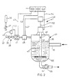
- a gassing container 1 is provided with a feed line 2 for gas, a feed line 3 for a reaction component to be gassed and with a discharge line 4 for the fumigated reaction component.
- the feed line 1 opens into the gassing container 1 above the level 5. It is connected to a gas source 6.
- a pressure reducing valve 7 and a regulating device 8 are arranged in the gas supply line 2, as seen in the flow direction. It consists of a flow control valve 9 with actuator 10 and a mass flow meter 11. From the latter leads a pulse line 12 to the actuator 10 of the flow control valve 9 and a pulse line 13 to a display panel 14.
- the mass flow meter 11 contains a transducer and is adjustable to a desired target value.
- a hollow stirrer 15 is arranged in the gassing container 1. Its suction opening 16 is provided above the level 5.
- a control device 17 is also assigned to this hollow stirrer 15. It consists of a level measuring device 18 arranged on the gassing container 1, which contains a transducer, as well as a speed controller 19 and the drive 20 of the hollow stirrer 15 The level measuring device 18 is connected to the display panel 14 via a further pulse line 23. A pulse line 24 also leads from the drive 20 to the display panel 14.
- the level measuring device 18 contains two limit switches between which the level mirror 5 is kept constant.
- a metering pump 25 is arranged in the feed line 3, which opens below the level 5.
- the discharge line 4 leads to the bottom 26 of the gassing container 1 and leads to a mixing head, not shown.
- the metering pump 25 can also be arranged in the discharge line 4.
- a gassing container 31 is provided with a feed line 32 for gas, a feed line 33 for a reaction component to be gassed and with a discharge line 34 for the fumigated reaction component.
- the feed line 31 opens into the gassing container 31 above the level 35. It is connected to a gas source 36.
- a pressure reducing valve 37 and a control device 38 are arranged in the gas supply line 32, as seen in the flow direction. It consists of a flow control valve 39 with actuator 40 and a mass flow meter 41. From the latter, a pulse line 42 leads to the actuator 40 of the flow control valve 39 and a pulse line 43 to a display panel 44.
- the mass flow meter 41 contains a transducer and is adjustable to a desired setpoint.
- a hollow stirrer 45 is arranged in the gassing container 31. Its suction opening 46 is provided above the level mirror 35.
- a control device 47 is also assigned to this hollow stirrer 45. They consists of a gas flow meter 48, which contains a transducer, and a speed controller 49 and the drive 50 of the hollow stirrer 45.
- a pulse line 51 leads from the gas flow meter 48 to the speed controller 49 and from this a pulse line 52 to the drive 50
- the gas flow meter 48 is connected to the display panel 54 via a further pulse line 53.
- a pulse line 54 also leads from the drive 50 to the display panel 44.
- the supply line 33 opens below the level 35.
- the discharge line 34 in which a metering pump 55 is arranged, leads off at the bottom 56 of the gassing container 31 and leads to a mixing head, not shown.
- the metering pump 55 can also be arranged in the feed line 33.
Landscapes
- Engineering & Computer Science (AREA)
- Mechanical Engineering (AREA)
- Organic Low-Molecular-Weight Compounds And Preparation Thereof (AREA)
- Feeding, Discharge, Calcimining, Fusing, And Gas-Generation Devices (AREA)
- Processing And Handling Of Plastics And Other Materials For Molding In General (AREA)
- Accessories For Mixers (AREA)
- Manufacture Of Porous Articles, And Recovery And Treatment Of Waste Products (AREA)
- Molding Of Porous Articles (AREA)
- Casting Or Compression Moulding Of Plastics Or The Like (AREA)
Abstract
Description
Die Erfindung betrifft ein Verfahren und eine Vorrichtung zum kontinuierlichen Beladen mindestens einer fließfähigen Reaktionskomponente mit Gas für die Herstellung eines schaumstoffbildenden, fließfähigen Reaktionsgemisches, indem in einem Begasungsbehälter mittels eines Hohlrührers das Gas in die Reaktionskomponente eindispergiert wird und die mit Gas beladene Reaktionskomponente der Vermischung mit der anderen Reaktionskomponente zugeführt wird, wie aus DE-A1-34 34 443 bekannt.The invention relates to a method and a device for the continuous loading of at least one flowable reaction component with gas for the production of a foam-forming, flowable reaction mixture, in that the gas is dispersed into the reaction component in a gassing container by means of a hollow stirrer and the gas-loaded reaction component of the mixture with the mixture other reaction component is supplied, as known from DE-A1-34 34 443.
Bei der Herstellung von Schaumstoffen aus Reaktionskomponenten, insbesondere von Polyurethanschaumstoffen durch Reaktion von Polyol mit Isocyanat, ist es oft erforderlich, neben anderen Zusätzen auch Gase vor der Vermischung der Reaktionskomponenten in mindestens eine von ihnen in einem bestimmten Verhältnis einzudispergieren (DE-A1-34 34 443).In the production of foams from reaction components, in particular polyurethane foams by reacting polyol with isocyanate, it is often necessary, in addition to other additives, to disperse gases in a certain ratio in at least one of them before mixing the reaction components (DE-A1-34 34 443).
Es ist allgemein üblich, die Dichte der begasten Komponente mit einem Sollwert zu vergleichen und bei Abweichungen die in die Reaktionskomponente einzuführende Gasmenge in der einen oder anderen Richtung zu korrigieren. Diese Technik versagt, wenn kleine und kleinste Gasmengen in die Reaktionskomponente eindispergiert werden sollen, weil dann der Dichteunterschied zwischen begaster Komponente und unbegaster Komponente nicht mehr mit ausreichender Genauigkeit meßbar ist.It is common practice to compare the density of the fumigated component with a target value and to correct the amount of gas to be introduced into the reaction component in one direction or the other in the event of deviations. This technique fails when small and very small quantities of gas are to be dispersed into the reaction component because the difference in density between the fumigated component and the non-gassed component can then no longer be measured with sufficient accuracy.
Es besteht deshalb die Aufgabe, ein Verfahren und eine Vorrichtung zu schaffen, womit auch kleinste Gasmengen in mindestens eine der Reaktionskomponenten im richtigen Verhältnis eindispergierbar sind.The object is therefore to create a method and a device with which even the smallest amounts of gas can be dispersed in at least one of the reaction components in the correct ratio.
Gelöst wird diese Aufgabe dadurch, daß sowohl die Reaktionskomponente als auch das Gas dosiert dem Begasungsbehälter zugeführt werden, wobei die pro Zeiteinheit zugeführte Gasmenge konstant gehalten wird, indem der zugeführte Massestrom des Gases laufend gemessen, mit einem vorgegebenen Sollwert verglichen und im Sinne der Einhaltung des Sollwertes geregelt wird, und daß durch Regelung der Drehzahl des Hohlrührers die gleiche Gasmenge pro Zeiteinheit in die Reaktionskomponente eingebracht wird.This object is achieved in that both the reaction component and the gas are metered to the gassing tank, the amount of gas supplied per unit of time being kept constant by continuously measuring the supplied mass flow of the gas, comparing it with a predetermined target value and in terms of compliance with the Setpoint is controlled, and that the same amount of gas per unit of time is introduced into the reaction component by controlling the speed of the hollow stirrer.
Dadurch wird erreicht, daß Gasmengen bis herab zu 2 Vol.-%, bezogen auf das Volumen der unbegasten Komponente, mit gleichbleibender Genauigkeit eindispergiert werden können. Durch die Regelungen lassen sich sowohl Schwankungen in der dem Begasungsbehälter zugeführten Gasmenge als auch Schwankungen in der Intensität der Begasung eliminieren. Selbstverständlich läßt sich ein Sollwert für die laufend zuzuführende Gasmenge vorgeben, welcher der jeweils einzudispergierenden Gasmenge entspricht. Für diese bestimmte einzudispergierende Gasmenge ist eine bestimmte Drehzahl des Hohlrührers erforderlich. Da diese von der Konstruktion des Hohlrührers und auch von der Viskosität der zu begasenden Reaktionskomponente abhängig ist, bedarf es zunächst der Erstellung entsprechender Eichkurven. Von dieser Solldrehzahl geht die Regelung aus.This ensures that gas quantities down to 2% by volume, based on the volume of the non-degassed component, can be dispersed in with constant accuracy. The regulations allow both Eliminate fluctuations in the amount of gas supplied to the fumigation container as well as fluctuations in the intensity of the fumigation. Of course, a setpoint for the amount of gas to be continuously supplied can be specified, which corresponds to the amount of gas to be dispersed in each case. A certain speed of the hollow stirrer is required for this specific quantity of gas to be dispersed. Since this depends on the design of the hollow stirrer and also on the viscosity of the reaction component to be gassed, it is first necessary to create appropriate calibration curves. The control system starts from this target speed.
Gemäß einer ersten Durchführungsform des neuen Verfahrens erfolgt die Regelung der Drehzahl des Hohlrührers durch Konstanthaltung des Niveauspiegels im Begasungsbehälter.According to a first embodiment of the new method, the speed of the hollow stirrer is regulated by keeping the level in the gassing tank constant.
Gemäß einer zweiten Durchführungsform erfolgt die Regelung der Drehzahl des Hohlrührers über die Messung der dem Begasungsbehälter zuströmenden Gasmenge.According to a second embodiment, the speed of the hollow stirrer is regulated by measuring the amount of gas flowing to the gassing container.
Das neue Verfahren ist insbesondere für die Zugabe von Gasanteilen unterhalb des Sättigungspunktes der begasten Komponente geeignet; es ist aber auch für die Beladung der Reaktionskomponenten mit größeren Gasmengen in gleicher Weise anwendbar.The new method is particularly suitable for the addition of gas fractions below the saturation point of the fumigated component; but it can also be used in the same way for loading the reaction components with larger amounts of gas.
Schließlich läßt sich das neue Verfahren, soweit es die Regelung des Gasmassenstromes betrifft, in einer Abwandlung auch für die Vormischung von zwei oder mehreren unterschiedlichen Gasen in bestimmtem Verhältnis anwenden.Finally, as far as the regulation of the gas mass flow is concerned, the new method can be modified also apply to the premixing of two or more different gases in a certain ratio.
Die neue Vorrichtung zum kontinuierlichen Beladen mindestens einer fließfähigen Reaktionskomponente mit Gas für die Herstellung eines schaumstoffbildenden, fließfähigen Reaktionsgemisches geht aus von einem Begasungsbehälter mit einem einen drehzahlregelbaren Antrieb aufweisenden Hohlrührer, wobei dieser Hohlrührer eine oberhalb des Niveauspiegels gelegene Gasansaugöffnung aufweist; einer Zuführleitung für die unbegaste Komponente, einer Abführleitung für die begaste Komponente sowie einer oberhalb des Niveauspiegels einmündenden Gaszuführleitung.The new device for the continuous loading of at least one flowable reaction component with gas for the production of a foam-forming, flowable reaction mixture is based on a gassing container with a hollow stirrer having a speed-controllable drive, this hollow stirrer having a gas suction opening located above the level; a supply line for the non-fumigated component, a discharge line for the fumigated component and a gas supply line opening above the level.
Das Neue ist darin zu sehen, daß in der Gaszuführleitung eine Regeleinrichtung angeordnet ist, welche aus einem Durchflußmengenregelventil mit Stellantrieb und einem mit diesem verbundenen Massestrommeßgerät für das zugeführte Gas besteht; und daß eine weitere Regeleinrichtung vorgesehen ist, welche aus einem Niveaumeßgerät und einem damit verbundenen Drehzahlregler, welcher andererseits mit dem Hohlrührerantrieb verbunden ist, besteht.What is new is that a control device is arranged in the gas supply line, which consists of a flow control valve with an actuator and a mass flow meter for the supplied gas connected to it. and that a further control device is provided, which consists of a level measuring device and an associated speed controller, which on the other hand is connected to the hollow stirrer drive.
Als Dosiervorrichtung für die Reaktionskomponente eignen sich die üblichen, bisher gebräuchlichen Dosierpumpen, wie Axial- und Radialkolbenpumpen oder, insbesondere für füllstoffhaltige Komponenten, Kolbendosiergeräte. Als Gasmassestrommeßgerät eignet sich insbesondere das "digitale Betriebs- und Anzeigegerät" Typ 147 A der Fa.The usual, previously customary metering pumps, such as axial and radial piston pumps or, in particular for filler-containing components, piston metering devices are suitable as metering devices for the reaction component. The "digital operating and display device" type 147 A from the company is particularly suitable as a gas mass flow meter.
MKS-Instruments Deutschland GmbH, Stahlgruberring 13, D-8000 München 82. Drehzahlregelbare elektrische Antriebe sind handelsüblich.MKS-Instruments Deutschland GmbH, Stahlgruberring 13, D-8000 Munich 82. Speed-adjustable electrical drives are commercially available.
Die neue Vorrichtung hat den besonderen Vorteil, daß sie schneller reagiert als die bekannten, auf dem Prinzip der Dichtemessung arbeitenden. Auch Niveaumeßgeräte sind in den verschiedensten Ausführungsformen bekannt. Solche, welche eine absolut konstante Einstellung des Niveauspiegels ermöglichen, sind recht aufwendig. Es eignen sich aber auch solche, welche eine Konstanthaltung zwischen zwei Grenzwerten erlauben, sofern die Grenzwertgeber im Hinblick auf die erforderliche Genauigkeit der Begasung auf ein genügend enges Intervall einstellbar sind.The new device has the particular advantage that it reacts faster than the known ones, which work on the principle of density measurement. Level measuring devices are also known in a wide variety of embodiments. Those that allow an absolutely constant adjustment of the level are quite complex. However, those are also suitable which allow a constant keeping between two limit values, provided the limit value transmitters can be set to a sufficiently narrow interval with regard to the required accuracy of the gassing.
In der Zeichnung ist die neue Vorrichtung in zwei Ausführungsbeispielen rein schematisch dargestellt und nachstehend näher beschrieben.In the drawing, the new device is shown purely schematically in two exemplary embodiments and described in more detail below.
In Fig. 1 ist ein Begasungsbehälter 1 mit einer Zuführleitung 2 für Gas, einer Zuführleitung 3 für eine zu begasende Reaktionskomponente sowie mit einer Abführleitung 4 für die begaste Reaktionskomponente versehen. Die Zuführleitung 1 mündet oberhalb des Niveauspiegels 5 in den Begasungsbehälter 1 ein. Sie ist an eine Gasquelle 6 angeschlossen. In der Gaszuführleitung 2 sind, in Strömungsrichtung gesehen, ein Druckreduzierventil 7 sowie eine Regeleinrichtung 8 angeordnet. Sie besteht aus einem Durchflußmengenregelventil 9 mit Stellantrieb 10 und einem Massestrommeßgerät 11. Von letzterem führt eine Impulsleitung 12 zum Stellantrieb 10 des Durchflußmengenregelventils 9 sowie eine Impulsleitung 13 zu einer Anzeigetafel 14. Das Massestrommeßgerät 11 enthält einen Meßwertwandler und ist auf einen gewünschten Soll wert einstellbar. Weicht der tatsächlich fließende Massestrom von dem vorgegebenen Sollwert ab, werden entsprechende Impulse zum Verstellen des Durchflußmengenregelventils 9 an dessen Stellantrieb 10 gegeben. Im Begasungsbehälter 1 ist ein Hohlrührer 15 angeordnet. Seine Ansaugöffnung 16 ist oberhalb des Niveauspiegels 5 vorgesehen. Diesem Hohlrührer 15 ist ebenfalls eine Regeleinrichtung 17 zugeordnet. Sie besteht aus einem am Begasungsbehälter 1 angeordneten Niveaumeßgerät 18, welches einen Meßwertwandler enthält, sowie aus einem Drehzahlregler 19 und aus dem Antrieb 20 des Hohlrührers 15. Vom Niveaumeßgerät 18 führt eine Impulsleitung 21 zu dem Drehzahlregler 19 und von diesem eine Impulsleitung 22 zum Antrieb 20. Das Niveaumeßgerät 18 ist über eine weitere Impulsleitung 23 mit der Anzeigetafel 14 verbunden. Vom Antrieb 20 führt ebenfalls eine Impulsleitung 24 zur Anzeigetafel 14. Das Niveaumeßgerät 18 enthält zwei Grenzwertgeber, zwischen denen der Niveauspiegel 5 konstant gehalten wird. Löst der Niveauspiegel 5 den oberen Grenzwertgeber aus, wird die Drehzahl des Antriebes 20 in der Weise verändert, daß weniger Gas mittels des Hohlrührers 15 angesaugt wird. Spricht beim Abfallen des Niveauspiegels 5 der untere Grenzwertgeber an, so wird die Drehzahl in der anderen Richtung verändert. Als Ausgangsdrehzahl ist ein Erfahrungswert zugrundegelegt, bei welchem eine bestimmte gewünschte Menge an Gas in die Reaktionskomponente eindispergiert wird. In der Zuführleitung 3, welche unterhalb des Niveauspiegels 5 einmündet, ist eine Dosierpumpe 25 angeordnet. Die Abführleitung 4 führt am Boden 26 des Begasungsbehälters 1 ab und führt zu einem nicht dargestellten Mischkopf. Die Dosierpumpe 25 läßt sich auch in der Abführleitung 4 anordnen.In Fig. 1, a
In Fig. 2 ist ein Begasungsbehälter 31 mit einer Zuführleitung 32 für Gas, einer Zuführleitung 33 für eine zu begasende Reaktionskomponente sowie mit einer Abführleitung 34 für die begaste Reaktionskomponente versehen. Die Zuführleitung 31 mündet oberhalb des Niveauspiegels 35 in den Begasungsbehälter 31 ein. Sie ist an eine Gasquelle 36 angeschlossen. In der Gaszuführleitung 32 sind, in Strömungsrichtung gesehen, ein Druckreduzierventil 37 sowie eine Regeleinrichtung 38 angeordnet. Sie besteht aus einem Durchflußmengenregelventil 39 mit Stellantrieb 40 und einem Massestrommeßgerät 41. Von letzterem führt eine Impulsleitung 42 zum Stellantrieb 40 des Durchflußmengenregelventils 39 sowie eine Impulsleitung 43 zu einer Anzeigetafel 44. Das Massestrommeßgerät 41 enthält einen Meßwertwandler und ist auf einen gewünschten Sollwert einstellbar. Weicht der tatsächlich fließende Massestrom von dem vorgegebenen Sollwert ab, werden entsprechende Impulse zum Verstellen des Durchflußmengenregelventils 39 an dessen Stellantrieb 40 gegeben. Im Begasungsbehälter 31 ist ein Hohlrührer 45 angeordnet. Seine Ansaugöffnung 46 ist oberhalb des Niveauspiegels 35 vorgesehen. Diesem Hohlrührer 45 ist ebenfalls eine Regeleinrichtung 47 zugeordnet. Sie besteht aus einem in der Gaszuführleitung 32 angeordneten Gasdurchflußmeßgerät 48, welches einen Meßwertwandler enthält, sowie aus einem Drehzahlregler 49 und aus dem Antrieb 50 des Hohlrührers 45. Vom gasdurchflußmeßgerät 48 führt eine Impulsleitung 51 zu dem Drehzahlregler 49 und von diesem eine Impulsleitung 52 zum Antrieb 50. Das Gasdurchflußmeßgerät 48 ist über eine weitere Impulsleitung 53 mit der Anzeigetafel 54 verbunden. Vom Antrieb 50 führt ebenfalls eine Impulsleitung 54 zur Anzeigetafel 44. Zeigt das Gasdurchflußmeßgerät 48 zu geringen Durchfluß an, wird die Drehzahl des Antriebes 50 in der Weise verändert, daß weniger Gas mittels des Hohlrührers 45 angesaugt wird. Zeigt es zu großen Durchfluß an, so wird die Drehzahl in der anderen Richtung verändert. Als Ausgangsdrehzahl ist ein Erfahrungswert zugrundegelegt, bei welchem eine bestimmte gewünschte Menge an Gas in die Reaktionskomponente eingebracht wird. Die Zuführleitung 33 mündet unterhalb des Niveauspiegels 35. Die Abführleitung 34, in welcher eine Dosierpumpe 55 angeordnet ist, führt am Boden 56 des Begasungsbehälters 31 ab und führt zu einem nicht dargestellten Mischkopf. Die Dosierpumpe 55 läßt sich auch in der Zuführleitung 33 anordnen.2, a
Claims (5)
Priority Applications (1)
| Application Number | Priority Date | Filing Date | Title |
|---|---|---|---|
| AT89108654T ATE77581T1 (en) | 1988-05-28 | 1989-05-13 | METHOD AND APPARATUS FOR CONTINUOUSLY CHARGING GAS TO AT LEAST ONE LIQUID REACTION COMPONENT FOR THE PREPARATION OF A FOAM-FORMING LIQUID REACTION MIXTURE. |
Applications Claiming Priority (2)
| Application Number | Priority Date | Filing Date | Title |
|---|---|---|---|
| DE3818161 | 1988-05-28 | ||
| DE3818161A DE3818161A1 (en) | 1988-05-28 | 1988-05-28 | METHOD AND DEVICE FOR CONTINUOUSLY LOADING AT LEAST ONE FLOWABLE REACTION COMPONENT WITH GAS FOR THE PRODUCTION OF A FOAM-FORMING, FLOWABLE REACTION MIXTURE |
Publications (2)
| Publication Number | Publication Date |
|---|---|
| EP0344501A1 EP0344501A1 (en) | 1989-12-06 |
| EP0344501B1 true EP0344501B1 (en) | 1992-06-24 |
Family
ID=6355315
Family Applications (1)
| Application Number | Title | Priority Date | Filing Date |
|---|---|---|---|
| EP89108654A Expired - Lifetime EP0344501B1 (en) | 1988-05-28 | 1989-05-13 | Method and device for continuously charging a liquid reactive component with a gas for making a foamy reactive mixture |
Country Status (6)
| Country | Link |
|---|---|
| US (1) | US5061453A (en) |
| EP (1) | EP0344501B1 (en) |
| JP (1) | JPH0220306A (en) |
| AT (1) | ATE77581T1 (en) |
| CA (1) | CA1324878C (en) |
| DE (2) | DE3818161A1 (en) |
Families Citing this family (34)
| Publication number | Priority date | Publication date | Assignee | Title |
|---|---|---|---|---|
| DE59300442D1 (en) * | 1992-04-03 | 1995-09-14 | Koepp Ag | Process for the continuous control of the cell number of polyurethane foams. |
| US5403088A (en) * | 1993-06-18 | 1995-04-04 | The Dow Chemical Company | Apparatus and method for the dispersion of minute bubbles in liquid materials for the production of polymer foams |
| DE4329223C2 (en) * | 1993-08-31 | 1999-09-09 | Tuchenhagen Gmbh | Method and arrangement for controlling the gassing rate in the defined loading of a flowing amount of liquid with a gas |
| US5558842A (en) * | 1995-06-07 | 1996-09-24 | Twenty-First Century Research Corporation | Devices for making reaction products by controlling pre-coalescing temperature and transient temperature difference in an atomized liquid |
| US5580531A (en) * | 1995-06-07 | 1996-12-03 | Twenty-First Century Research Corporation | Devices for making reaction products by controlling transient conversion in an atomized liquid |
| US5502245A (en) * | 1995-06-07 | 1996-03-26 | Twenty-First Century Research Corporation | Methods of making intermediate oxidation products by controlling transient conversion in an atomized liquid |
| US5801282A (en) * | 1995-06-07 | 1998-09-01 | Twenty-First Century Research Corporation | Methods of making intermediate oxidation products by controlling pre-coalescing temperature and transient temperature difference in an atomized liquid |
| US5883292A (en) * | 1996-01-17 | 1999-03-16 | Twenty-First Century Research Corporation | Reaction control by regulating internal condensation inside a reactor |
| US5654475A (en) * | 1996-03-25 | 1997-08-05 | Twenty-First Century Research Corporation | Methods of making intermediate oxidation products by controlling oxidation rates in an atomized liquid |
| US6288270B1 (en) | 1996-06-24 | 2001-09-11 | Rpc Inc. | Methods for controlling the reaction rate of a hydrocarbon to an acid by making phase-related adjustments |
| US5922908A (en) * | 1996-06-24 | 1999-07-13 | Twenty-First Century Research Corporation | Methods for preparing dibasic acids |
| US6039902A (en) * | 1996-06-24 | 2000-03-21 | Rpc Inc. | Methods of recycling catalyst in oxidations of hydrocarbons |
| US6143927A (en) | 1996-06-24 | 2000-11-07 | Rpc Inc. | Methods for removing catalyst after oxidation of hydrocarbons |
| US6337051B1 (en) | 1996-06-24 | 2002-01-08 | Rpc Inc. | Device for detecting formation of a second liquid phase |
| US5801273A (en) | 1996-08-21 | 1998-09-01 | Twenty-First Century Research Corporation | Methods and devices for controlling the reaction rate of a hydrocarbon to an intermediate oxidation product by pressure drop adjustments |
| WO1998007677A1 (en) | 1996-08-21 | 1998-02-26 | Twenty-First Century Research Corporation | Methods and devices for controlling the reaction by adjusting the oxidant consumption rate |
| US20010053864A1 (en) * | 1996-08-21 | 2001-12-20 | Decoster David C. | Devices for controlling the reaction rate and/or reactivity of hydrocarbon to an intermediate oxidation product by adjusting the oxidant consumption rate |
| US6103933A (en) * | 1996-11-07 | 2000-08-15 | Rpc Inc. | Methods for controlling the oxidation rate of a hydrocarbon by adjusting the ratio of the hydrocarbon to a rate-modulator |
| US5817868A (en) * | 1996-11-12 | 1998-10-06 | Twenty-First Century Research Corporation | Method and devices for controlling the oxidation of a hydrocarbon to an acid by regulating temperature/conversion relationship in multi-stage arrangements |
| US5824819A (en) * | 1996-12-18 | 1998-10-20 | Twenty-First Century Research Corporation | Methods of preparing an intermediate oxidation product from a hydrocarbon by utilizing an activated initiator |
| US6037491A (en) * | 1997-07-25 | 2000-03-14 | Rpc Inc. | Methods and devices for controlling hydrocarbon oxidations to respective acids by adjusting the solvent to hydrocarbon ratio |
| US5929277A (en) | 1997-09-19 | 1999-07-27 | Twenty-First Century Research Corporation | Methods of removing acetic acid from cyclohexane in the production of adipic acid |
| US5908589A (en) * | 1997-12-08 | 1999-06-01 | Twenty-First Century Research Corporation | Methods for separating catalyst from oxidation mixtures containing dibasic acids |
| CA2318741A1 (en) | 1998-02-09 | 1999-08-12 | Ader M. Rostami | Process for treating cobalt catalyst in oxidation mixtures of hydrocarbons to dibasic acids |
| EP1056706A1 (en) * | 1998-02-19 | 2000-12-06 | RPC Inc. | Methods and devices for separating catalyst from oxidation mixtures |
| US6433220B1 (en) | 1998-07-02 | 2002-08-13 | Rpc Inc. | Methods of extracting catalyst from a reaction mixture in the oxidation of cyclohexane to adipic acid |
| US6340420B1 (en) | 1998-07-06 | 2002-01-22 | Rpc Inc. | Methods of treating the oxidation mixture of hydrocarbons to respective dibasic acids |
| AU759802B2 (en) * | 1999-03-04 | 2003-05-01 | Fuence Co., Ltd. | Liquid treatment device with storage tank and delivery tank |
| MXPA01010648A (en) | 1999-04-20 | 2002-06-04 | Rpc Inc | Methods of replacing water and cyclohexanone with acetic acid in aqueous solutions of catalyst. |
| FR2868332B1 (en) | 2004-03-31 | 2006-05-26 | Air Liquide Electronics Sys | APPARATUS FOR TREATING GASEOUS EFFLUENTS |
| CN104983257B (en) * | 2015-07-23 | 2016-10-05 | 江苏建亚树脂科技有限公司 | A kind of resin liquid heating and heat-insulating device |
| CN105946165A (en) * | 2016-06-29 | 2016-09-21 | 安徽三彩工贸有限责任公司 | Low-pressure foaming equipment |
| CN105922496A (en) * | 2016-06-29 | 2016-09-07 | 安徽三彩工贸有限责任公司 | Polyurethane foaming machine stirrer |
| CN106003532A (en) * | 2016-06-29 | 2016-10-12 | 安徽三彩工贸有限责任公司 | Cleanable low-pressure polyurethane foaming machine |
Family Cites Families (13)
| Publication number | Priority date | Publication date | Assignee | Title |
|---|---|---|---|---|
| US1633708A (en) * | 1925-09-28 | 1927-06-28 | Henry Vanderwerp | Agitator |
| US2826401A (en) * | 1956-02-27 | 1958-03-11 | Leslie E Peters | Liquid carbonating apparatus |
| US3445245A (en) * | 1965-12-28 | 1969-05-20 | Heinrich Frings | Process for acetic acid fermentation |
| FR2402472A1 (en) * | 1977-09-13 | 1979-04-06 | Alsthom Atlantique | APPARATUS FOR HOLDING SOLID PRODUCTS IN SUSPENSION AND METHOD OF USE |
| US4157427A (en) * | 1977-10-11 | 1979-06-05 | General Motors Corporation | Method for entraining gas in a liquid chemical precursor for reaction injection molding |
| US4267052A (en) * | 1979-12-10 | 1981-05-12 | Chang Shih Chih | Aeration method and apparatus |
| US4316875A (en) * | 1980-01-28 | 1982-02-23 | Union Carbide Corporation | Apparatus for producing a curable polyurethane froth |
| US4376172A (en) * | 1982-02-01 | 1983-03-08 | Cincinnati Milacron Inc. | Closed loop control of compressible fluid addition to a mixture of such fluid and a liquid |
| DE3244037A1 (en) * | 1982-11-27 | 1984-05-30 | Bayer Ag, 5090 Leverkusen | METHOD AND DEVICE FOR PRODUCING A FLOWABLE, MIXTURE OF FLOWABLE COMPONENTS COMPRISING TO FOAM |
| DE3434444A1 (en) * | 1984-09-19 | 1986-03-20 | Bayer Ag, 5090 Leverkusen | Device for producing a flowable mixture of flowable components which reacts to form a foam |
| DE3442954A1 (en) * | 1984-09-19 | 1986-03-27 | Bayer Ag, 5090 Leverkusen | METHOD AND DEVICE FOR THE PRODUCTION OF A FLOWABLE, MIXTURE OF FLOWABLE MATERIAL FROM FLOWABLE COMPONENTS STORED IN STORAGE SPACES |
| DE3602024A1 (en) * | 1986-01-24 | 1987-07-30 | Hennecke Gmbh Maschf | METHOD AND DEVICE FOR PRODUCING A FLOWABLE, MIXTURE OF FLOWABLE COMPONENTS COMPRISING TO FOAM |
| DE3808082A1 (en) * | 1988-03-11 | 1989-09-21 | Bayer Ag | METHOD AND DEVICE FOR LOADING AT LEAST ONE FLOWABLE REACTION COMPONENT WITH GAS, ESPECIALLY IN SMALL QUANTITIES, FOR THE PRODUCTION OF FOAM MATERIALS, IN PARTICULAR POLYURETHANE FOAMS |
-
1988
- 1988-05-28 DE DE3818161A patent/DE3818161A1/en not_active Withdrawn
-
1989
- 1989-05-08 CA CA000598937A patent/CA1324878C/en not_active Expired - Fee Related
- 1989-05-13 EP EP89108654A patent/EP0344501B1/en not_active Expired - Lifetime
- 1989-05-13 AT AT89108654T patent/ATE77581T1/en not_active IP Right Cessation
- 1989-05-13 DE DE8989108654T patent/DE58901737D1/en not_active Expired - Lifetime
- 1989-05-16 US US07/352,577 patent/US5061453A/en not_active Expired - Fee Related
- 1989-05-26 JP JP1131725A patent/JPH0220306A/en active Pending
Also Published As
| Publication number | Publication date |
|---|---|
| DE58901737D1 (en) | 1992-07-30 |
| CA1324878C (en) | 1993-12-07 |
| EP0344501A1 (en) | 1989-12-06 |
| DE3818161A1 (en) | 1989-12-07 |
| US5061453A (en) | 1991-10-29 |
| ATE77581T1 (en) | 1992-07-15 |
| JPH0220306A (en) | 1990-01-23 |
Similar Documents
| Publication | Publication Date | Title |
|---|---|---|
| EP0344501B1 (en) | Method and device for continuously charging a liquid reactive component with a gas for making a foamy reactive mixture | |
| DE69402666T2 (en) | Process for mixing a gas in a highly viscous liquid | |
| DE3019888C2 (en) | ||
| DE4435947A1 (en) | Liquid dispensing control with variable flow rate | |
| EP0334213A2 (en) | Process for continuous preparation of fluid mixture | |
| DE2543302C3 (en) | Process for producing reaction mixtures for the production of polyurethane foams and apparatus for carrying out the process | |
| EP0025871A1 (en) | Method for producing a reaction mixture from free-flowable components that constitute foamed or solid plastics | |
| EP0239720B1 (en) | Process and apparatus for preparing a fluid foaming reaction mixture from fluid components | |
| EP0204936B1 (en) | Device for gravimetrically dosing products capable of flowing | |
| EP0025844B1 (en) | Method and device for producing a fluidic reaction mixture forming particularly a foamed plastic | |
| EP0110244B1 (en) | Method of and apparatus for preparing a fluid foaming reaction mixture from fluid components | |
| DE2724132C3 (en) | Method and apparatus for producing a foam-forming reaction mixture | |
| EP0175252B1 (en) | Method and apparatus for preparing a fluid foaming reaction mixture from fluid components stored in reservoirs | |
| DE69100767T2 (en) | Device for producing edible ice cream with 'over-run'. | |
| DE1947566C3 (en) | Device for preparing molding sands in a mixing drum | |
| DE3416442C2 (en) | ||
| DE2703736A1 (en) | Batch type powder conveyor - with inlet seal device and means of weighing batches despatched | |
| EP0080643A2 (en) | Method for producing a free flowing, homogeneous or foam material from a reactive mixture | |
| EP0332032B1 (en) | Method and device for charging at least one flowable reactant with gas, especially in small quantities, for the production of foams, especially of polyurethane foams | |
| EP0125541A2 (en) | Method and apparatus for measuring the gas content of a liquid synthetic component | |
| DE4331057C1 (en) | Optimising the stirrer rotational speed in a mechanical metering device | |
| DE2940442A1 (en) | DEVICE FOR COMPARATIVE MEASUREMENT AND CONTROL OF THE COMPONENT CURRENTS IN MIXING DEVICES FOR MULTI-COMPONENT PLASTICS | |
| EP0143239A1 (en) | Process and apparatus for producing a plastic, especially a flowable reaction mixture resulting in a urethane material | |
| DE3920994C2 (en) | Device for producing a reaction mixture from at least two components for the production of foams | |
| EP0431388A1 (en) | Method and device for making plastic, especially foamy materials |
Legal Events
| Date | Code | Title | Description |
|---|---|---|---|
| PUAI | Public reference made under article 153(3) epc to a published international application that has entered the european phase |
Free format text: ORIGINAL CODE: 0009012 |
|
| 17P | Request for examination filed |
Effective date: 19890513 |
|
| AK | Designated contracting states |
Kind code of ref document: A1 Designated state(s): AT BE DE FR GB IT NL SE |
|
| 17Q | First examination report despatched |
Effective date: 19910430 |
|
| GRAA | (expected) grant |
Free format text: ORIGINAL CODE: 0009210 |
|
| AK | Designated contracting states |
Kind code of ref document: B1 Designated state(s): AT BE DE FR GB IT NL SE |
|
| REF | Corresponds to: |
Ref document number: 77581 Country of ref document: AT Date of ref document: 19920715 Kind code of ref document: T |
|
| REF | Corresponds to: |
Ref document number: 58901737 Country of ref document: DE Date of ref document: 19920730 |
|
| GBT | Gb: translation of ep patent filed (gb section 77(6)(a)/1977) | ||
| ET | Fr: translation filed | ||
| ITF | It: translation for a ep patent filed | ||
| PLBE | No opposition filed within time limit |
Free format text: ORIGINAL CODE: 0009261 |
|
| STAA | Information on the status of an ep patent application or granted ep patent |
Free format text: STATUS: NO OPPOSITION FILED WITHIN TIME LIMIT |
|
| 26N | No opposition filed | ||
| PGFP | Annual fee paid to national office [announced via postgrant information from national office to epo] |
Ref country code: DE Payment date: 19940414 Year of fee payment: 6 |
|
| PGFP | Annual fee paid to national office [announced via postgrant information from national office to epo] |
Ref country code: SE Payment date: 19940419 Year of fee payment: 6 |
|
| PGFP | Annual fee paid to national office [announced via postgrant information from national office to epo] |
Ref country code: GB Payment date: 19940504 Year of fee payment: 6 |
|
| PGFP | Annual fee paid to national office [announced via postgrant information from national office to epo] |
Ref country code: AT Payment date: 19940519 Year of fee payment: 6 |
|
| PGFP | Annual fee paid to national office [announced via postgrant information from national office to epo] |
Ref country code: FR Payment date: 19940527 Year of fee payment: 6 |
|
| PGFP | Annual fee paid to national office [announced via postgrant information from national office to epo] |
Ref country code: BE Payment date: 19940530 Year of fee payment: 6 |
|
| PGFP | Annual fee paid to national office [announced via postgrant information from national office to epo] |
Ref country code: NL Payment date: 19940531 Year of fee payment: 6 |
|
| EAL | Se: european patent in force in sweden |
Ref document number: 89108654.8 |
|
| PG25 | Lapsed in a contracting state [announced via postgrant information from national office to epo] |
Ref country code: GB Effective date: 19950513 Ref country code: AT Effective date: 19950513 |
|
| PG25 | Lapsed in a contracting state [announced via postgrant information from national office to epo] |
Ref country code: SE Effective date: 19950514 |
|
| PG25 | Lapsed in a contracting state [announced via postgrant information from national office to epo] |
Ref country code: BE Effective date: 19950531 |
|
| BERE | Be: lapsed |
Owner name: BAYER A.G. Effective date: 19950531 |
|
| PG25 | Lapsed in a contracting state [announced via postgrant information from national office to epo] |
Ref country code: NL Effective date: 19951201 |
|
| GBPC | Gb: european patent ceased through non-payment of renewal fee |
Effective date: 19950513 |
|
| NLV4 | Nl: lapsed or anulled due to non-payment of the annual fee |
Effective date: 19951201 |
|
| PG25 | Lapsed in a contracting state [announced via postgrant information from national office to epo] |
Ref country code: DE Effective date: 19960201 |
|
| EUG | Se: european patent has lapsed |
Ref document number: 89108654.8 |
|
| PG25 | Lapsed in a contracting state [announced via postgrant information from national office to epo] |
Ref country code: FR Effective date: 19960229 |
|
| REG | Reference to a national code |
Ref country code: FR Ref legal event code: ST |
|
| REG | Reference to a national code |
Ref country code: FR Ref legal event code: ST |
|
| PG25 | Lapsed in a contracting state [announced via postgrant information from national office to epo] |
Ref country code: IT Free format text: LAPSE BECAUSE OF NON-PAYMENT OF DUE FEES;WARNING: LAPSES OF ITALIAN PATENTS WITH EFFECTIVE DATE BEFORE 2007 MAY HAVE OCCURRED AT ANY TIME BEFORE 2007. THE CORRECT EFFECTIVE DATE MAY BE DIFFERENT FROM THE ONE RECORDED. Effective date: 20050513 |