US4385499A - Miniature cryogenic cooling system with split-phase dual compressor and phase-shifting device - Google Patents
Miniature cryogenic cooling system with split-phase dual compressor and phase-shifting device Download PDFInfo
- Publication number
- US4385499A US4385499A US06/358,626 US35862682A US4385499A US 4385499 A US4385499 A US 4385499A US 35862682 A US35862682 A US 35862682A US 4385499 A US4385499 A US 4385499A
- Authority
- US
- United States
- Prior art keywords
- displacer
- housing
- working
- abutment
- working volume
- Prior art date
- Legal status (The legal status is an assumption and is not a legal conclusion. Google has not performed a legal analysis and makes no representation as to the accuracy of the status listed.)
- Expired - Fee Related
Links
Images


Classifications
-
- F—MECHANICAL ENGINEERING; LIGHTING; HEATING; WEAPONS; BLASTING
- F25—REFRIGERATION OR COOLING; COMBINED HEATING AND REFRIGERATION SYSTEMS; HEAT PUMP SYSTEMS; MANUFACTURE OR STORAGE OF ICE; LIQUEFACTION SOLIDIFICATION OF GASES
- F25B—REFRIGERATION MACHINES, PLANTS OR SYSTEMS; COMBINED HEATING AND REFRIGERATION SYSTEMS; HEAT PUMP SYSTEMS
- F25B9/00—Compression machines, plants or systems, in which the refrigerant is air or other gas of low boiling point
- F25B9/14—Compression machines, plants or systems, in which the refrigerant is air or other gas of low boiling point characterised by the cycle used, e.g. Stirling cycle
-
- F—MECHANICAL ENGINEERING; LIGHTING; HEATING; WEAPONS; BLASTING
- F25—REFRIGERATION OR COOLING; COMBINED HEATING AND REFRIGERATION SYSTEMS; HEAT PUMP SYSTEMS; MANUFACTURE OR STORAGE OF ICE; LIQUEFACTION SOLIDIFICATION OF GASES
- F25B—REFRIGERATION MACHINES, PLANTS OR SYSTEMS; COMBINED HEATING AND REFRIGERATION SYSTEMS; HEAT PUMP SYSTEMS
- F25B2309/00—Gas cycle refrigeration machines
- F25B2309/003—Gas cycle refrigeration machines characterised by construction or composition of the regenerator
Definitions
- This invention relates in general to cryogenic cooling systems and more particularly to a miniature dual-split cryogenic system with the compressor section separated from the cooling section.
- Miniature cryogenic cooling systems are known and widely used to cool crystals used as radiation detectors. Cooling to cryogenic temperatures reduces the crystal lattice vibrations so as to improve the signal to noise ratio.
- a particularly important application for such miniature cryogenic coolers is in the cooling of infrared detectors for use in night vision or heat seeking devices. These systems are also useful for medical applications where it is desired to destroy tissue by means of freezing.
- typical design considerations are their operating efficiency, durability, compactness, weight, microphonics characteristics (generally vibrations resulting from the compressor motor, vibrations within the working fluid, or the physical impact of moving components in the system), and thermophonics (which is noise resulting from thermogradients within the system). For applications involving infrared sensors for airborne devices, all of these design considerations are important.
- cryogenic cooling systems fall into several categories.
- the compressor and expander units form an integral system operating on stirling cycle. Because of the proximity of the compressor and expander sections, such integral systems are particularly susceptible to the effects of microphonics or mechanical vibrations. The systems also tend to be relatively heavy and have typical operating lives of only 300-500 hours. Thus, integral systems are not particularly effective especially for use in airborne systems.
- split stirling devices As a way of isolating the compressor vibration from the expander (known as the "cold finger"), split stirling devices are known which separate the compressor system from the cold finger by conduits carrying the working fluid.
- a typical design problem with such split systems is the acoustic noise generated by an oscillating displacer which is continually being accelerated and decelerated as it oscillates within the cold finger. Such noise is particularly troublesome in single-split stirling systems in which but a single conduit extends from a single compressor to the expander.
- Dual-Split systems have also been developed in an effort to overcome problems in controlling the motion of the displacer so as to minimize microphonics.
- two conduits extend from two separate compressors to the expander.
- the pressure waves in each of the conduits are out of phase with one another so that a push-pull arrangement is effected. That is, in such a system the displacer is moved by alternately introducing high pressure on one side and a lower pressure on the other so as to reciprocate the displacer element.
- One such dual split cooler is disclosed by Durenec in U.S. Pat. No. 4,092,833.
- the Durenec system employs a compressor with pistons opposed at a 180 degree angle.
- Another principal object is to provide such a system operating on a dual split "compound” stirling cycle which has a comparatively long operating life.
- a further object of the invention is to provide a cryogenic cooler employing a compressor assembly with two isolated compressors and producing a split-phase relationship of 180 degrees.
- a still further object of the invention is to provide a system having all of the foregoing advantages and which is manufactured of conventional materials in a relatively simple and straightforward way.
- the miniature cryogenic system includes two compressors with two outlets.
- First and second conduits containing a working fluid are connected to the compressor outlets.
- the compressors pressurize the working fluid in a split-phase relationship.
- These conduits are connected to a cryogenic cold finger assembly, including an elongate housing having a cryogenically cooled end and an internal abutment dividing the housing into first and second interior compartments.
- the first compartment extends from the cooled end to the abutment.
- a displacer is disposed slidingly within the first compartment for longitudinal reciprocating motion therein and creates a first (or primary) working volume between the cooled end and the displacer and creates a second (or secondary) working volume between the displacer and the abutment.
- a first regenerative bed is disposed within the displacer and the housing has a first inlet adapted for providing fluid communication between the first conduit and the first interior compartment.
- the displacer has first and second port means so as to provide fluid communication through the first regenerative bed between the first inlet and the first working volume.
- a second regenerative bed is disposed within the second interior compartment within the housing.
- the housing also has a second inlet which provides fluid communication through the second regenerative bed between the second conduit and the second working volume.
- Means are provided to develop transient cushioning overpressures in the first and second working volumes as the displacer reciprocates under the push-pull influence of the split-phase working fluid flow from the compressor so that cooling is effected in the first and second working volumes and slamming is controlled.
- the displacer is guided for longitudinal reciprocating motion within the housing by sliding seals.
- the first conduit is coiled around the exterior of the housing adjacent to the second working volume to effect a precooling of the working fluid carried in the first conduit.
- the abutment comprises a web extending across the interior of the housing and includes an opening to provide fluid communication between the first and second interior compartments.
- a plate is provided for securing the second regenerative bed in a fixed location within the second interior compartment, and a heat exchanger is disposed between this plate and this abutment.
- a preferred heat exchanger includes a plurality of longitudinally-spaced annular discs.
- a phase shifting plug is disposed on the lower end of the displacer adjacent to the web and located so as to seal the opening in the abutment when the displacer is closely spaced from the web.
- This plug can be a pad of resilliant material or a spring disposed within a covering that is located and structured to cover the hole in the abutment.
- the abutment comprises a solid member which extends substantially the length of the second interior compartment, and the second regenerative bed is located between the solid member and the housing.
- a heat exchanger including longitudinally spaced-apart discs flanking the second working volume is adapted for securing the second regenerative bed in a fixed location within the second interior compartment.
- a heat radiation shield is provided for surrounding the housing in a spaced relationship and extending from the cooled end of the housing toward the second working volume. The radiation shield reduces the heat load falling onto the first working volume.
- the bottom of the displacer functions as its own phase-shifting device. When the displacer moves downward, it gradually closes off the fluid passages between the heat exchanger discs in the second working volume.
- FIG. 1 is a vertical sectional view of a cold finger assembly according to this invention suitable for operation in a dual split "compound” stirling cycle.
- FIG. 2 is a cross-sectional view of another embodiment of such a cold finger.
- FIG. 3 is a top plan view in partial horizontal section of a compressor suited for use with the cold fingers of FIGS. 1 and 2.
- FIG. 4 is a side elevational view in partial section of the compressor.
- FIG. 5 is a pressure versus time diagram of the pressure waves produced by the compressor.
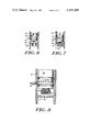
- FIG. 6 is a side elevational view in partial vertical cross section of a displacer disclosed herein.
- FIG. 7 is a side elevational view in partial vertical cross section of the displacer disclosed herein.
- FIG. 8 is a side elevational view in partial cross section showing an alternate embodiment of a phase shifting plug for use with the displacer.
- a cold finger assembly 10 including a housing 12 made of a material having a low thermal conductivity such as stainless steel. Disposed within the housing 12 is an abutment 14 which divides the interior of the housing 12 into two interior compartments 16 and 18.
- the compartment 16 has a substantially circular, cylindrical cross section.
- a displacer 20 is adapted for reciprocating longitudinal motion within the compartment 16.
- the displacer 20 is formed of a material such as nylon.
- the displacer 20 is hollow and contains a first bed of regenerative material 22 comprising, for example, copper screens or copper spheres.
- the displacer 20 also includes entrance ports 24 which can be seen more clearly with reference to FIGS. 6 and 7. Exit ports 26 are also provided in the upper end of the displacer 20.
- the displacer 20 has a length which is shorter than the length of the interior compartment 16 so that the displacer 20 creates within the interior compartment 16 a first (or primary) working volume 28 and a second (or secondary) working volume 30 in a working fluid to be described hereinafter.
- the working volume 28 effects a cooling to cryogenic temperatures of the cold end 32 of the housing 12.
- the cold end 32 may be made of a material having a very high thermal conductivity such as copper for more effective heat transfer from a thermal load (e.g. an infrared detector) in contact with the cold end 32.
- the plate 36 is preferably made of a material having high thermal conductivity such as copper.
- a series of longitudinally spaced-apart discs 38 are located between the plate 36 and the abutment 14 and are made of a material having a high thermal conductivity so as to serve as an effective heat exchanger.
- a first conduit 40 encircles the housing 12 adjacent to the second working volume 30 and communicates with the interior compartment 16 at its terminal end 42.
- a second conduit 44 communicates with the interior compartment 18.
- a compressor assembly 50 includes a structural housing 52 with a circular cylindrical cavity 54 therein.
- a piston assembly 56 includes longitudinally spaced-apart and mutually isolated pistons 58 and 60 which are rigidly connected to one another by connecting member 62.
- the connecting member 62 includes a slot 64 which engages a pin 66.
- the pin 66 is eccentrically mounted on a disc 68 driven by a motor 70. As the disc 68 rotates, the pin 66 follows the circular path indicated by the dotted circle 72. Thus, as the pin 66 traverses the circular path 72, the piston assembly 66 will reciprocate longitudinally within the cavity 54.
- the compressor assembly 50 disclosed herein is particularly well adapted for use with a cryogenic cooler. Because the pistons 58 and 60 are of the same diameter and mass, they are balanced about the drive point so that mechanical vibration is minimized. In addition, the "scotch yoke" design with its short moment arm and the linear motion of the piston assembly 56 result in low seal wear and hence long operating life. Furthermore, the prior art did not recognize the desirability or possibility of using a 180° opposed compressor in which the pistons were of the same size. This is the case because the prior art did not conceive of the phase-shifting arrangement disclosed herein which provides pneumatic cushioning for controllably decelerating the displacer so as to decrease slamming. This design results in a compressor which is very compact and one which is simple to fabricate.
- the working fluid in the conduit 44 enters the second interior compartment 18, passes through the second regenerative bed 34 past the plate 36 and the heat exchanger discs 38 and from there into interior compartment 16 through an opening 84 in the abutment 14 to create the working volume 30. Because of the seals 80 and 82, the working volumes 28 and 30 with their working fluid remain separated and isolated from one another.
- the pressure in working volume 28 is relatively high when the pressure in the working volume 30 is relatively lower and vice versa in a cyclical manner. Because of this cyclically varying pressure differential, the displacer 20 reciprocates within the first interior compartment 16. As is understood by those skilled in the thermodynamic art, as the displacer 20 reciprocates in a cyclical fashion, temperatures within both of the working volumes 28 and 30 decrease. That is, the energy expended results in cooling by the same means as in the well known thermodynamic stirling cycle.
- Cooling in both working volumes 28 and 30 is advantageous for two reasons.
- a significant aspect of the present invention is that the cold finger structure, in combination with the split phase pressure waves applied to the inlets provides for pneumatic cushioning of the displacer so that physical contact between the displacer and the cold end 32 and the abutment 14 is eliminated or controlled.
- An important factor producing this cushioning is the fluid flow impedances through the regenerative beds 22 and 34. That is, because of the nature of the flow paths, as the displacer rapidly approaches the end 32, for example, pressure builds up in the working volume 28 so as to slow and cushion the displacer before it comes into contact with the end 32. This effect is enhanced by the lateral location of the ports 26 unlike an end location as taught in the prior art. The lateral location also improves the heat transfer characteristics at the cold end 32.
- FIGS. 6 and 7 illustrate the important embodiment illustrated in FIGS. 6 and 7 enhance this pneumatic cushioning effect.
- a phase shifting plug 90 of a resiliant material is disposed on the lower surface of the displacer 20. As the displacer 20 moves downwardly, the plug 90 covers the opening 84 sealing off the working volume 30 thereby enhancing the transient pressure buildup so as to decelerate the displacer 20. By sealing the opening 84, the phase relationship of the pressures in the two working volumes has thus been shifted from the substantially 180° out-of-phase condition.
- FIG. 8 illustrates yet another embodiment adapted for providing enhanced pneumatic cushioning.
- a spring 92 is attached to the lower surface of the displacer 20 and covered by a metallic material 94. As with the embodiment of FIGS. 6 and 7, when the material 94 reaches the abutment 14, the opening 84 is sealed off so as to enhance the buildup of pressure. The spring 92 restores the covering to substantially the same position with each cycle.
- FIG. 2 Yet another embodiment of a cold finger assembly 100 adapted for operation with the compressor assembly 50 of FIG. 3 is shown in FIG. 2.
- a housing including sections 102 and 103 is separated into interior compartments 104 and 106 by a solid abutment 108.
- the displacer 110 is adapted for reciprocal movement within the interior compartment 104.
- the displacer 110 is hollow and filled with a bed of regenerative material such as small copper spheres.
- the annular region between the housing section 103 and the solid abutment 108 is also filled with a bed of regenerative material.
- a heat radiation shield 111 which surrounds the housing section 102 from the cold end 112 to a fluid inlet 114.
- the radiation shield 111 is made of a highly thermally conductive material such as copper and is effective in keeping radiant energy away from the cooled end 112.
- two working volumes 116 and 118 are created within the housing 102.
- longitudinally spaced-apart circular discs 120 are provided to enhance heat transfer.
- a second inlet 122 communicates with the interior compartment 106.
- the inlets 114 and 122 are connected to a compressor such as the compressor assembly 50 illustrated in FIG. 3. It will thus be appreciated that the displacer 110 will reciprocate in the internal compartment 104 under the influence of "push-pull" pressure waves from the compressor assembly 50. Such reciprocation causes cooling both in the primary working volume 116 and in the secondary working volume 118.
- thermally conductive masses 130 and 132 Disposed adjacent to the working volume 118 and in a heat exchange relation with the discs 120 are thermally conductive masses 130 and 132.
- a suitable material is copper.
- the cooling effect is transmitted through the thermally conductive material 130 and 132 so as to effect a precooling of the working fluid coming into the interior compartment 104 through the inlet 114.
- this arrangement not only effects a precooling of the working fluid but also substantially reduces the thermal gradient across the length of the displacer 110 which is effective to control unwanted thermophonics.
- the thermally conducting material 130 and 132 it is unnecessary that the inlet 113 be coiled around the outside of the assembly 100.
- a significant aspect of the embodiment of FIG. 2 is that as the displacer travels downwardly, it sequentially comes abreast of the discs 120. Because of the close tolerance between these discs and the displacer 110, the fluid flow path is progressively reduced as each of the discs is encountered. When the displacer reaches the lowermost disc, the flow is completely cut off. This progressive diminution of flow thus provides for the controlled deceleration of the displacer by way of pneumatic cushioning. In this way, slamming is effectively controlled by this phase shifting means.
Landscapes
- Engineering & Computer Science (AREA)
- Physics & Mathematics (AREA)
- Mechanical Engineering (AREA)
- Thermal Sciences (AREA)
- General Engineering & Computer Science (AREA)
- Compressors, Vaccum Pumps And Other Relevant Systems (AREA)
- Compressor (AREA)
Priority Applications (11)
| Application Number | Priority Date | Filing Date | Title |
|---|---|---|---|
| US06/358,626 US4385499A (en) | 1982-03-16 | 1982-03-16 | Miniature cryogenic cooling system with split-phase dual compressor and phase-shifting device |
| DE19833337017 DE3337017T1 (de) | 1982-03-16 | 1983-03-11 | Miniatur-Tiefsttemperaturkühlsystem mit Spaltphasendoppelkompressor und Phasenverschiebungsvorrichtung |
| JP58501502A JPS59500426A (ja) | 1982-03-16 | 1983-03-11 | 分相した2個のコンプレッサおよび移相装置を有する小型極低温冷却装置 |
| PCT/US1983/000322 WO1983003296A1 (fr) | 1982-03-16 | 1983-03-11 | Systeme cryogenique miniature de refroidissement comprenant un compresseur double a phase separee et un dispositif de decalage de phase |
| GB08330115A GB2129921B (en) | 1982-03-16 | 1983-03-11 | Miniature cryogenic cooling system with split-phase dual compressor and phase-shifting device |
| EP83901456A EP0103634A1 (fr) | 1982-03-16 | 1983-03-11 | Systeme cryogenique miniature de refroidissement comprenant un compresseur double a phase separee et un dispositif de decalage de phase |
| FR8304259A FR2523699B1 (fr) | 1982-03-16 | 1983-03-15 | Appareil miniature de refroidissement cryogenique, notamment pour capteurs infrarouges |
| IL68128A IL68128A0 (en) | 1982-03-16 | 1983-03-15 | Miniature cryogenic cooling system with split phase dual compression and phase shifting device |
| IT67293/83A IT1158903B (it) | 1982-03-16 | 1983-03-16 | Sistema di raffreddamento criogenico miniaturizzato |
| IT8353064U IT8353064V0 (it) | 1982-03-16 | 1983-03-16 | Sistema di raffreddamento criogeni co miniaturizzato |
| US06/498,866 US4479358A (en) | 1982-03-16 | 1983-05-27 | Miniature cryogenic cooling system with split-phase dual compressor and phase-shifting device |
Applications Claiming Priority (1)
| Application Number | Priority Date | Filing Date | Title |
|---|---|---|---|
| US06/358,626 US4385499A (en) | 1982-03-16 | 1982-03-16 | Miniature cryogenic cooling system with split-phase dual compressor and phase-shifting device |
Related Child Applications (1)
| Application Number | Title | Priority Date | Filing Date |
|---|---|---|---|
| US06/498,866 Continuation-In-Part US4479358A (en) | 1982-03-16 | 1983-05-27 | Miniature cryogenic cooling system with split-phase dual compressor and phase-shifting device |
Publications (1)
| Publication Number | Publication Date |
|---|---|
| US4385499A true US4385499A (en) | 1983-05-31 |
Family
ID=23410412
Family Applications (1)
| Application Number | Title | Priority Date | Filing Date |
|---|---|---|---|
| US06/358,626 Expired - Fee Related US4385499A (en) | 1982-03-16 | 1982-03-16 | Miniature cryogenic cooling system with split-phase dual compressor and phase-shifting device |
Country Status (9)
| Country | Link |
|---|---|
| US (1) | US4385499A (fr) |
| EP (1) | EP0103634A1 (fr) |
| JP (1) | JPS59500426A (fr) |
| DE (1) | DE3337017T1 (fr) |
| FR (1) | FR2523699B1 (fr) |
| GB (1) | GB2129921B (fr) |
| IL (1) | IL68128A0 (fr) |
| IT (2) | IT8353064V0 (fr) |
| WO (1) | WO1983003296A1 (fr) |
Cited By (4)
| Publication number | Priority date | Publication date | Assignee | Title |
|---|---|---|---|---|
| US6065295A (en) * | 1995-12-15 | 2000-05-23 | Leybold Vakuum Gmbh | Low-temperature refrigerator with cold head and a process for optimizing said cold head for a desired temperature range |
| US6176088B1 (en) * | 1998-01-22 | 2001-01-23 | Edax, Inc. | Method and devices to reduce vibrations in a cryostat |
| US20060201163A1 (en) * | 2003-04-24 | 2006-09-14 | Hans-Ulrich Haefner | Heat-storing medium |
| US11209192B2 (en) * | 2019-07-29 | 2021-12-28 | Cryo Tech Ltd. | Cryogenic Stirling refrigerator with a pneumatic expander |
Families Citing this family (1)
| Publication number | Priority date | Publication date | Assignee | Title |
|---|---|---|---|---|
| US5711157A (en) * | 1995-05-16 | 1998-01-27 | Kabushiki Kaisha Toshiba | Cooling system having a plurality of cooling stages in which refrigerant-filled chamber type refrigerators are used |
Citations (5)
| Publication number | Priority date | Publication date | Assignee | Title |
|---|---|---|---|---|
| US3523427A (en) * | 1968-12-23 | 1970-08-11 | Garrett Corp | Gas engine-refrigerator |
| US4078389A (en) * | 1976-04-30 | 1978-03-14 | Cryogenic Technology, Inc. | Lost-motion refrigeration drive system |
| US4090859A (en) * | 1977-03-23 | 1978-05-23 | The United States Of America As Represented By The Secretary Of The Army | Dual-displacer two-stage split cycle cooler |
| US4092833A (en) * | 1977-02-28 | 1978-06-06 | The United States Of America As Represented By The Secretary Of The Army | Split-phase cooler with expansion piston motion enhancer |
| US4206609A (en) * | 1978-09-01 | 1980-06-10 | Actus, Inc. | Cryogenic surgical apparatus and method |
Family Cites Families (6)
| Publication number | Priority date | Publication date | Assignee | Title |
|---|---|---|---|---|
| US3148512A (en) * | 1963-05-15 | 1964-09-15 | Little Inc A | Refrigeration apparatus |
| US3188818A (en) * | 1963-11-12 | 1965-06-15 | Little Inc A | Refrigeration method and apparatus embodying fluid expansion |
| US3552120A (en) * | 1969-03-05 | 1971-01-05 | Research Corp | Stirling cycle type thermal device |
| US3851173A (en) * | 1973-06-25 | 1974-11-26 | Texas Instruments Inc | Thermal energy receiver |
| US4092829A (en) * | 1975-11-06 | 1978-06-06 | The United States Of America As Represented By The Secretary Of The Army | Balanced compressor |
| US4259844A (en) * | 1979-07-30 | 1981-04-07 | Helix Technology Corporation | Stacked disc heat exchanger for refrigerator cold finger |
-
1982
- 1982-03-16 US US06/358,626 patent/US4385499A/en not_active Expired - Fee Related
-
1983
- 1983-03-11 WO PCT/US1983/000322 patent/WO1983003296A1/fr active Application Filing
- 1983-03-11 JP JP58501502A patent/JPS59500426A/ja active Pending
- 1983-03-11 DE DE19833337017 patent/DE3337017T1/de not_active Withdrawn
- 1983-03-11 EP EP83901456A patent/EP0103634A1/fr not_active Withdrawn
- 1983-03-11 GB GB08330115A patent/GB2129921B/en not_active Expired
- 1983-03-15 IL IL68128A patent/IL68128A0/xx unknown
- 1983-03-15 FR FR8304259A patent/FR2523699B1/fr not_active Expired
- 1983-03-16 IT IT8353064U patent/IT8353064V0/it unknown
- 1983-03-16 IT IT67293/83A patent/IT1158903B/it active
Patent Citations (5)
| Publication number | Priority date | Publication date | Assignee | Title |
|---|---|---|---|---|
| US3523427A (en) * | 1968-12-23 | 1970-08-11 | Garrett Corp | Gas engine-refrigerator |
| US4078389A (en) * | 1976-04-30 | 1978-03-14 | Cryogenic Technology, Inc. | Lost-motion refrigeration drive system |
| US4092833A (en) * | 1977-02-28 | 1978-06-06 | The United States Of America As Represented By The Secretary Of The Army | Split-phase cooler with expansion piston motion enhancer |
| US4090859A (en) * | 1977-03-23 | 1978-05-23 | The United States Of America As Represented By The Secretary Of The Army | Dual-displacer two-stage split cycle cooler |
| US4206609A (en) * | 1978-09-01 | 1980-06-10 | Actus, Inc. | Cryogenic surgical apparatus and method |
Cited By (4)
| Publication number | Priority date | Publication date | Assignee | Title |
|---|---|---|---|---|
| US6065295A (en) * | 1995-12-15 | 2000-05-23 | Leybold Vakuum Gmbh | Low-temperature refrigerator with cold head and a process for optimizing said cold head for a desired temperature range |
| US6176088B1 (en) * | 1998-01-22 | 2001-01-23 | Edax, Inc. | Method and devices to reduce vibrations in a cryostat |
| US20060201163A1 (en) * | 2003-04-24 | 2006-09-14 | Hans-Ulrich Haefner | Heat-storing medium |
| US11209192B2 (en) * | 2019-07-29 | 2021-12-28 | Cryo Tech Ltd. | Cryogenic Stirling refrigerator with a pneumatic expander |
Also Published As
| Publication number | Publication date |
|---|---|
| DE3337017T1 (de) | 1984-11-29 |
| EP0103634A1 (fr) | 1984-03-28 |
| GB2129921A (en) | 1984-05-23 |
| GB8330115D0 (en) | 1983-12-21 |
| IT8353064V0 (it) | 1983-03-16 |
| GB2129921B (en) | 1985-08-14 |
| WO1983003296A1 (fr) | 1983-09-29 |
| JPS59500426A (ja) | 1984-03-15 |
| IL68128A0 (en) | 1983-06-15 |
| IT8367293A0 (it) | 1983-03-16 |
| FR2523699A1 (fr) | 1983-09-23 |
| IT1158903B (it) | 1987-02-25 |
| FR2523699B1 (fr) | 1987-04-30 |
Similar Documents
| Publication | Publication Date | Title |
|---|---|---|
| EP1158256B1 (fr) | Appareil frigorifique cryogénique à tube de pulsation comportant un volume tampon intégré | |
| US5269147A (en) | Pulse tube refrigerating system | |
| US4425764A (en) | Micro-cryogenic system with pseudo two stage cold finger, stationary regenerative material, and pre-cooling of the working fluid | |
| US6427450B1 (en) | Cryocooler motor with split return iron | |
| US5904046A (en) | Pulse tube refrigerating system | |
| US3774405A (en) | Magnetically driven cryogen vuilleumier refrigerator | |
| US5791149A (en) | Orifice pulse tube refrigerator with pulse tube flow separator | |
| US4862695A (en) | Split sterling cryogenic cooler | |
| US4385499A (en) | Miniature cryogenic cooling system with split-phase dual compressor and phase-shifting device | |
| US4479358A (en) | Miniature cryogenic cooling system with split-phase dual compressor and phase-shifting device | |
| JPH0781754B2 (ja) | 冷凍機 | |
| US5251448A (en) | Heat machine | |
| US4277947A (en) | Cryogenic cooler having telescoping multistage regenerator-displacers | |
| EP0311726A2 (fr) | Réfrigérateur cryogénique | |
| GB2073861A (en) | Refrigerating system | |
| US6041599A (en) | Thermal power machine having a moving regenerator | |
| US3765187A (en) | Pneumatic stirling cycle cooler with non-contaminating compressor | |
| EP0335643B1 (fr) | Machine frigorifique à gaz | |
| US5406801A (en) | Thermally operated refrigerator | |
| US4090858A (en) | Two-stage split-cycle cooler with pneumatic piston | |
| US4253859A (en) | Gas refrigerator | |
| US3849652A (en) | Floating annulus for gas porting to a moving heat exchanger | |
| Haarhuis | The mc 80-a magnetically driven Stirling refrigerator | |
| CA1190757A (fr) | Systeme cryogenique miniature a compresseur double biphase et dispositif echangeur de phases | |
| CN219199535U (zh) | 斯特林制冷机 |
Legal Events
| Date | Code | Title | Description |
|---|---|---|---|
| AS | Assignment |
Owner name: KRYOVAC SCIENTIFIC CORPORATION, COLUMBIA DRIVE, BL Free format text: ASSIGNMENT OF ASSIGNORS INTEREST.;ASSIGNOR:LAM, CALVIN K.;REEL/FRAME:004102/0856 Effective date: 19830308 |
|
| MAFP | Maintenance fee payment |
Free format text: PAYMENT OF MAINTENANCE FEE, 4TH YEAR, PL 96-517 (ORIGINAL EVENT CODE: M170); ENTITY STATUS OF PATENT OWNER: SMALL ENTITY Year of fee payment: 4 |
|
| FEPP | Fee payment procedure |
Free format text: PAYOR NUMBER ASSIGNED (ORIGINAL EVENT CODE: ASPN); ENTITY STATUS OF PATENT OWNER: SMALL ENTITY |
|
| FEPP | Fee payment procedure |
Free format text: MAINTENANCE FEE REMINDER MAILED (ORIGINAL EVENT CODE: REM.); ENTITY STATUS OF PATENT OWNER: SMALL ENTITY |
|
| LAPS | Lapse for failure to pay maintenance fees | ||
| STCH | Information on status: patent discontinuation |
Free format text: PATENT EXPIRED DUE TO NONPAYMENT OF MAINTENANCE FEES UNDER 37 CFR 1.362 |
|
| FP | Lapsed due to failure to pay maintenance fee |
Effective date: 19910602 |