US4385276A - Mounting of semiconductor sensing means for an electromagnetic tachometer in a portable electric tool - Google Patents
Mounting of semiconductor sensing means for an electromagnetic tachometer in a portable electric tool Download PDFInfo
- Publication number
- US4385276A US4385276A US06/314,983 US31498381A US4385276A US 4385276 A US4385276 A US 4385276A US 31498381 A US31498381 A US 31498381A US 4385276 A US4385276 A US 4385276A
- Authority
- US
- United States
- Prior art keywords
- annular portion
- rotor
- ring member
- bridge
- carried
- Prior art date
- Legal status (The legal status is an assumption and is not a legal conclusion. Google has not performed a legal analysis and makes no representation as to the accuracy of the status listed.)
- Expired - Lifetime
Links
- 239000004065 semiconductor Substances 0.000 title claims abstract description 20
- 238000001816 cooling Methods 0.000 claims abstract description 19
- 241000239290 Araneae Species 0.000 claims abstract description 16
- 230000000717 retained effect Effects 0.000 claims abstract description 13
- 239000002991 molded plastic Substances 0.000 claims description 3
- 230000005355 Hall effect Effects 0.000 abstract description 5
- 239000000463 material Substances 0.000 description 5
- 239000004033 plastic Substances 0.000 description 5
- 230000002411 adverse Effects 0.000 description 3
- 238000009413 insulation Methods 0.000 description 3
- 241000321728 Tritogonia verrucosa Species 0.000 description 2
- 238000004519 manufacturing process Methods 0.000 description 2
- 230000002860 competitive effect Effects 0.000 description 1
- 230000008878 coupling Effects 0.000 description 1
- 238000010168 coupling process Methods 0.000 description 1
- 238000005859 coupling reaction Methods 0.000 description 1
- 230000003247 decreasing effect Effects 0.000 description 1
- 230000001419 dependent effect Effects 0.000 description 1
- 238000012986 modification Methods 0.000 description 1
- 230000004048 modification Effects 0.000 description 1
- 230000000737 periodic effect Effects 0.000 description 1
Images


Classifications
-
- H—ELECTRICITY
- H02—GENERATION; CONVERSION OR DISTRIBUTION OF ELECTRIC POWER
- H02K—DYNAMO-ELECTRIC MACHINES
- H02K23/00—DC commutator motors or generators having mechanical commutator; Universal AC/DC commutator motors
- H02K23/66—Structural association with auxiliary electric devices influencing the characteristic of, or controlling, the machine, e.g. with impedances or switches
-
- G—PHYSICS
- G01—MEASURING; TESTING
- G01P—MEASURING LINEAR OR ANGULAR SPEED, ACCELERATION, DECELERATION, OR SHOCK; INDICATING PRESENCE, ABSENCE, OR DIRECTION, OF MOVEMENT
- G01P3/00—Measuring linear or angular speed; Measuring differences of linear or angular speeds
- G01P3/42—Devices characterised by the use of electric or magnetic means
- G01P3/44—Devices characterised by the use of electric or magnetic means for measuring angular speed
- G01P3/48—Devices characterised by the use of electric or magnetic means for measuring angular speed by measuring frequency of generated current or voltage
- G01P3/481—Devices characterised by the use of electric or magnetic means for measuring angular speed by measuring frequency of generated current or voltage of pulse signals
- G01P3/487—Devices characterised by the use of electric or magnetic means for measuring angular speed by measuring frequency of generated current or voltage of pulse signals delivered by rotating magnets
-
- H—ELECTRICITY
- H02—GENERATION; CONVERSION OR DISTRIBUTION OF ELECTRIC POWER
- H02K—DYNAMO-ELECTRIC MACHINES
- H02K11/00—Structural association of dynamo-electric machines with electric components or with devices for shielding, monitoring or protection
- H02K11/20—Structural association of dynamo-electric machines with electric components or with devices for shielding, monitoring or protection for measuring, monitoring, testing, protecting or switching
- H02K11/21—Devices for sensing speed or position, or actuated thereby
- H02K11/215—Magnetic effect devices, e.g. Hall-effect or magneto-resistive elements
-
- H—ELECTRICITY
- H02—GENERATION; CONVERSION OR DISTRIBUTION OF ELECTRIC POWER
- H02K—DYNAMO-ELECTRIC MACHINES
- H02K11/00—Structural association of dynamo-electric machines with electric components or with devices for shielding, monitoring or protection
- H02K11/30—Structural association with control circuits or drive circuits
- H02K11/33—Drive circuits, e.g. power electronics
-
- H—ELECTRICITY
- H02—GENERATION; CONVERSION OR DISTRIBUTION OF ELECTRIC POWER
- H02K—DYNAMO-ELECTRIC MACHINES
- H02K7/00—Arrangements for handling mechanical energy structurally associated with dynamo-electric machines, e.g. structural association with mechanical driving motors or auxiliary dynamo-electric machines
- H02K7/14—Structural association with mechanical loads, e.g. with hand-held machine tools or fans
- H02K7/145—Hand-held machine tool
Definitions
- the control system may be intended for speed control; or for electronic or so-called "brushless" commutation; or in the case of a stepping motor, position sensing and control.
- a signal generating or pick-up sensing means is usually employed.
- the sensing means may comprise a permanent magnet carried by the shaft and cooperating with one or more semiconductor sensing devices, such as a Hall-Effect generator, fixed with respect to the circular orbit of the rotating magnet.
- the magnet triggers the Hall-Effect generator to obtain the desired feedback signal, and the signal in turn is fed to suitable electronic circuitry for purposes of controlling a desired function of the motor.
- suitable electronic circuitry for purposes of controlling a desired function of the motor.
- the portable electric tool includes a field case having a rearward bridge portion provided with a bearing for journaling an armature shaft therein.
- a ring member is piloted on the bridge and has an annular portion extending rearwardly therefrom.
- a counterbalanced rotor is mounted on the armature shaft, rearwardly of the bridge, and is nested within the annular portion of the ring.
- a permanent magnet is carried by the rotor and cooperates with a semiconductor sensing device mounted on the ring.
- An end cap is secured to the field case and has a portion engaging the annular portion of the ring, thereby securing the ring against the bridge on the field case.
- a fan carried by the armature shaft draws cooling air in through ventilating openings in the end cap.
- the majority of the cooling air is confined by the annular portion of the ring, experiences a turbulence created by the rotor, and is arranged to flow into the field case to cool the bearing and other components of the motor.
- the annular portion of the ring has an external boss with a notch formed therein substantially tangential to the annular portion.
- a printed circuit board is received in the notch and is resiliently loaded, thereby alleviating vibratory forces, and the semiconductor sensing device is mounted on the board.
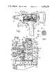
- FIG. 1 is a side elevation of a portable electric tool within which the teachings of the present invention may find more particular utility, parts being broken away and sectioned to show certain components of the motor and the overall mounting means for the semiconductor sensing means;
- FIG. 2 is an enlarged longitudinal section of a portion of FIG. 1, showing a preferred embodiment of the mounting means
- FIG. 3 is a section view, taken along the lines 3--3 of FIG. 2, showing the armature shaft journaled in a bearing nested within a spider member retained in the rearward bridge portion of the motor field case;
- FIG. 4 is an exploded elevation showing a portion of the bridge, an extension shaft secured to the armature shaft and projecting rearwardly therefrom, a rotor carried by the extension shaft (the rotor being displaced 180 degrees from its position shown in FIG. 2), and a ring member piloted on the bridge of the field case and enclosing the rotor;
- FIG. 5 is a view, taken along the lines 5--5 of FIG. 4, showing (in plan view) the spider member, the annular portion of the bridge for piloting the ring, the adjacent flat surface of the bridge, and a pair of diametrically-opposed longitudinal slots formed in the bridge for receiving respective brushholders therein;
- FIG. 6 is a section view, taken along the lines 6--6 of FIG. 4, and showing the flat surfaces formed on the extension shaft for keying the rotor thereto;
- FIG. 7 is a view, taken along the lines 7--7 of FIG. 4, showing the counterbalanced rotor, and further showing the means for retaining a permanent magnet therein;
- FIG. 8 is a view, taken along the lines 8--8 of FIG. 4, showing the crushable projections on the inner periphery of the ring, the projections cooperating with the annular portion of the bridge for thereby piloting the ring on the field case;
- FIG. 9 is a view, taken along the lines 9--9 of FIG. 4, showing the external boss on the annular portion of the ring, the boss having a notch formed therein substantially tangential to the annular portion of the ring;
- FIG. 10 corresponds to a portion of FIG. 9, but shows a printed circuit board received in the notch, the board carrying a semiconductor sensing device;
- FIG. 11 is a side elevation of the printed circuit board and semiconductor device
- FIG. 12 is a top plan view thereof
- FIG. 13 is a top plan view of an alternate embodiment of the rotor, showing a pair of magnets mounted in respective recesses therein;
- FIG. 14 is a section view, taken across the lines 14--14 of FIG. 13.
- FIG. 1 there is illustrated a portable electric drill 10 with which the teachings of the present invention may find more particular utility. It will be appreciated by those skilled in the art that the teachings of the present invention are not confined to the particular drill 10, but rather are equally applicable to a wide variety of portable electric tools, appliances, and other products having similar design criteria and operating parameters.
- the drill 10 comprises a main motor housing 11, an end cap housing 12 secured rearwardly thereof, a gear case 13 secured forward thereof, a chuck 14 for retaining a drill bit (not shown), an end handle 15 secured rearwardly of the end cap housing, and an auxiliary handle 16.
- the motor housing and end cap housing are joined together along a common vertical plane and have respective depending portions joined together to form a pistol-grip handle 17.
- the pistol grip handle encloses a main switch (not shown) which is controlled by means of a trigger 18 projecting forwardly of the pistol-grip handle.
- the motor housing forms a compartment for a motor, designated generally as at 19.
- the motor includes a field case (not shown for ease of illustration) and further includes an armature 20 having a shaft 21.
- the armature shaft has a forward portion 22 journaled in a first bearing 23 retained in the gear case.
- a fan 24 is mounted on the armature shaft adjacent to the bearing, for cooling purposes.
- the motor housing, end cap housing, and end handle are molded from a suitable plastic material.
- the speed of the drill is maintained by electronic circuit means, including a microprocessor 25, housed above the motor.
- the microprocessor cooperates with a speed-selecting switch 26; and the switch is connected to a manually-operable selector knob 27, which is recessed within a boss 28 formed between the cooperating housings.
- the electronic circuit means is responsive to a feedback signal which is a function of the speed of rotation of the armature shaft. This feedback signal is generated by a tachometer or tacho-generator, generally designated at 29, which comprises the semiconductor sensing means.
- the wired connections between the tacho-generator and the microprocessor, as well as the particular electronic circuitry, form no part of the present invention and hence have been omitted for ease of illustration.
- the motor housing includes a field case 30 which is preferably molded from a suitable plastic material.
- the field case has an integrally-formed rearward bridge portion 31.
- the bridge has a spider member 32 integrally molded therein (forming a heat sink) and the spider has a toothed periphery defining a number of circumferentially-spaced openings 33, as shown more clearly in FIG. 5.
- a sleeve bearing 34 is nested concentrically within the spider, and press-fitted therein, for journaling the rearward portion 35 of the armature shaft. As shown more clearly in FIG.
- a pair of diametrically-opposed longitudinal slots 36 are formed in the bridge of the field case, and respective brushholders (one of which is shown as at 37) are retained in the slots.
- the brushholders have brushes (one of which is shown as at 38) for engaging a commutator 39 mounted on the armature shaft.
- the bridge of the field case, as well as the brushholders have been shown in a vertical orientation for ease of illustration; however, it will be appreciated by those skilled in the art that, if desired, the brushholders (and the brushes therein) could be circumferentially displaced or offset from the vertical axis.
- a ring member 40 (which is preferably molded from a suitable plastic material) has an inner circumference provided with a series of circumferentially-spaced crushable projections 41, which engage a rearwardly-projecting annular portion 42 (shown in FIGS. 4 and 5) formed on the bridge of the field case.
- the ring is thus piloted on the annular portion of the bridge and is retained thereon, flush against the adjacent flat surface 43 of the bridge as shown in FIG. 2.
- the ring has a rearwardly-extending annular portion 44; and the end cap carries a pair of rubber plugs (one of which is shown as at 45 in FIG. 2) for engaging the annular portion of the ring.
- the ring may be quickly and easily assembled within the housing and is rigidly retained therein, between the end cap and the bridge of the field case.
- an extension shaft 46 is threadably received within a blind axial bore 47 formed in the rearward portion of the armature shaft.
- the extension shaft projects rearwardly of the bridge, and a counterbalanced rotor 48 is mounted thereon.
- the rotor which is preferably molded from a suitable plastic material, is nested within the annular portion of the ring.
- the shaft has a pair of parallel flats 49 (shown in FIG. 6) for cooperation with an internal keyway 50 formed in the rotor (shown in FIG. 7) thereby coupling the rotor to the shaft.
- the rotor has a recess 51 formed therein for receiving a permanent magnet 52.
- a pair of studs 53 are integrally formed in the rotor, one on each side of the recess. When the magnet is received in the recess, the studs are deformed to thereby retain the magnet in its recess in the rotor.
- the rotor also has an enlarged counterbalance portion 48a to preclude any undesired dynamic unbalance.
- the annular portion of the ring has an external boss 54, and the boss has a rectangular notch 55 formed therein substantially tangential to the annular portion of the ring (as shown in FIG. 9).
- a printed circuit board 56 (shown in FIGS. 11 and 12) is received within the notch (as shown in FIG. 10) and carries a semiconductor sensing device 57.
- the sensing device may comprise a Hall-Effect generator which is responsive to the presence of a magnetic field. The sensing device thereby cooperates with the permanent magnet carried by the rotor and generates a series of control signals dependent upon the motor speed (as understood by those skilled in the art) for input to the electronic speed-control means.
- FIG. 9 the annular portion of the ring has an external boss 54, and the boss has a rectangular notch 55 formed therein substantially tangential to the annular portion of the ring (as shown in FIG. 9).
- a printed circuit board 56 (shown in FIGS. 11 and 12) is received within the notch (
- the printed circuit board has a number of connecting wires, one of which is shown as at 58; and because of the tangentially-displaced position of the board, the wires are confined by the annular portion of the ring, thereby precluding the wires from becoming entangled with the rotor or armature shaft.
- a rubber plug 59 is received within a cylindrical recess 60 formed in the boss and communicating with the notch therein. The plug bears against the printed circuit board, thereby resiliently loading the board and alleviating any adverse vibratory forces experienced during operation of the tool.
- the end cap has a plurality of slotted openings 61 formed therein.
- the fan 24 draws cooling air in through the openings in the end cap, as shown by the small arrows.
- the majority of the cooling air is confined by the annular portion of the ring, experiences a turbulence due to the rotation of the rotor within the annular portion, and flows through the circumferentially-spaced openings in the spider for purposes of cooling the bearing for the rearward portion of the armature shaft. Thereafter, the cooling air continues through the motor compartment.
- the ring is also provided with two pairs of prongs 62 formed integrally therewith.
- the prongs extend forwardly of the tool, within the respective slots 36 in the bridge portion of the field case, and terminate just short of the brushholders 37 as shown in FIG. 2. As a result, the prongs maintain the proper electrical spacing, should the brushholders ever become loose, thereby assisting in maintaining the requirements of double insulation.
- the rotor 63 is preferably molded from a suitable plastic material and has a pair of recesses 64 and 65 for receiving permanent magnets 66 and 67, respectively.
- the magnets are retained in the recesses by means of deformed studs, as at 68, which are similar to the studs 53 on the rotor 48 of the FIG. 2 embodiment.
- the rotor 63 is thus counterbalanced, and respective through slots 69 are formed therein for reducing its weight.
- the semiconductor sensing means and its mounting means achieve the objectives of simplicity, low cost, ease of assembly, rigidity, and reliability of operation.
- the present invention is ideally suited for application to a portable electric tool having an electronic speed-control or other control system.
- a maximum number of functions are achieved with a minimum number of components.
- the radial tolerances may be economically-controlled to close limits; and conversely, the axial tolerances or axial "stack up", which are relatively large and usually difficult to control economically, are relatively inconsequential and do not interfere with the proper triggering of the Hall-Effect generator under the periodic influence of the rotating magnet.
Landscapes
- Engineering & Computer Science (AREA)
- Power Engineering (AREA)
- Microelectronics & Electronic Packaging (AREA)
- Physics & Mathematics (AREA)
- General Physics & Mathematics (AREA)
Abstract
Description
Claims (8)
Priority Applications (1)
| Application Number | Priority Date | Filing Date | Title |
|---|---|---|---|
| US06/314,983 US4385276A (en) | 1980-01-28 | 1981-10-26 | Mounting of semiconductor sensing means for an electromagnetic tachometer in a portable electric tool |
Applications Claiming Priority (2)
| Application Number | Priority Date | Filing Date | Title |
|---|---|---|---|
| US11625980A | 1980-01-28 | 1980-01-28 | |
| US06/314,983 US4385276A (en) | 1980-01-28 | 1981-10-26 | Mounting of semiconductor sensing means for an electromagnetic tachometer in a portable electric tool |
Related Parent Applications (1)
| Application Number | Title | Priority Date | Filing Date |
|---|---|---|---|
| US11625980A Continuation-In-Part | 1980-01-28 | 1980-01-28 |
Publications (1)
| Publication Number | Publication Date |
|---|---|
| US4385276A true US4385276A (en) | 1983-05-24 |
Family
ID=26814054
Family Applications (1)
| Application Number | Title | Priority Date | Filing Date |
|---|---|---|---|
| US06/314,983 Expired - Lifetime US4385276A (en) | 1980-01-28 | 1981-10-26 | Mounting of semiconductor sensing means for an electromagnetic tachometer in a portable electric tool |
Country Status (1)
| Country | Link |
|---|---|
| US (1) | US4385276A (en) |
Cited By (23)
| Publication number | Priority date | Publication date | Assignee | Title |
|---|---|---|---|---|
| US4503391A (en) * | 1982-03-11 | 1985-03-05 | Robert Bosch Gmbh | Rotary angular position sensor with magnet and pole disk assembly mounted on rotatable shaft |
| FR2568377A1 (en) * | 1984-07-25 | 1986-01-31 | Jouan | Hall-effect speed sensor built into a rotating machine. |
| EP0175992A1 (en) * | 1984-09-19 | 1986-04-02 | Siemens Aktiengesellschaft | Process for the Manufacture of a support for the Brushes of a Commutator Machine |
| EP0235443A1 (en) * | 1985-10-31 | 1987-09-09 | Black & Decker Inc. | Improvements in or relating to electric motors and components therefor |
| US4703262A (en) * | 1984-04-26 | 1987-10-27 | Fanuc Ltd | Mounting structure for spindle orientation magnetic sensor system |
| US4773829A (en) * | 1986-09-10 | 1988-09-27 | Etudes Techniques Et Representations Industrielles E.T.R.I. | Centrifugal fan driven by an electronic-commutation direct-current motor |
| US5053664A (en) * | 1989-01-18 | 1991-10-01 | Aisan Kogyo Kabushiki Kaisha | Motor-driven fuel pump |
| US5099160A (en) * | 1988-07-16 | 1992-03-24 | Robert Bosch Gmbh | Powered hand tool having an enclosed-ventilated drive motor |
| US5119466A (en) * | 1989-05-24 | 1992-06-02 | Asmo Co., Ltd. | Control motor integrated with a direct current motor and a speed control circuit |
| US5443196A (en) * | 1991-12-11 | 1995-08-22 | Illinois Tool Works, Inc. | Fastener applicator |
| US5522268A (en) * | 1993-04-07 | 1996-06-04 | Klaus Kobold | Turbine hub including pulse-generating elements sealing disposed within a two part molded container |
| DE19617134A1 (en) * | 1996-04-29 | 1997-10-30 | Siemens Ag | Brushless electric motor control magnet |
| WO1998040751A1 (en) * | 1997-03-12 | 1998-09-17 | Robert Bosch Gmbh | Motor with speed of rotation detected by a hall sensor |
| FR2765744A1 (en) * | 1997-07-02 | 1999-01-08 | Rockwell Lvs | ACTIVATION MOTOR FOR EXAMPLE OF A MOTOR VEHICLE FUNCTIONAL MEMBER |
| US6043575A (en) * | 1999-03-05 | 2000-03-28 | Snap-On Tools Company | Power tool with air deflector for venting motor exhaust air |
| US6070506A (en) * | 1998-07-20 | 2000-06-06 | Snap-On Tools Company | Ratchet head electronic torque wrench |
| US20080150375A1 (en) * | 2005-07-26 | 2008-06-26 | Jefcom Co., Ltd. | Electric power tool |
| US8272813B1 (en) * | 2006-01-30 | 2012-09-25 | Wise Robert W | Combination power tool and object sensor |
| WO2013022390A1 (en) * | 2011-08-08 | 2013-02-14 | Husqvarna Ab | A magnet holder for use in a throttle position sensor, a magnet holder for use in an angular position sensor, and methods for manufacturing them |
| CN103713149A (en) * | 2012-09-29 | 2014-04-09 | 博世电动工具(中国)有限公司 | Speed measuring device |
| US20170136614A1 (en) * | 2014-06-30 | 2017-05-18 | Hitachi Koki Co., Ltd. | Electric tool |
| CN109391059A (en) * | 2018-10-26 | 2019-02-26 | 湖南航天磁电有限责任公司 | A kind of high-power electric tool brushless motor system |
| US20190061117A1 (en) * | 2017-08-29 | 2019-02-28 | Panasonic Intellectual Property Management Co., Ltd. | Electric power tool |
Citations (3)
| Publication number | Priority date | Publication date | Assignee | Title |
|---|---|---|---|---|
| DE2539548A1 (en) * | 1974-09-20 | 1976-07-29 | Ford Werke Ag | MAGNETICALLY ACTIVATED ELECTRIC SIGNAL GENERATOR |
| JPS5254469A (en) * | 1975-10-28 | 1977-05-02 | Omron Tateisi Electronics Co | Revolution pulse generating device |
| JPS54113374A (en) * | 1978-02-24 | 1979-09-04 | Victor Co Of Japan Ltd | Rotation detector |
-
1981
- 1981-10-26 US US06/314,983 patent/US4385276A/en not_active Expired - Lifetime
Patent Citations (3)
| Publication number | Priority date | Publication date | Assignee | Title |
|---|---|---|---|---|
| DE2539548A1 (en) * | 1974-09-20 | 1976-07-29 | Ford Werke Ag | MAGNETICALLY ACTIVATED ELECTRIC SIGNAL GENERATOR |
| JPS5254469A (en) * | 1975-10-28 | 1977-05-02 | Omron Tateisi Electronics Co | Revolution pulse generating device |
| JPS54113374A (en) * | 1978-02-24 | 1979-09-04 | Victor Co Of Japan Ltd | Rotation detector |
Non-Patent Citations (1)
| Title |
|---|
| Wehmer, "Electromagnetic Tachometer", Dec. 1968, pp. 746-747, IBM Technical Disclosure Bulletin, vol. 11, No. 7. * |
Cited By (33)
| Publication number | Priority date | Publication date | Assignee | Title |
|---|---|---|---|---|
| US4503391A (en) * | 1982-03-11 | 1985-03-05 | Robert Bosch Gmbh | Rotary angular position sensor with magnet and pole disk assembly mounted on rotatable shaft |
| US4703262A (en) * | 1984-04-26 | 1987-10-27 | Fanuc Ltd | Mounting structure for spindle orientation magnetic sensor system |
| FR2568377A1 (en) * | 1984-07-25 | 1986-01-31 | Jouan | Hall-effect speed sensor built into a rotating machine. |
| EP0175992A1 (en) * | 1984-09-19 | 1986-04-02 | Siemens Aktiengesellschaft | Process for the Manufacture of a support for the Brushes of a Commutator Machine |
| EP0235443A1 (en) * | 1985-10-31 | 1987-09-09 | Black & Decker Inc. | Improvements in or relating to electric motors and components therefor |
| US4773829A (en) * | 1986-09-10 | 1988-09-27 | Etudes Techniques Et Representations Industrielles E.T.R.I. | Centrifugal fan driven by an electronic-commutation direct-current motor |
| US5099160A (en) * | 1988-07-16 | 1992-03-24 | Robert Bosch Gmbh | Powered hand tool having an enclosed-ventilated drive motor |
| US5053664A (en) * | 1989-01-18 | 1991-10-01 | Aisan Kogyo Kabushiki Kaisha | Motor-driven fuel pump |
| US5119466A (en) * | 1989-05-24 | 1992-06-02 | Asmo Co., Ltd. | Control motor integrated with a direct current motor and a speed control circuit |
| US5443196A (en) * | 1991-12-11 | 1995-08-22 | Illinois Tool Works, Inc. | Fastener applicator |
| US5522268A (en) * | 1993-04-07 | 1996-06-04 | Klaus Kobold | Turbine hub including pulse-generating elements sealing disposed within a two part molded container |
| DE19617134A1 (en) * | 1996-04-29 | 1997-10-30 | Siemens Ag | Brushless electric motor control magnet |
| WO1998040751A1 (en) * | 1997-03-12 | 1998-09-17 | Robert Bosch Gmbh | Motor with speed of rotation detected by a hall sensor |
| FR2765744A1 (en) * | 1997-07-02 | 1999-01-08 | Rockwell Lvs | ACTIVATION MOTOR FOR EXAMPLE OF A MOTOR VEHICLE FUNCTIONAL MEMBER |
| WO1999001923A1 (en) * | 1997-07-02 | 1999-01-14 | Meritor Light Vehicle Systems France | Method for activating for instance a motor vehicle operating device |
| US6191514B1 (en) | 1997-07-02 | 2001-02-20 | Meritor Light Vehicle Systems - France | Method for activating for instance a motor vehicle operating device |
| US6070506A (en) * | 1998-07-20 | 2000-06-06 | Snap-On Tools Company | Ratchet head electronic torque wrench |
| US6043575A (en) * | 1999-03-05 | 2000-03-28 | Snap-On Tools Company | Power tool with air deflector for venting motor exhaust air |
| US20080150375A1 (en) * | 2005-07-26 | 2008-06-26 | Jefcom Co., Ltd. | Electric power tool |
| US8272813B1 (en) * | 2006-01-30 | 2012-09-25 | Wise Robert W | Combination power tool and object sensor |
| WO2013022390A1 (en) * | 2011-08-08 | 2013-02-14 | Husqvarna Ab | A magnet holder for use in a throttle position sensor, a magnet holder for use in an angular position sensor, and methods for manufacturing them |
| EP2742223A4 (en) * | 2011-08-08 | 2016-05-04 | Husqvarna Ab | A magnet holder for use in a throttle position sensor, a magnet holder for use in an angular position sensor, and methods for manufacturing them |
| US9605599B2 (en) | 2011-08-08 | 2017-03-28 | Husqvarna Ab | Magnet holder for use in a throttle position sensor, a magnet holder for use in an angular position sensor, and methods for manufacturing them |
| CN103713149A (en) * | 2012-09-29 | 2014-04-09 | 博世电动工具(中国)有限公司 | Speed measuring device |
| US10173311B2 (en) * | 2014-06-30 | 2019-01-08 | Koki Holdings Co., Ltd. | Electric tool |
| US20170136614A1 (en) * | 2014-06-30 | 2017-05-18 | Hitachi Koki Co., Ltd. | Electric tool |
| US20190091849A1 (en) * | 2014-06-30 | 2019-03-28 | Koki Holdings Co., Ltd. | Electric tool |
| US10913142B2 (en) * | 2014-06-30 | 2021-02-09 | Koki Holdings Co., Ltd. | Electric tool |
| US20210154822A1 (en) * | 2014-06-30 | 2021-05-27 | Koki Holdings Co., Ltd. | Electric tool |
| US11685035B2 (en) * | 2014-06-30 | 2023-06-27 | Koki Holdings Co., Ltd. | Electric tool |
| US20190061117A1 (en) * | 2017-08-29 | 2019-02-28 | Panasonic Intellectual Property Management Co., Ltd. | Electric power tool |
| US11285586B2 (en) * | 2017-08-29 | 2022-03-29 | Panasonic Intellectual Property Management Co., Ltd. | Electric power tool |
| CN109391059A (en) * | 2018-10-26 | 2019-02-26 | 湖南航天磁电有限责任公司 | A kind of high-power electric tool brushless motor system |
Similar Documents
| Publication | Publication Date | Title |
|---|---|---|
| US4385276A (en) | Mounting of semiconductor sensing means for an electromagnetic tachometer in a portable electric tool | |
| US3818255A (en) | Bearing assembly for power tools having a plastic housing | |
| US4988905A (en) | Integrated driver-encoder assembly for brushless motor | |
| US6166468A (en) | Rotary electric machine and bearing structure thereof | |
| US7100705B2 (en) | Flexible power tool motor pack and method of making the same | |
| US3699366A (en) | Power tool with motor support means | |
| US9077230B2 (en) | Electric motor with heat dissipating device | |
| US7064462B2 (en) | Power tools with switched reluctance motor | |
| US4487270A (en) | Electric tool, particularly a handtool, with torque control | |
| US6584695B1 (en) | Laser alignment device of a circular saw | |
| US6127752A (en) | Motor with RPM pickup via a hall sensor | |
| US10998797B2 (en) | Electric motor assembly including end cap having heat sink for heat-generating electrical component | |
| US3831048A (en) | Bearing assembly for power tools | |
| US3378708A (en) | Alternators | |
| US20210031342A1 (en) | Rotary impact tool | |
| JP5332163B2 (en) | Electric tool | |
| JP4428593B2 (en) | Fluid pump device | |
| JP2016022555A (en) | Power tool | |
| WO2019157701A1 (en) | Outer rotor motor | |
| US20230387734A1 (en) | Electric motor for a power tool | |
| CN101892996B (en) | DC motor with cup-shaped stator and DC fan formed by same | |
| CN201439767U (en) | DC motor with cup-shaped stator and DC fan consisting of the motor | |
| US3384295A (en) | Miniature electrical blower | |
| CN214337724U (en) | Driving device | |
| JP2015089161A (en) | Motor |
Legal Events
| Date | Code | Title | Description |
|---|---|---|---|
| AS | Assignment |
Owner name: BLACK & DECKER, INC., NEWARK, DE. A CORP. OF DE. Free format text: ASSIGNMENT OF ASSIGNORS INTEREST.;ASSIGNOR:BITZEL, MICHAEL E.;REEL/FRAME:003941/0960 Effective date: 19811026 |
|
| STCF | Information on status: patent grant |
Free format text: PATENTED CASE |
|
| MAFP | Maintenance fee payment |
Free format text: PAYMENT OF MAINTENANCE FEE, 4TH YEAR, PL 96-517 (ORIGINAL EVENT CODE: M170); ENTITY STATUS OF PATENT OWNER: LARGE ENTITY Year of fee payment: 4 |
|
| MAFP | Maintenance fee payment |
Free format text: PAYMENT OF MAINTENANCE FEE, 8TH YEAR, PL 96-517 (ORIGINAL EVENT CODE: M171); ENTITY STATUS OF PATENT OWNER: LARGE ENTITY Year of fee payment: 8 |
|
| FEPP | Fee payment procedure |
Free format text: PAYOR NUMBER ASSIGNED (ORIGINAL EVENT CODE: ASPN); ENTITY STATUS OF PATENT OWNER: LARGE ENTITY Free format text: PAYER NUMBER DE-ASSIGNED (ORIGINAL EVENT CODE: RMPN); ENTITY STATUS OF PATENT OWNER: LARGE ENTITY |
|
| FEPP | Fee payment procedure |
Free format text: PAYOR NUMBER ASSIGNED (ORIGINAL EVENT CODE: ASPN); ENTITY STATUS OF PATENT OWNER: LARGE ENTITY Free format text: PAYER NUMBER DE-ASSIGNED (ORIGINAL EVENT CODE: RMPN); ENTITY STATUS OF PATENT OWNER: LARGE ENTITY |
|
| MAFP | Maintenance fee payment |
Free format text: PAYMENT OF MAINTENANCE FEE, 12TH YEAR, LARGE ENTITY (ORIGINAL EVENT CODE: M185); ENTITY STATUS OF PATENT OWNER: LARGE ENTITY Year of fee payment: 12 |