US4375607A - Compact lamp unit having plug-in fluorescent lamp and module components - Google Patents
Compact lamp unit having plug-in fluorescent lamp and module components Download PDFInfo
- Publication number
- US4375607A US4375607A US06/246,502 US24650281A US4375607A US 4375607 A US4375607 A US 4375607A US 24650281 A US24650281 A US 24650281A US 4375607 A US4375607 A US 4375607A
- Authority
- US
- United States
- Prior art keywords
- lamp
- module
- mounting member
- convoluted
- lamp unit
- Prior art date
- Legal status (The legal status is an assumption and is not a legal conclusion. Google has not performed a legal analysis and makes no representation as to the accuracy of the status listed.)
- Expired - Fee Related
Links
Images


Classifications
-
- H—ELECTRICITY
- H01—ELECTRIC ELEMENTS
- H01J—ELECTRIC DISCHARGE TUBES OR DISCHARGE LAMPS
- H01J61/00—Gas-discharge or vapour-discharge lamps
- H01J61/02—Details
- H01J61/56—One or more circuit elements structurally associated with the lamp
Definitions
- This invention relates to electric lamps and has particular reference to an improved lamp unit of compact size that employs a convoluted fluorescent lamp as the light source and is adapted for use in residential and commercial lighting fixtures which are designed for incandescent-type lamps.
- a lamp assembly having plug-in adapter means which accommodates a conventional straight tubular fluorescent lamp and couples the lamp to a threaded base component that contains a ballast transformer and thus permits the lamp assembly to be screwed into an incandescent lamp socket is disclosed in U.S. Pat. No. 3,815,080 to Summa.
- the aforementioned pending Young application Ser. No. 097,279 discloses a similar lamp unit that contains a larger multi-U-bent fluorescent lamp which has a higher light output and is mounted within a vented protective cover by a base module that is also provided with vent openings and is constructed to support the lamp component and accommodate various circuit components.
- the plate-like mounting member is of such size and so oriented that its periphery is spaced inwardly from the surrounding portion of the module and thus provides a peripherally-extending passageway which insures that air will flow freely through the lamp unit via the vent openings in the module and cover components.
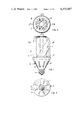
- FIG. 1 is a side elevational view of a compact fluorescent lamp unit that embodies the invention
- FIG. 5 is a similar view through the lamp unit along line V--V of FIG. 2;
- FIG. 6 is an enlarged cross-sectional view of the lamp unit along line VI--VI of FIG. 1;
- FIG. 7 is an exploded elevational view of the various components which comprise the lamp unit of FIG. 1;
- FIG. 8 is an exploded perspective view of the module subassembly employed in the lamp unit of FIG. 1 illustrating the manner in which the various components are coupled to each other and the circuit components;
- FIG. 9 is a perspective view on an enlarged scale of the plug-in fluorescent lamp component employed in the lamp unit shown in FIG. 1;
- FIG. 10 is a plan view, on an enlarged scale, of the plate-like mounting member employed in the FIG. 1 embodiment;
- FIG. 13 is a schematic of the lamp operating circuit which comprises an integral part of the compact lamp unit of FIG. 1;
- FIG. 14 is an enlarged perspective view of another form of plug-in fluorescent lamp component which can be employed in the improved lamp unit of the invention.
- FIG. 15 is an exploded perspective view of an alternate form of module subassembly which has a mounting plate that permits the ballast and starter components to be made in the form of plug-in components along with the convoluted fluorescent lamp.
- the present invention can be advantageously employed in various kinds of lamp assemblies that are suited by virtue of their small physical size and high brightness for home and office illumination, it is particularly adapted for use in conjunction with screw-in type lamp units that employ low-pressure type discharge lamps (such as fluorescent lamps) as the light source and it has, accordingly, been so illustrated and will be so described.
- low-pressure type discharge lamps such as fluorescent lamps
- a compact lamp unit 16 embodying the invention is shown in FIG. 1 and consists of three basic components--namely, (1) a low-pressure discharge lamp such as a fluorescent lamp L having a convoluted light-transmitting envelope formed of tubular vitreous material, (2) a light-transmitting housing such as a cover C that protectively encloses the lamp component, and (3) a module M that is coupled to the cover and lamp components and is terminated by a suitable base-connector 18 that is adapted to fit and engage the socket of the lighting fixture in which the lamp unit will be used.
- the convoluted fluorescent lamp L is of triple-U-bent construction and the cover C is of cylindrical shape with a domed end that is provided with a series of slot openings 19 (shown more clearly in FIG.
- the body portion 20 of the module M is tapered and cone-shaped in accordance with this particular embodiment and is also provided with a series of vent openings or apertures 21 so that a stream of cool air can flow through the unit.
- the base-connector 18 extends from the constricted end of the module M and can be of the screw-in type illustrated or of the bayonet type, depending upon the socket design of the lighting fixture or apparatus in which the lamp unit 16 will be used. As shown in FIG. 3, the vent openings 21 are arranged at spaced intervals around the conical wall 20 of the module M to provide optimum air-cooling of the lamp unit.
- a ballast component 22 is also located within the lamp unit 16 and connected to the fluorescent lamp L in the manner hereinafter described.
- the convoluted fluorescent lamp L is held in upstanding position within the cover C by a base member 24 that is secured to the sealed tubular ends of the envelope.
- the base member is fastened to a plate-like member 28 which extends transversely across the module M and is fastened to up-standing bosses 30 which protrude from the inner surface of the module body 20.
- Member 28 serves as a mounting component for the lamp L and various parts of the electrical circuit as explained hereafter.
- the fluorescent lamp L has a convoluted envelope that is formed from conventional glass tubing which has been bent to form three conjoined U-shaped segments which are so arranged that the sealed ends of the envelope are located adjacent one another.
- the lamp envelope accordingly consists of four straight tubular segments 29, 30, 31 and 32 that are joined by three U-bent segments 33, 34 and 35.
- U-bent segment 34 is desirably provided with a tubular-shaped nipple or tip 36 which provides a cool region within the lamp during operation that helps to control the mercury-vapor pressure.
- the ends of envelope segments 29, 32 are joined by base member 24 which is cemented or otherwise secured to the envelope in enclosing relationship with its sealed ends.
- the base member 24 is provided with a pair of apertured tabular portions 25 which extend laterally and can be secured with suitable fasteners to the plate-like mounting member 28 of the module M.
- Suitable contactor elements such as metal pins 27, protrude from the bottom of the lamp base 24 and are connected to electrodes sealed within the ends of the envelope, thus permitting the convoluted fluorescent lamp L to be plugged into and readily removed from the module M.
- the convoluted envelope is provided with an inner coating of a suitable phosphor material and contains an ionizable medium such as a predetermined dose of mercury and a starting gas in accordance with standard lamp-making practice.
- the tabular portions 25 of base member 24 are secured to the mounting plate 28 with screw fasteners 26 so that the convoluted fluorescent lamp L is firmly seated on the plate and locked in upstanding position within the protective cover C.
- the plate 28, in turn, is securely fastened to the module M by another set of screw fasteners 39 (see FIG. 4) that extend through suitable reinforced apertured portions 40 of the mounting plate and engage the respective bosses 30 that protrude from the inner wall of the module M.
- the base pins 27 of the fluorescent lamp L engage electrical-receptacle elements 55, 56 (FIG. 5) carried by the mounting plate 28 (as hereinafter explained and shown in FIG. 8) which elements, in turn, are connected by insulated conductors 41 and a junction block 42 to the ballast component 22 and the usual starter means consisting of a glow switch 43 and condenser 44 which start the lamp L in pre-heat fashion.
- the central part 45 of the mounting plate 28 extends into the module M and defines a box-like pocket or cavity that accommodates the lower end of the elongated ballast component 22 so that the ballast is held in stabilized upstanding position in the central opening or space defined by U-bent segments of the convoluted lamp L.
- the ballast component 22 is accordingly securely locked in telescoped and nested relationship with the U-bent segments of the fluorescent lamp L by the plate 28.
- the junction block 42 is seated against the bottom of the box-like portion 45 of the plate 28 and includes a number of screw fasteners 46 that lock the inserted ends of the various wire conductors 41 in engagement with pin contacts that protrude from the bottom of the ballast component 22 into the junction block.
- the electrical circuit elements (with the exception of the upper part of the inductive ballast 22) and various connections are accordingly located within the chamber that is defined by the body portion 20 of the module M and the mounting plate 28 that extends across the top of the module.
- the various conductors 41 are desirably held in place by suitable means such as a strip of adhesive tape 47 that is wrapped around the box-like portion 45 of the plate 28.
- the plate-like mount component 28 not only serves as an "interface” means that mechanically and electrically couples the convoluted lamp L and associated circuit components to each other and the module M, but that it does so in a manner such that it does not obstruct but actually enhances the free passage of air through the lamp unit 16 when the latter is operated in either a base-up or base-down burning position. This is achieved by making the mounting plate 28 smaller than the surrounding portion of the module M and positioning the plate so that its peripheral edges are spaced inwardly from the body 20 of the module and rim of the cover C, as shown most clearly in FIG. 6.
- the resulting space or gap between the peripheral edge of the plate 28 and the surrounding portions of the module M and cover C serves as a passageway 48 that extends around the entire circumference of the plate and is partially blocked by the arcuate outer rim of the lamp base 24.
- a "curtain-like" stream of cool air flows freely from the vented module M through the peripheral passageway 48 and upwardly through the protective cover C around the convoluted lamp L along the cover-lamp interspace and out through the vent openings 19 in the top of the cover.
- the flow of air would be in the opposite direction. The air flow thus convection-cools the fluorescent lamp L and prevents it from operating at an excessive temperature--thereby avoiding the drop in light output due to the rise in the pressure of the mercury vapor within the lamp envelope which would otherwise occur.
- the mounting plate 28 is preferably provided with an opening 49 that accommodates and is much larger than the tip segment 36 of the lamp L so that air also flows around and cools the tip segment (as indicated by the arrows).
- FIG. 6 several circumferentially spaced tabs 50 protrude from the rim of the plate 28. These tabs serve as stops for a pair of tongue-like elements 51 that effect a slip-lock juncture with slotted rim portions 52 of the module M (shown in FIG. 4).
- the protective cover C is thus releasably fastened to the module M and can be detached and removed from the unit 16 along with the fluorescent lamp L and the ballast component 22.
- cover component C, convoluted fluorescent lamp L and ballast component 22 are all releasably secured to the module subassembly in telescoped interfitting relationship by the mounting plate and various connector means described previously to provide the desired compactness and easy replacement of the lamp and ballast components.
- FIG. 8 The manner in which the plate-like mounting member 28 is coupled to the module M, the inductive ballast component 22 and other circuit elements to form an integral subassembly is shown in FIG. 8.
- the various insulated conductors 41 connect the terminals of the screw-type base connector 18 to pin contacts 54 on the bottom of the ballast component 22 by means of the junction block 42 and its screw fasteners 46, which are tightened after the ballast component has been inserted into the box-like portion 45 of the plate 28.
- the conductors 41 also connect the glow switch 43 and capacitor 44 in parallel relationship to a pair of plug-in receptacles 55 which, together with a second pair of such receptacles 56 that are connected to the base-connector 18 and junction block 42, are force-fitted into suitable apertures 57 in the mounting plate 28 and thus form a plug-in socket for the pin terminals 27 of the fluorescent lamp L.
- the plate 28 is locked in suspended transverse position within the module M (in planar relationship with its slotted rim portions 52) by screws 39 that fit into suitable spaced openings in the plate and engage the three upwardly-extending bosses 30 formed on the inner wall of the module body 20.
- the plate 28 also includes the opening 49 which accommodates the depending tip segment 36 of the lamp envelope and also serves as convection-cooling means for this critical portion of the convoluted fluorescent lamp L, as previously described.
- FIGS. 10-12 A more detailed illustration of the plate-like mounting member 28 is shown in FIGS. 10-12.
- the plate is preferably formed in one piece from suitable insulating material such as a plastic and has the aforementioned apertures 57 and opening 49 for accommodating the plug-in electrical receptacles 55, 56 and the tubular tip 36 of the envelope.
- the box-like portion 45 of the plate is also provided with a slot 58 for the pins 54 of the ballast component 22 when the latter is inserted into the harness plate.
- the portions of the plate 28 around the openings for the various screw fasteners 26, 39 and plug-in connectors 55, 56 are reinforced by bosses 38, 40 and 60 to permit the mounting plate to bear the physical load of the various mounted components without breaking.
- the ballast component 22 and cooling tip portion 36 of the lamp L are shown in phantom in FIGS. 11 and 12 to show how these parts fit into the plate 28.
- FIG. 13 is a schematic of the various circuit elements and the manner in which they are connected with the convoluted fluorescent lamp L to start and operate it when the lamp unit 16 is coupled to an alternating-current power supply.
- the starter component S (consisting of the glow switch 43 and noise-suppressing condenser 44) is connected in series with the lamp electrodes by the conductors 41 so that the lamp L starts in the conventional pre-heat fashion.
- Conductors 41 also connect the inductive ballast component 22 in series with the lamp electrodes and starter S in the usual manner to control the lamp current during operation.
- FIG. 14 An alternative form of convoluted fluorescent lamp La which can be more easily plugged into and out of the mount plate portion 28 of the module M is shown in FIG. 14.
- the lamp envelope is of the same triple-U-bent shape as in the previous embodiment but has its terminating leg portions 29a and 32a secured to a base member 24a that does not have tabular extensions and thus does not require any fasteners or screws to anchor the lamp to the harness plate.
- the plate member can be formed in such a manner that it has a shallow recess which will nestingly receive the base member 24a and thus provide a snug interfitting and force fit of the components.
- snap-fitting elements can also be provided on the sides of the base 24a and/or in the base-receiving portion of the mounting plate to provide a more positive interlocking action.
- FIG. 15 An alternate form of module-plate subassembly which permits the glow switch component to be plugged into and removed from the mounting plate along with the ballast component and convoluted fluorescent lamp is shown in FIG. 15.
- this advantageous structural arrangement is achieved by separating the glow switch from the condenser 44a and placing it within a small cylindrical container to form a component 43a that plugs into a suitable receptacle or socket 62 that is mounted on top of the plate member 28a.
- Suitable conductors (not shown) on the bottom face of the plate connect the glow-switch component 43a with the plug-in receptacles 55a, 56a when the latter are inserted into the plate apertures 57a so that the glow switch and condenser are connected in the same parallel relationship as before.
- the junction block within the module Ma is also eliminated and replaced by receptacle means (not shown) that comprises an integral part of the box-like portion 45a of the mounting plate 28a and functions as a plug-in socket for the pins 54a of the ballast component 22a.
- the protective cover C is preferably made from a suitable high-temperature plastic that is clear or translucent.
- the lamp base members 24, 24a and the body portions 20, 20a of the modules M and Ma can also be fabricated from suitable plastic that has the proper strength and temperature-resistant characteristics.
Abstract
Description
Claims (17)
Priority Applications (6)
| Application Number | Priority Date | Filing Date | Title |
|---|---|---|---|
| US06/246,502 US4375607A (en) | 1981-03-23 | 1981-03-23 | Compact lamp unit having plug-in fluorescent lamp and module components |
| GB8205113A GB2095464B (en) | 1981-03-23 | 1982-02-22 | Electric discharge lamps |
| CA000397806A CA1165797A (en) | 1981-03-23 | 1982-03-08 | Compact lamp unit having plug-in fluorescent lamp and module components |
| NL8200947A NL8200947A (en) | 1981-03-23 | 1982-03-08 | ELECTRIC LAMP UNIT. |
| DE19823210005 DE3210005A1 (en) | 1981-03-23 | 1982-03-19 | COMPACT FLUORESCENT LAMP |
| JP57044744A JPS57182902A (en) | 1981-03-23 | 1982-03-23 | Electric lamp unit |
Applications Claiming Priority (1)
| Application Number | Priority Date | Filing Date | Title |
|---|---|---|---|
| US06/246,502 US4375607A (en) | 1981-03-23 | 1981-03-23 | Compact lamp unit having plug-in fluorescent lamp and module components |
Publications (1)
| Publication Number | Publication Date |
|---|---|
| US4375607A true US4375607A (en) | 1983-03-01 |
Family
ID=22930944
Family Applications (1)
| Application Number | Title | Priority Date | Filing Date |
|---|---|---|---|
| US06/246,502 Expired - Fee Related US4375607A (en) | 1981-03-23 | 1981-03-23 | Compact lamp unit having plug-in fluorescent lamp and module components |
Country Status (6)
| Country | Link |
|---|---|
| US (1) | US4375607A (en) |
| JP (1) | JPS57182902A (en) |
| CA (1) | CA1165797A (en) |
| DE (1) | DE3210005A1 (en) |
| GB (1) | GB2095464B (en) |
| NL (1) | NL8200947A (en) |
Cited By (33)
| Publication number | Priority date | Publication date | Assignee | Title |
|---|---|---|---|---|
| US4455508A (en) * | 1980-09-11 | 1984-06-19 | U.S. Philips Corporation | Low-pressure mercury vapor discharge lamp |
| US4485331A (en) * | 1981-12-11 | 1984-11-27 | Gte Products Corporation | Fluorescent lamp holder |
| US4495443A (en) * | 1984-01-27 | 1985-01-22 | Cummings John H | Compact fluorescent lamp combination, and method of making it |
| US4503360A (en) * | 1982-07-26 | 1985-03-05 | North American Philips Lighting Corporation | Compact fluorescent lamp unit having segregated air-cooling means |
| US4503358A (en) * | 1981-06-05 | 1985-03-05 | Tokyo Shibaura Denki Kabushiki Kaisha | Fluorescent lamp having separate cooling means for ballast and fluorescent tube |
| US4546290A (en) * | 1981-05-08 | 1985-10-08 | Egyesult Izzolampa Es Villamossagi Rt. | Ballast circuits for discharge lamp |
| US4570105A (en) * | 1983-09-20 | 1986-02-11 | Engel Herman J | Electrical adapter for use in connection with fluorescent lamps |
| US4683402A (en) * | 1985-04-25 | 1987-07-28 | Truman Aubrey | Adaptors for fluorescent lamps |
| WO1987005436A1 (en) * | 1986-03-05 | 1987-09-11 | American Light Corporation | Fluorescent-bulb replacement unit for an incandescent bulb |
| US4695767A (en) * | 1984-10-25 | 1987-09-22 | Patent Treuhand Gesellschaft Fur Elektrische Gluhlampen Mbh | Single-ended fluorescent lamp-base combination |
| US4855635A (en) * | 1986-02-18 | 1989-08-08 | Gte Products Corporation | Fluorescent lamp unit with magnetic field generating means |
| US4878159A (en) * | 1988-10-11 | 1989-10-31 | Gte Products Corporation | Fluorescent lamp having removable jacket |
| US4931696A (en) * | 1987-02-26 | 1990-06-05 | Gte Products Corporation | Fluorescent lamp starter assembly |
| US5128590A (en) * | 1990-03-19 | 1992-07-07 | Walter Holzer | Compact fluorescent lamp |
| US5316473A (en) * | 1988-06-17 | 1994-05-31 | Dentsply Research & Development Corp. | Light curing apparatus and method |
| US5367229A (en) * | 1991-03-28 | 1994-11-22 | Yang Thien S | Lamp ballasts |
| US5390096A (en) * | 1992-10-22 | 1995-02-14 | Progressive Technology In Lighting, Inc. | Replacement compact fluorescent lamp assembly |
| AU662662B2 (en) * | 1990-03-19 | 1995-09-07 | Walter Holzer | Compact fluorescent lamp |
| US5717277A (en) * | 1993-04-30 | 1998-02-10 | The Regents, University Of California | Compact fluorescent lamp using horizontal and vertical insulating septums and convective venting geometry |
| US5720548A (en) * | 1995-11-14 | 1998-02-24 | Progressive Technology In Lighting, Inc. | High luminance fluorescent lamp assembly |
| US6431725B1 (en) * | 1999-06-16 | 2002-08-13 | Matsushita Electric Industrial Co., Ltd. | Bulb-shaped fluorescent lamp |
| US6502962B1 (en) * | 2000-10-23 | 2003-01-07 | Fire Products Company | Cover assembly for a light |
| DE19726919C2 (en) * | 1996-07-01 | 2003-03-27 | Matsushita Electric Ind Co Ltd | Bulb shaped fluorescent lamp |
| US20100237761A1 (en) * | 2005-04-08 | 2010-09-23 | Toshiba Lighting & Technology Corporation | Lamp having outer shell to radiate heat of light source |
| US20110080739A1 (en) * | 2009-10-02 | 2011-04-07 | Shantha Totada R | Light with Replaceable Light Source |
| US20120146513A1 (en) * | 2009-09-03 | 2012-06-14 | Koninklijke Philips Electronics N.V. | Led lamp |
| USD666750S1 (en) | 2012-02-13 | 2012-09-04 | Lighting Science Group Corporation | Luminaire |
| USD667971S1 (en) | 2010-05-04 | 2012-09-25 | Lighting Science Group Corporation | Luminaire |
| USD669607S1 (en) | 2009-05-13 | 2012-10-23 | Lighting Science Group Corporation | Luminaire |
| USD671244S1 (en) | 2010-05-04 | 2012-11-20 | Lighting Science Group Corporation | Luminaire |
| USD672480S1 (en) | 2010-05-04 | 2012-12-11 | Lighting Science Group Corporation | Luminaire |
| USD675367S1 (en) | 2009-07-23 | 2013-01-29 | Lighting Science Group Corporation | Luminaire |
| RU2777399C1 (en) * | 2021-02-09 | 2022-08-03 | Общество с ограниченной ответственностью Производственная компания "Лаборатория импульсной техники" (ООО ПК "ЛИТ") | Amalgam uv lamp |
Families Citing this family (15)
| Publication number | Priority date | Publication date | Assignee | Title |
|---|---|---|---|---|
| KR850003187Y1 (en) * | 1983-12-05 | 1985-12-24 | 신광기업주식회사 | A fluorescent lamp |
| DE3432675A1 (en) * | 1984-09-05 | 1986-03-13 | Patent-Treuhand-Gesellschaft für elektrische Glühlampen mbH, 8000 München | COMPACT LOW PRESSURE DISCHARGE LAMP |
| JPS6228310U (en) * | 1985-08-06 | 1987-02-20 | ||
| GB2209431A (en) * | 1987-09-02 | 1989-05-10 | Fook Tin Plastic Factory Limit | A discharge lamp provided with a removable ballast unit |
| JPH0677403B2 (en) * | 1988-05-17 | 1994-09-28 | 神保電器株式会社 | Lighting equipment for discharge lamps |
| DE4011213A1 (en) * | 1990-03-19 | 1991-09-26 | Holzer Walter | Compact fluorescent lamp |
| DE4037947A1 (en) * | 1990-04-09 | 1992-06-04 | Holzer Walter | Compact fluorescent lamp |
| GB2256754A (en) * | 1991-06-01 | 1992-12-16 | Thorn Lighting Ltd | Electrical connection for fluorescent lamp. |
| DE4313018A1 (en) * | 1993-04-21 | 1994-12-22 | Kuemmerling Andreas | Compact fluorescent lamp |
| DE29500786U1 (en) * | 1995-01-19 | 1995-04-06 | Piruzram Mansur | Energy saving lamp |
| DE19501500A1 (en) * | 1995-01-19 | 1996-07-25 | Mansur Piruzram | Energy-saving lamp |
| DE19509112A1 (en) * | 1995-03-16 | 1996-09-19 | Holzer Walter | Compact fluorescent lighting unit |
| DE19624860A1 (en) * | 1996-04-04 | 1997-10-09 | Peter Grimm | Compact electronic fluorescent lamp with external envelope in light bulb form |
| FR2763742A1 (en) * | 1997-05-26 | 1998-11-27 | H B Ind | Single unit compact fluorescent lamp |
| US6140751A (en) * | 1998-03-30 | 2000-10-31 | General Electric Company | Electrolytic capacitor heat sink |
Citations (6)
| Publication number | Priority date | Publication date | Assignee | Title |
|---|---|---|---|---|
| US3551736A (en) * | 1968-04-02 | 1970-12-29 | Gunther Anthony Doehner | Fluorescent lamps constructed for use in conventional light fixtures |
| US3815080A (en) * | 1973-04-12 | 1974-06-04 | F Summa | Fluorescent lamp adapter assembly |
| US4173730A (en) * | 1978-07-11 | 1979-11-06 | Westinghouse Electric Corp. | Compact fluorescent lamp unit having integral circuit means for DC operation |
| US4270071A (en) * | 1979-11-26 | 1981-05-26 | Westinghouse Electric Corp. | Composite base and ballast member for compact single-ended fluorescent lamp |
| US4311942A (en) * | 1977-09-21 | 1982-01-19 | Spellman High Voltage Electronics Corp. | Compact fluorescent lamp and method and means for magnetic arc spreading |
| US4337414A (en) * | 1979-11-26 | 1982-06-29 | Westinghouse Electric Corp. | Compact fluorescent lamp having convoluted tubular envelope of tridimensional configuration, method of making such envelope, and lighting unit incorporating such lamp |
Family Cites Families (3)
| Publication number | Priority date | Publication date | Assignee | Title |
|---|---|---|---|---|
| DE2125638A1 (en) * | 1971-05-24 | 1972-12-07 | Doehner G | Fluorescent lighting fixture |
| NL174104C (en) * | 1977-08-23 | 1984-04-16 | Philips Nv | LAMP UNIT. |
| US4300073A (en) * | 1979-02-13 | 1981-11-10 | Westinghouse Electric Corp. | Screw-in type lighting unit having a convoluted tridimensional fluorescent lamp |
-
1981
- 1981-03-23 US US06/246,502 patent/US4375607A/en not_active Expired - Fee Related
-
1982
- 1982-02-22 GB GB8205113A patent/GB2095464B/en not_active Expired
- 1982-03-08 NL NL8200947A patent/NL8200947A/en not_active Application Discontinuation
- 1982-03-08 CA CA000397806A patent/CA1165797A/en not_active Expired
- 1982-03-19 DE DE19823210005 patent/DE3210005A1/en not_active Ceased
- 1982-03-23 JP JP57044744A patent/JPS57182902A/en active Pending
Patent Citations (6)
| Publication number | Priority date | Publication date | Assignee | Title |
|---|---|---|---|---|
| US3551736A (en) * | 1968-04-02 | 1970-12-29 | Gunther Anthony Doehner | Fluorescent lamps constructed for use in conventional light fixtures |
| US3815080A (en) * | 1973-04-12 | 1974-06-04 | F Summa | Fluorescent lamp adapter assembly |
| US4311942A (en) * | 1977-09-21 | 1982-01-19 | Spellman High Voltage Electronics Corp. | Compact fluorescent lamp and method and means for magnetic arc spreading |
| US4173730A (en) * | 1978-07-11 | 1979-11-06 | Westinghouse Electric Corp. | Compact fluorescent lamp unit having integral circuit means for DC operation |
| US4270071A (en) * | 1979-11-26 | 1981-05-26 | Westinghouse Electric Corp. | Composite base and ballast member for compact single-ended fluorescent lamp |
| US4337414A (en) * | 1979-11-26 | 1982-06-29 | Westinghouse Electric Corp. | Compact fluorescent lamp having convoluted tubular envelope of tridimensional configuration, method of making such envelope, and lighting unit incorporating such lamp |
Cited By (55)
| Publication number | Priority date | Publication date | Assignee | Title |
|---|---|---|---|---|
| US4455508A (en) * | 1980-09-11 | 1984-06-19 | U.S. Philips Corporation | Low-pressure mercury vapor discharge lamp |
| US4546290A (en) * | 1981-05-08 | 1985-10-08 | Egyesult Izzolampa Es Villamossagi Rt. | Ballast circuits for discharge lamp |
| US4503358A (en) * | 1981-06-05 | 1985-03-05 | Tokyo Shibaura Denki Kabushiki Kaisha | Fluorescent lamp having separate cooling means for ballast and fluorescent tube |
| US4485331A (en) * | 1981-12-11 | 1984-11-27 | Gte Products Corporation | Fluorescent lamp holder |
| US4503360A (en) * | 1982-07-26 | 1985-03-05 | North American Philips Lighting Corporation | Compact fluorescent lamp unit having segregated air-cooling means |
| US4570105A (en) * | 1983-09-20 | 1986-02-11 | Engel Herman J | Electrical adapter for use in connection with fluorescent lamps |
| US4495443A (en) * | 1984-01-27 | 1985-01-22 | Cummings John H | Compact fluorescent lamp combination, and method of making it |
| US4695767A (en) * | 1984-10-25 | 1987-09-22 | Patent Treuhand Gesellschaft Fur Elektrische Gluhlampen Mbh | Single-ended fluorescent lamp-base combination |
| US4683402A (en) * | 1985-04-25 | 1987-07-28 | Truman Aubrey | Adaptors for fluorescent lamps |
| US4855635A (en) * | 1986-02-18 | 1989-08-08 | Gte Products Corporation | Fluorescent lamp unit with magnetic field generating means |
| WO1987005436A1 (en) * | 1986-03-05 | 1987-09-11 | American Light Corporation | Fluorescent-bulb replacement unit for an incandescent bulb |
| US4931696A (en) * | 1987-02-26 | 1990-06-05 | Gte Products Corporation | Fluorescent lamp starter assembly |
| US5316473A (en) * | 1988-06-17 | 1994-05-31 | Dentsply Research & Development Corp. | Light curing apparatus and method |
| US4878159A (en) * | 1988-10-11 | 1989-10-31 | Gte Products Corporation | Fluorescent lamp having removable jacket |
| US5128590A (en) * | 1990-03-19 | 1992-07-07 | Walter Holzer | Compact fluorescent lamp |
| AU662662B2 (en) * | 1990-03-19 | 1995-09-07 | Walter Holzer | Compact fluorescent lamp |
| US5367229A (en) * | 1991-03-28 | 1994-11-22 | Yang Thien S | Lamp ballasts |
| US5390096A (en) * | 1992-10-22 | 1995-02-14 | Progressive Technology In Lighting, Inc. | Replacement compact fluorescent lamp assembly |
| US5717277A (en) * | 1993-04-30 | 1998-02-10 | The Regents, University Of California | Compact fluorescent lamp using horizontal and vertical insulating septums and convective venting geometry |
| US5720548A (en) * | 1995-11-14 | 1998-02-24 | Progressive Technology In Lighting, Inc. | High luminance fluorescent lamp assembly |
| DE19726919C2 (en) * | 1996-07-01 | 2003-03-27 | Matsushita Electric Ind Co Ltd | Bulb shaped fluorescent lamp |
| US6431725B1 (en) * | 1999-06-16 | 2002-08-13 | Matsushita Electric Industrial Co., Ltd. | Bulb-shaped fluorescent lamp |
| US6558019B2 (en) | 1999-06-16 | 2003-05-06 | Matsushita Electric Industrial Co., Ltd. | Bulb-shaped fluorescent lamp |
| US6502962B1 (en) * | 2000-10-23 | 2003-01-07 | Fire Products Company | Cover assembly for a light |
| US20100244694A1 (en) * | 2005-04-08 | 2010-09-30 | Toshiba Lighting & Technology Corporation | Lamp having outer shell to radiate heat of light source |
| US20130148364A1 (en) * | 2005-04-08 | 2013-06-13 | Toshiba Lighting & Technology Corporation | Lamp Having Outer Shell to Radiate Heat of Light Source |
| US20100237761A1 (en) * | 2005-04-08 | 2010-09-23 | Toshiba Lighting & Technology Corporation | Lamp having outer shell to radiate heat of light source |
| US20100253200A1 (en) * | 2005-04-08 | 2010-10-07 | Toshiba Lighting & Technology Corporation | Lamp having outer shell to radiate heat of light source |
| US9772098B2 (en) | 2005-04-08 | 2017-09-26 | Toshiba Lighting & Technology Corporation | Lamp having outer shell to radiate heat of light source |
| US9249967B2 (en) | 2005-04-08 | 2016-02-02 | Toshiba Lighting & Technology Corporation | Lamp having outer shell to radiate heat of light source |
| US9234657B2 (en) | 2005-04-08 | 2016-01-12 | Toshiba Lighting & Technology Corporation | Lamp having outer shell to radiate heat of light source |
| US9103541B2 (en) | 2005-04-08 | 2015-08-11 | Toshiba Lighting & Technology Corporation | Lamp having outer shell to radiate heat of light source |
| US20100237779A1 (en) * | 2005-04-08 | 2010-09-23 | Toshiba Lighting & Technology Corporation | Lamp having outer shell to radiate heat of light source |
| US9080759B2 (en) | 2005-04-08 | 2015-07-14 | Toshiba Lighting & Technology Corporation | Lamp having outer shell to radiate heat of light source |
| US8992041B2 (en) * | 2005-04-08 | 2015-03-31 | Toshiba Lighting & Technology Corporation | Lamp having outer shell to radiate heat of light source |
| US8979315B2 (en) | 2005-04-08 | 2015-03-17 | Toshiba Lighting & Technology Corporation | Lamp having outer shell to radiate heat of light source |
| US8858041B2 (en) | 2005-04-08 | 2014-10-14 | Toshiba Lighting & Technology Corporation | Lamp having outer shell to radiate heat of light source |
| USD669607S1 (en) | 2009-05-13 | 2012-10-23 | Lighting Science Group Corporation | Luminaire |
| USD675367S1 (en) | 2009-07-23 | 2013-01-29 | Lighting Science Group Corporation | Luminaire |
| US20120146513A1 (en) * | 2009-09-03 | 2012-06-14 | Koninklijke Philips Electronics N.V. | Led lamp |
| US8860314B2 (en) * | 2009-09-03 | 2014-10-14 | Koninklijke Philips N.V. | LED lamp |
| US20110080739A1 (en) * | 2009-10-02 | 2011-04-07 | Shantha Totada R | Light with Replaceable Light Source |
| USD674928S1 (en) * | 2010-05-04 | 2013-01-22 | Lighting Science Group Corporation | Luminaire |
| USD689218S1 (en) | 2010-05-04 | 2013-09-03 | Lighting Science Group Corporation | Luminaire |
| USD676986S1 (en) | 2010-05-04 | 2013-02-26 | Lighting Science Group Corporation | Luminaire |
| USD674923S1 (en) | 2010-05-04 | 2013-01-22 | Lighting Science Group Corporation | Luminaire |
| USD676584S1 (en) | 2010-05-04 | 2013-02-19 | Lighting Science Group Corporation | Luminaire |
| USD672480S1 (en) | 2010-05-04 | 2012-12-11 | Lighting Science Group Corporation | Luminaire |
| USD726349S1 (en) | 2010-05-04 | 2015-04-07 | Lighting Science Group Corporation | Luminaire |
| USD671244S1 (en) | 2010-05-04 | 2012-11-20 | Lighting Science Group Corporation | Luminaire |
| USD667971S1 (en) | 2010-05-04 | 2012-09-25 | Lighting Science Group Corporation | Luminaire |
| USD676988S1 (en) | 2010-05-04 | 2013-02-26 | Lighting Science Group Corporation | Luminaire |
| USD676987S1 (en) | 2010-05-04 | 2013-02-26 | Lighting Science Group Corporation | Luminaire |
| USD666750S1 (en) | 2012-02-13 | 2012-09-04 | Lighting Science Group Corporation | Luminaire |
| RU2777399C1 (en) * | 2021-02-09 | 2022-08-03 | Общество с ограниченной ответственностью Производственная компания "Лаборатория импульсной техники" (ООО ПК "ЛИТ") | Amalgam uv lamp |
Also Published As
| Publication number | Publication date |
|---|---|
| DE3210005A1 (en) | 1982-10-21 |
| GB2095464A (en) | 1982-09-29 |
| GB2095464B (en) | 1985-01-09 |
| CA1165797A (en) | 1984-04-17 |
| JPS57182902A (en) | 1982-11-11 |
| NL8200947A (en) | 1982-10-18 |
Similar Documents
| Publication | Publication Date | Title |
|---|---|---|
| US4375607A (en) | Compact lamp unit having plug-in fluorescent lamp and module components | |
| US4414489A (en) | Compact electric discharge lamp-and-ballast unit, and plug-in ballast module therefor | |
| US4300073A (en) | Screw-in type lighting unit having a convoluted tridimensional fluorescent lamp | |
| US4871944A (en) | Compact lighting unit having a convoluted fluorescent lamp with integral mercury-vapor pressure-regulating means, and method of phosphor-coating the convoluted envelope for such a lamp | |
| US4688874A (en) | Arrangement in electric discharge lamps | |
| US4173730A (en) | Compact fluorescent lamp unit having integral circuit means for DC operation | |
| EP0588670B1 (en) | Lamp with integrated electronic module | |
| US4503358A (en) | Fluorescent lamp having separate cooling means for ballast and fluorescent tube | |
| US6204602B1 (en) | Compact fluorescent lamp and ballast assembly with an air gap for thermal isolation | |
| KR100228655B1 (en) | Ring-shaped fluorescent lamp & lighting apparatus | |
| US6162096A (en) | Reflector assembly socket which accepts a PL lamp | |
| US7462052B2 (en) | Lamp and socket assembly which prevents installation of an incandescent lamp | |
| US4809142A (en) | Integrated lighting device | |
| US6597106B2 (en) | Compact fluorescent lamp with a housing structure | |
| US4348612A (en) | Compact fluorescent lamp unit for three-way fluorescent lamp fixture | |
| KR940001264B1 (en) | Adapter for a single-base low pressure discharge lamp | |
| US4317069A (en) | Means and method for controlling lumen output and power consumption of phosphor excitable lamps | |
| CA1228391A (en) | Adapter | |
| JPH09265901A (en) | Circular fluorescent lamp and lighting system | |
| CA1141417A (en) | Screw-in type lighting unit having a convoluted tridimensional fluorescent lamp | |
| US5834884A (en) | Systematic configuration of compact fluorescent lamps for operation in a single-type ballast | |
| JPS6245364Y2 (en) | ||
| CA1186366A (en) | Means and method for controlling lumen output and power consumption of phosphor excitable lamps | |
| JPH0997589A (en) | Bulb fluorescent lamp device and lighting system | |
| JPS6033526Y2 (en) | lighting equipment |
Legal Events
| Date | Code | Title | Description |
|---|---|---|---|
| AS | Assignment |
Owner name: WESTINGHOUSE ELECTRIC CORPORATION, WESTINGHOUSE BL Free format text: ASSIGNMENT OF ASSIGNORS INTEREST.;ASSIGNORS:MORTON EDWARD W.;DOOLEY THOMAS E.;O MULLAN DANIEL W.;REEL/FRAME:003874/0359 Effective date: 19810319 |
|
| AS | Assignment |
Owner name: NORTH AMERICAN PHILIPS ELECTRIC CORP. Free format text: ASSIGNMENT OF ASSIGNORS INTEREST.;ASSIGNOR:WESTINGHOUSE ELECTRIC CORPORATION;REEL/FRAME:004113/0393 Effective date: 19830316 |
|
| FEPP | Fee payment procedure |
Free format text: PAYOR NUMBER ASSIGNED (ORIGINAL EVENT CODE: ASPN); ENTITY STATUS OF PATENT OWNER: LARGE ENTITY |
|
| MAFP | Maintenance fee payment |
Free format text: PAYMENT OF MAINTENANCE FEE, 4TH YEAR, PL 96-517 (ORIGINAL EVENT CODE: M170); ENTITY STATUS OF PATENT OWNER: LARGE ENTITY Year of fee payment: 4 |
|
| MAFP | Maintenance fee payment |
Free format text: PAYMENT OF MAINTENANCE FEE, 8TH YEAR, PL 96-517 (ORIGINAL EVENT CODE: M171); ENTITY STATUS OF PATENT OWNER: LARGE ENTITY Year of fee payment: 8 |
|
| FEPP | Fee payment procedure |
Free format text: MAINTENANCE FEE REMINDER MAILED (ORIGINAL EVENT CODE: REM.); ENTITY STATUS OF PATENT OWNER: LARGE ENTITY |
|
| LAPS | Lapse for failure to pay maintenance fees | ||
| FP | Lapsed due to failure to pay maintenance fee |
Effective date: 19950301 |
|
| STCH | Information on status: patent discontinuation |
Free format text: PATENT EXPIRED DUE TO NONPAYMENT OF MAINTENANCE FEES UNDER 37 CFR 1.362 |