US4369448A - Microwave antenna with radiation scattering support member elements - Google Patents
Microwave antenna with radiation scattering support member elements Download PDFInfo
- Publication number
- US4369448A US4369448A US06/269,216 US26921681A US4369448A US 4369448 A US4369448 A US 4369448A US 26921681 A US26921681 A US 26921681A US 4369448 A US4369448 A US 4369448A
- Authority
- US
- United States
- Prior art keywords
- strut
- supporting strut
- antenna
- waves
- supporting
- Prior art date
- Legal status (The legal status is an assumption and is not a legal conclusion. Google has not performed a legal analysis and makes no representation as to the accuracy of the status listed.)
- Expired - Lifetime
Links
- 230000005855 radiation Effects 0.000 title abstract description 23
- 230000001788 irregular Effects 0.000 claims description 17
- 230000003247 decreasing effect Effects 0.000 abstract description 6
- 230000000694 effects Effects 0.000 description 12
- 238000010586 diagram Methods 0.000 description 7
- 238000000034 method Methods 0.000 description 6
- 238000013459 approach Methods 0.000 description 4
- 230000001902 propagating effect Effects 0.000 description 4
- 229910052751 metal Inorganic materials 0.000 description 3
- 239000006096 absorbing agent Substances 0.000 description 2
- 239000002184 metal Substances 0.000 description 2
- 230000007423 decrease Effects 0.000 description 1
- 230000007547 defect Effects 0.000 description 1
- 239000000463 material Substances 0.000 description 1
Images


Classifications
-
- H—ELECTRICITY
- H01—ELECTRIC ELEMENTS
- H01Q—ANTENNAS, i.e. RADIO AERIALS
- H01Q19/00—Combinations of primary active antenna elements and units with secondary devices, e.g. with quasi-optical devices, for giving the antenna a desired directional characteristic
- H01Q19/02—Details
- H01Q19/021—Means for reducing undesirable effects
- H01Q19/023—Means for reducing undesirable effects for reducing the scattering of mounting structures, e.g. of the struts
Definitions
- the present invention relates to a reflector antenna intended for use in the microwave band or the millimeter wave band. More particularly, the invention relates to an antenna device having excellent wide angle radiation characteristics.
- reference numeral 1 designates a main reflector, 2 a subreflector, 3 a primary radiator, and 4 a supporting strut for supporting the subreflector.
- a spherical wave radiated by the primary radiator 3 of the reflector antenna thus constructed is converted into a plane wave upon being reflected by the subreflector mirror 2 and the main reflector 1.
- the plane wave is radiated outwardly.
- the plane wave 5 reflected by the main reflector 1 is scattered by the supporting strut 4.
- the scattered wave 6 is composed of the reflected wave from the surface and the diffracted wave from the edge.
- the section, on the main reflector side, of the conventional supporting strut 4 may be circular as shown in FIG. 2B or rectangular as shown in FIG. 2C. Therefore, the scattered waves 6 formed by these supporting struts have the radiation patterns as follows. If it is assumed that, as shown in FIG. 2A, the supporting strut 4 forms an angle ⁇ with the Z-axis when the plane wave 5 advances in the positive direction of the Z-axis, and if, as shown in FIG.
- the direction of the diffracted wave is in the form of a cone having an edge 7 as the central axis and having a half vertical angle ⁇ .
- the supporting strut 4 has a curved surface which has a continuously changing value ⁇ . Therefore, the reflected wave is radiated in the form of a circular cone which has the supporting strut 4 as its central axis and has a half vertical angle ⁇ .
- a reflected wave is produced due to a reflection surface 8 where the value ⁇ is 90 degrees and waves are refracted due to edges 7.
- the reflected wave is radiated in the negative direction along the Z axis (-Z), while the diffracted waves are radiated conically.
- FIGS. 3B and 3C The radiation patterns of the scattered waves due to the conventional supporting struts shown in FIGS. 2B and 2C are as shown in FIGS. 3B and 3C, respectively.
- the higher the density of lines shown therein the higher the field intensity level.
- the field intensity level is high in the direction of scattering, and it is not low even in the region where the value H is large. This degrades the wide angle radiation characteristics of the antenna. Therefore, the use of such an antenna may cause interference with other radio systems.
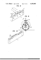
- This difficulty may be eliminated by employing a technique whereby a microwave absorber is provided on the surface of the supporting strut, or a technique whereby, as shown in FIG. 4, metal plates 9 are arranged at a certain pitch on the supporting strut 4, or a technique whereby metal elements which are shorter than the wavelength employed are irregularly arranged on the supporting strut.
- the first technique is disadvantageous in that it is impossible for the microwave absorber to completely absorb the scattered waves, and it is rather difficult to provide such a material which has satisfactory weather-proof characteristics.
- the second technique is also disadvantageous in that a grating lobe is formed according to the pitch at which the metal plates are arranged.
- the third technique has a drawback that, although the reflected wave can be scattered, it is difficult to scatter the diffracted wave.
- a triangular strut is connected to a part or the whole of a surface of the supporting strut, the length of the triangular strut in the longitudinal axis of the supporting strut being longer than the wavelength of a radio wave radiated thereby, and a structure in the form of a plate having a thickness less than the radial wavelength is connected to the edge of the triangular strut.
- a plurality of plural types of quadrangular prisms which are different in the length or height of the base thereof are irregularly arranged on a part or the whole of a surface of the supporting strut.
- a part or the whole of a surface of the supporting strut is modified into one having a special configuration.
- planar members the thickness of which is less than the radiated wavelength are provided on a portion or whole of a surface of the supporting strut on two sides thereof.
- the planar members have zigzag shaped edges, which may be similar or different between planar members.
- a strut triangular in section whose longitudinal length along the longitudinal direction of a supporting strut is longer than the radiated wavelength mounted on a part or the whole of a surface of the supporting strut.
- Structures in the form of flat plates each having a thickness less than the radiated wavelength are connected to three longitudinal edges of the triangular strut.
- FIGS. 1 and 4 are cross-sectional views of prior art antennas used in the microwave or millimeter waveband
- FIGS. 2A-2C and 3A-3C are diagrams used for illustrating radiation patterns from the antennas of FIGS. 1 and 4;
- FIGS. 5A, 5B, 6-8, 10, 11A-16A and 17-19 are diagrams illustrating various supporting strut structures for an antenna of the present invention.
- FIG. 9 is a diagram illustrating a radiation pattern of an antenna utilizing the supporting strut structure shown in FIG. 8;
- FIG. 16B is a diagram illustrating a radiation pattern of an antenna employing the supporting strut structure of the embodiment shown in FIG. 16A;
- FIG. 20A is an explanatory diagram showing wide angle radiation characteristics of the conventional antenna
- FIG. 20B is also an explanatory diagram showing wide angle radiation characteristics of the antenna using a supporting strut having a structure shown in FIG. 6.
- FIGS. 5A and 5B show a preferred embodiment of a strut structure of an antenna of the invention, of which FIG. 5A is a perspective view and FIG. 5B is a cross-sectional view.
- reference numeral 4 designates a supporting strut, 5 a plane wave passing the supporting strut, 10 a triangular strut, and 11 a plate structure.
- the cross-section of the strut 10, which is positioned parallel to the longitudinal axis of the supporting strut 4, is in the form of a triangle.
- the length of one side of the triangle adjacent the supporting strut 4 is equal to the width of the supporting strut 4, and the length of each of the remaining sides is longer than the wavelength of radiated waves.
- the length of the triangular strut 10 in the longitudinal direction of the supporting strut is longer than the wavelength.
- the plate structure 11 is a flat plate having a thickness less than the radiated wavelength. One edge of the structure 11 is connected to the lateral edge of the triangular strut 10 while the other edge is formed as a polygonal line having a number of sides each of which is longer than the wavelength.
- the triangular strut 10 is provided on the surface, faced to the main reflector side, of the supporting strut.
- the triangular strut 10 is provided on the surface of the supporting strut faced to the main reflector side.
- the structure 11 is coupled to the lateral edge of the triangular strut 10 in such a manner that it is parallel to a plane which includes both the longitudinal direction of the supporting strut and the direction of advancement of the plane wave 5.
- reference character 7a designates the aforementioned lateral edge which is the connecting line between the structure 11 and the triangular strut 7b and 7c edges which are the connecting lines between the triangular strut 10 and the supporting strut 4, and 7c an edge of the structure 11 which forms the aforementioned polygonal line.
- the scattered wave of a plane wave 5 due to the supporting strut 4 can be represented by the superposition of diffracted waves due to edges 7a, 7b, 7c and 7d and reflected waves due to the surfaces 8a and 8b.
- the reflected waves 13 due to the surfaces 8a and 8b are radiated in directions which are defined by the values ⁇ and ⁇ in expression (1). As the value ⁇ decreases, the direction of reflection approaches the direction of advancement of the plane wave 5.
- the plane wave 5 incident on the structure 10 is scattered as diffracted waves by the edge 7d.
- the edge 7d is irregularly polygonally-shaped having sides each longer than the radiated wavelength, the diffracted waves due to the edge 7d are scattered over a wide range.
- the radiation levels of the scattered waves in the region where the value H is large are reduced.
- FIG. 6 Another embodiment of the invention is shown in FIG. 6.
- the surface of a supporting strut 4, on which a triangular strut 10 is mounted is made up of a plurality of planes which are perpendicular to a plane which includes both the longitudinal direction of the supporting strut 4 and the direction of advancement of a plane wave 5.
- FIGS. 20A and 20B are explanatory diagrams showing wide angle radiation characteristics of the antenna using a conventional supporting strut and the present antenna using a supporting strut having a structure shown in FIG. 6 for the purpose of comparison, where E l designates an elevation angle.
- E l designates an elevation angle.
- the structure 11 includes a plurality of polygonal members the sides of which are different in length and which are arranged irregularly to form a polygonal line. In this case also, the radiation levels of the scattered waves are reduced.
- each of the polygonal members is triangular.
- the same effect can be obtained by employing rectangular members as the polygonal members or by employing rectangular members and triangular members in combination. Furthermore, the same effect can be obtained by rounding off some or all of the corners of the polygonal members.
- the radiation levels of the scattered waves due to the supporting strut are decreased. Accordingly, an antenna having excellent wide-angle radiation characteristics is provided.
- FIG. 8 shows another embodiment of the invention.
- reference numeral 4 designates a supporting strut, 5 a radiated plane wave, 7 edges along which quadrangular prisms are connected to the supporting strut 4, and 15 the quadrangular prisms.
- Two sides of the bottom of each quadrangular prism 15 which extend in the longitudinal direction of the supporting strut have a length and height equal to or larger than the radiated wavelength while the width of the remaining two sides of the bottom is equal to the width of the supporting strut.
- a plurality of plural types or shapes or quadrangular prisms which are different in the length or height of the sides extending in the longitudinal direction of the supporting strut, are irregularly arranged on a surface, on the main reflector side, of the supporting strut in the case of a Cassegrain antenna, and on a surface, on the reflecting mirror side, of the supporting strut in the case of a parabolic antenna.
- waves scattered due to the quadrangular prisms 15 can be represented by the superposition of reflected waves from the surfaces 16a and 16b forming the quadrangular prisms 15, waves diffracted due to the connecting lines or edges of the surfaces 16a and 16b, and waves diffracted due to the connecting lines or the edges 7 of the quadrangular prisms 15 and the supporting strut 4.
- the waves reflected due to the surfaces 16a including an edge 7 are radiated in a direction which is defined by an angle ⁇ formed between the direction of advancement of the plane wave 5 and the edge 7 and by half the angle formed between confronting surfaces 16b.
- the angle ⁇ of the plural quadrangular prisms are equal to one another but the value of ⁇ is different.
- the waves reflected due to the surfaces 16a are scattered along the generating line of a circular cone which has the supporting strut as its central axis and a half vertical angle ⁇ .
- the waves reflected due to the surfaces 16b are scattered along the H-axis.
- the waves diffracted due to the edge are scattered in the form of a circular cone which is defined by a half vertical angle ⁇ with the supporting strut as its central axis.
- the waves diffracted due to the other edges are scattered over a wide range as the angles formed between the edges and the Z-axis are different from one another. Since these quadrangular prisms are irregularly arranged, no grating lobe is produced.
- the radiation pattern of the scattered waves due to the plural quadrangular prisms is as shown in FIG. 9.
- reflection points 14a indicate the directions of the reflected waves due to the surfaces 16a
- reflection points 14b indicates the directions of the reflected waves due to the surfaces 16b.
- FIG. 10 shows yet another embodiment of the invention.
- the above-described quadrangular prisms are mounted on a surface of a supporting strut which includes a plurality of surfaces which are perpendicular to a plane which includes both the direction of advancement of transmitted waves and the longitudinal direction of the supporting strut.
- waves reflected due to the surfaces of the quadrangular prisms and waves diffracted due to the edges are scattered in a wider range, and the phases of the waves reflected due to the surfaces of the quadrangular prisms and of the waves diffracted due to the edges can be changed.
- the radiation level of the scattered waves is more effectively reduced.
- the scattered waves due to the supporting strut for the primary radiator or the subreflector obstructing the passage of the transmitted waves in the antenna of the invention are scattered over a wide range by irregularly arranging on a part or the whole of a surface of the supporting strut a plurality of plural types or shapes of quadrangular prisms with the length and height of two sides of the bottom of each quadrangular prism which extend in the longitudinal direction of the supporting strut being equal to or larger than the wavelength, the length of the remaining two sides being equal to or smaller than the width of the supporting strut, and the lengths or heights of the sides of the bottoms of the quadrangular prisms which extend in the longitudinal direction of the supporting strut being different from one another. Therefore, the radiation level of the scattered waves is reduced.
- FIG. 11A shows another preferred embodiment of the invention.
- reference numeral 4 designates the supporting strut
- 5 is a radiated plane wave
- a part or the whole of a surface, on the main reflector side, of the supporting strut is made up of a plurality of surfaces 19 perpendicular to a plane which includes both the longitudinal direction of the supporting strut 4 and the direction of advancement of the plane wave 5 in the case of a Cassegrain antenna.
- a part or the whole of a surface, on the reflector side, of the supporting strut is made up of a plurality of surfaces 19 similar to those described above. Sections of the supporting strut in planes including the aforementioned two directions have the same configuration, and each section has an edge in the form of a plygonal line with sides each longer than the radiated wavelength.
- waves scattered due to the supporting strut 4 can be represented by the superposition of waves reflected 10 due to the surfaces 19 and waves diffracted due to the polygonal edge 7.
- the diffracted waves are scattered over a wide range as the edge 18 is in the form of an irregular polygonal line.
- FIG. 12A Yet another embodiment of the invention is shown in FIG. 12A.
- the configurations of sections in given planes including both the longitudinal direction of the supporting strut and the direction of advancement of a plane wave 5 are the same, and each of the sections is in the form of an irregular polygonal line having segments each longer than the radiated wavelength.
- the configuration, on the reflector side, of a section in a plane perpendicular to the "shadow" of the supporting strut projected onto the effective area is formed by two sides which form an angle ⁇ with the direction of advancement of the plane waves 5. Therefore, by decreasing the angle ⁇ , it is possible to make the directions of the reflected waves 10 approach the direction of advancement of the plane waves 5. Furthermore, since the surface 19 of the supporting strut is irregular, the phases of the reflected waves are made different, and accordingly the field strengths of the scattered waves is reduced.
- a plurality of surfaces are formed which are symmetrical with a plane which includes both the longitudinal direction of the supporting strut 4 and the direction of advancement of the plane waves 5 facing in various directions.
- the configuration of a section in the plane of symmetry is in the form of an irregular polygonal line composed of segments each being longer than the radiated wavelength.
- FIG. 13A shows an embodiment of the present invention in which 4 is the support pole structure, 5 is an incident plane wave and 21 is a planar member.
- the planar member 21 is a plate having a thickness smaller than the radiated wavelength.
- One end of the planar member 21 is connected to the supporting strut 4 along the length thereof while the other end is irregularly zigzag shaped and has a length greater than the radiated wavelength.
- the planar member 21 is connected to a main reflector side surface of the supporting strut 4 if the antenna is of Cassegrain type or to a reflector side surface of the supporting strut 4 if the antenna is a parabolic type, wherein the member lies in a plane parallel to a plane containing the lengthwise direction of the supporting strut 4 and the propagating direction of the plane waves 5.
- a plane wave 5 incident on the planar member 21 becomes a diffraction wave due to the edge 7 and is scattered. Since the length of the edge 7 is greater than the radiated wavelength and the shape thereof is an irregularly zigzag, waves diffracted by the edge 7 are widely scattered thereby reducing the field strength of the diffracted waves.
- the same effect may be obtained by irregularly arranging a plurality of protrusions each having different length or size instead of the planar member having the zigzag shape, as shown in FIG. 13B. Therefore, since a portion of the incident plane waves 5 are widely scattered, the field strength of the waves scattered by the support pole structure is reduced.
- the protrusions are shown as being triangular in shape.
- the same effect can be obtained by providing protrusions having rectangular shapes or combination of rectangular shapes and triangle shapes.
- the same effect is also obtainable by rounding corners of a portion or the whole of the irregular zigzag shapes.
- FIG. 14A shows an embodiment of the present invention in which 4 is the supporting strut, 5 is the incident plane wave and 23 indicates two planar members.
- Each planar member 23 is a plate having a thickness less than the radiated wavelength.
- One end of the planar member 23 is connected to the supporting strut 4 along the length thereof while the other end is irregularly zigzag shaped having segments with a length greater than the radiated wavelength.
- planar members 23 are attached on either side of a main reflector side surface of the supporting strut 4 if the antenna is of Cassegrain type or to both sides of a reflector side surface of the supporting strut 4 if the antenna is a parabolic type, such that the planar members lie in planes parallel to a plane containing the lengthwise direction of the supporting strut 4 and the propagating direction of the plane waves 5.
- a plane wave 5 incident on the plane member 23 reflected by the supporting strut 4 becomes a diffracted wave due to an edge 7 of the planar members.
- the diffracted waves are scattered as shown in FIG. 14B.
- a portion of a reflected wave 25 which propagates toward the planar members 23 is scattered again by the edges 7. Since the length of each edge 7 is greater than the radiated wavelength and the shape thereof is an irregularly zigzag, waves diffracted due to the edges 7 are widely scattered. Since the phases thereof are different, the field strength of the scattered waves, which are a combination of the waves reflected and the diffracted waves, is reduced.
- the same effect may be obtained by irregularly arranging a plurality of protrusions each having different length or size instead of the planar members having the zigzag shape as shown in FIG. 15.
- the protrusions are triangular in shape.
- the same effect can be obtained by providing protrusions having a rectangular shape or combinations of rectangular and triangle shapes.
- FIGS. 14A, 14B and 15 although a case where the plate members 23 have the same configuration are attached to the both sides of the supporting strut 4 has been described, the same effect may be obtained by making the shapes of the plate member 23 different or by rounding corners of a portion or the whole of the irregular zigzag shapes.
- 4 is the supporting strut
- 5 is an incident plane wave
- 27 is a triangular strut.
- the cross-sectional shape of the strut 27 taken alone a plane orthogonal to the lengthwise direction of the supporting strut 4 is triangular with the length of the base of the triangle, with which the triangular strut is connected to the supporting strut, being equal to the width of the supporting strut 4.
- the lengths of the remaining two sides of the triangle are longer than the radiated wavelength, and the length of the triangular strut 27 along the supporting strut is longer than the radiated wavelength.
- the triangular strut 27 is formed on the supporting strut on the side of a surface of a main reflector if the antenna is of the Cassegrain type or formed on the supporting strut on the side of the reflector supported thereby if the antenna is of a parabolic type.
- An edge 28a is formed by connecting apexes of cross-sectional triangles of the triangular strut 27 and edges 28b and 28c form connecting portions to the supporting strut 4.
- a portion of incident plane waves 5 scattered by the supporting strut 4 is represented by a combination of waves diffraction due to the edges 28a, 28b and 28c and waves reflected due to planes 29a and 29b.
- the direction of the waves reflected due to the planes 29a and 29b are determined by ⁇ and ⁇ according to equation 1. Therefore, by making the value of ⁇ small, the reflected direction 30 is made closer to the propagating direction of the plane waves 5. Therefore, the radiation pattern of the scattered waves is as shown in FIG. 16B. Although there may be left some diffraction waves due to the edge 28a, it is possible to reduce the field strength of the scattered waves in the area where H is large.
- FIG. 17 shows another embodiment in which the surface configuration of the supporting strut 4 to be mounted on the triangular strut structure 27 is composed of a plurality of planes orthogonal to the plane containing the lengthwise direction of the supporting strut 4 and the propagating direction of the plane waves 5.
- reference numeral 4 designates the supporting strut, 5 the incident plane wave, 33 a triangular prism, and 30a-30c planar members.
- the configuration of a section of the strut 33 perpendicular to the longitudinal axis of the supporting strut 4 is such that the length of two sides of the bottom of the triangular strut, which is mounted to the supporting strut 4, is equal to the width of the supporting strut 4, the remaining two sides are longer than the radiated wavelength, and the length of the triangular strut 33 along the longitudinal axis of the supporting strut 1 is longer than the radiated wavelength.
- Each planar member 30a-30c is in the form of a flat plate having one edge connected to a longitudinal edge of the triangular strut 33 and another edge which is in the form of a polygonal line composed of segments each longer than the radiated wavelength.
- the triangular strut is mounted on a surface, on the main reflector mirror side, of the supporting strut in the case of a Cassegrain antenna, and on a surface on the reflector side of the supporting strut in the case of a parabolic antenna.
- the planar members 30a-30b are connected to respective three longitudinal edges of the triangular strut 33 in such a manner that they are in parallel with a plane which includes both the longitudinal direction of the supporting strut and the direction of advancement of the plane waves 5.
- the planar members 30a, 30b and 30c have edges 31a, 31b and 31c, respectively.
- An edge 31d is the connecting line of the member 30a and the triangular strut 33.
- the triangular strut 33 has side surfaces 32a and 32b extending longitudinally.
- the scattered waves can be represented by the superposition of waves diffracted due to the edges 31a, 31b, 31c and 31d and waves reflected due to the surfaces 32a and 32b. If the half vertical angle ⁇ of the triangular section of the triangular strut 33 is decreased, then the field strength of the waves diffracted due to the edge 31d are reduced. Also, the directions of advancement of the waves reflected due to the edge 31d then approaches the planar members 30b and 30c.
- edges 31a, 31b and 31c of the planar members 30a, 30b and 30c are each in the form of an irregular polygonal line composed of segments longer than the radiated wavelength, the plane waves 5 incident on these edges and the resulting scattered waves are scattered as diffracted waves with different phases over a wide range. Therefore, the scattered waves are reduced in field strength.
- FIG. 19 shows another embodiment of the invention in which a surface of the supporting strut 4 on which a triangular strut 33 and planar members 30a, 30b and 30c are mounted is made up of a plurality of surfaces which are perpendicular to a plane which includes both the longitudinal direction of the supporting strut and the direction of advancement of plane waves 5.
- the reflected waves and the diffracted waves are made different in direction and in phase. Therefore, the scattered waves are reduced in radiation level.
- planar members used in the embodiments of FIGS. 18A and 19 are formed with a plurality of triangular or rectangular members.
- the same effect can be obtained by employing planar members which include a plurality of triangular or rectangular members which have different side lengths or sizes and are arranged irregularly. Furthermore, the same effect can be obtained by rounding off the protruding corners of some or all of the triangular or rectangular members.
- each through-hole should be conical.
Abstract
Description
Claims (17)
Applications Claiming Priority (14)
| Application Number | Priority Date | Filing Date | Title |
|---|---|---|---|
| JP7454580A JPS56169903A (en) | 1980-06-03 | 1980-06-03 | Antenna device |
| JP55-74546 | 1980-06-03 | ||
| JP7454680A JPS56169904A (en) | 1980-06-03 | 1980-06-03 | Antenna device |
| JP55-74547 | 1980-06-03 | ||
| JP7454880A JPS56169906A (en) | 1980-06-03 | 1980-06-03 | Antenna device |
| JP55-74548 | 1980-06-03 | ||
| JP55-17545 | 1980-06-03 | ||
| JP7454780A JPS56169905A (en) | 1980-06-03 | 1980-06-03 | Antenna device |
| JP55-74550 | 1980-06-03 | ||
| JP7454480A JPS56169902A (en) | 1980-06-03 | 1980-06-03 | Antenna device |
| JP55-74549 | 1980-06-03 | ||
| JP7455080A JPS56169908A (en) | 1980-06-03 | 1980-06-03 | Antenna device |
| JP55-74544 | 1980-06-03 | ||
| JP7454980A JPS56169907A (en) | 1980-06-03 | 1980-06-03 | Antenna device |
Publications (1)
| Publication Number | Publication Date |
|---|---|
| US4369448A true US4369448A (en) | 1983-01-18 |
Family
ID=27565211
Family Applications (1)
| Application Number | Title | Priority Date | Filing Date |
|---|---|---|---|
| US06/269,216 Expired - Lifetime US4369448A (en) | 1980-06-03 | 1981-06-02 | Microwave antenna with radiation scattering support member elements |
Country Status (2)
| Country | Link |
|---|---|
| US (1) | US4369448A (en) |
| CA (1) | CA1172354A (en) |
Cited By (7)
| Publication number | Priority date | Publication date | Assignee | Title |
|---|---|---|---|---|
| US4761055A (en) * | 1986-03-10 | 1988-08-02 | Helmut K. Pinsch Gmbh & Co. | Retroreflector for the reflection of electromagnetic rays |
| DE4024262A1 (en) * | 1990-07-31 | 1992-02-13 | Messerschmitt Boelkow Blohm | Radar screening device for aircraft - uses abutting triangles of screening film along both sides of sharply tapered edge |
| US6052078A (en) * | 1998-11-12 | 2000-04-18 | Northrop Grumman Corporation | Apparatus for overcoming the blockage effect of an object in the path of a radiating beam of RF energy |
| US20030207083A1 (en) * | 1999-12-23 | 2003-11-06 | Krister Hansson | Process for the manufacturing of surface elements |
| EP1643590A1 (en) * | 2004-10-04 | 2006-04-05 | EMS Technologies Canada, Limited | Electromagnetic bandgap device for attenna structures |
| US8766865B2 (en) | 2009-10-21 | 2014-07-01 | Mitsubishi Electric Corporation | Antenna device |
| US20150325921A1 (en) * | 2013-06-28 | 2015-11-12 | Associated Universities, Inc. | Randomized surface reflector |
Citations (5)
| Publication number | Priority date | Publication date | Assignee | Title |
|---|---|---|---|---|
| US3296685A (en) * | 1962-05-31 | 1967-01-10 | Sylvania Electric Prod | Method of making dielectric foam antenna |
| US3396396A (en) * | 1965-11-30 | 1968-08-06 | Air Force Usa | Aircraft nose radome with ceramic cover mounted on metallic framework |
| US3530469A (en) * | 1968-06-26 | 1970-09-22 | North American Rockwell | Energy impingement device |
| US4148039A (en) * | 1977-07-05 | 1979-04-03 | The Boeing Company | Low reflectivity radome |
| US4189731A (en) * | 1978-06-12 | 1980-02-19 | General Dynamics Electronics Division | Radome with tilted dielectric strips |
-
1981
- 1981-05-29 CA CA000378683A patent/CA1172354A/en not_active Expired
- 1981-06-02 US US06/269,216 patent/US4369448A/en not_active Expired - Lifetime
Patent Citations (5)
| Publication number | Priority date | Publication date | Assignee | Title |
|---|---|---|---|---|
| US3296685A (en) * | 1962-05-31 | 1967-01-10 | Sylvania Electric Prod | Method of making dielectric foam antenna |
| US3396396A (en) * | 1965-11-30 | 1968-08-06 | Air Force Usa | Aircraft nose radome with ceramic cover mounted on metallic framework |
| US3530469A (en) * | 1968-06-26 | 1970-09-22 | North American Rockwell | Energy impingement device |
| US4148039A (en) * | 1977-07-05 | 1979-04-03 | The Boeing Company | Low reflectivity radome |
| US4189731A (en) * | 1978-06-12 | 1980-02-19 | General Dynamics Electronics Division | Radome with tilted dielectric strips |
Cited By (16)
| Publication number | Priority date | Publication date | Assignee | Title |
|---|---|---|---|---|
| US4761055A (en) * | 1986-03-10 | 1988-08-02 | Helmut K. Pinsch Gmbh & Co. | Retroreflector for the reflection of electromagnetic rays |
| DE4024262A1 (en) * | 1990-07-31 | 1992-02-13 | Messerschmitt Boelkow Blohm | Radar screening device for aircraft - uses abutting triangles of screening film along both sides of sharply tapered edge |
| US6052078A (en) * | 1998-11-12 | 2000-04-18 | Northrop Grumman Corporation | Apparatus for overcoming the blockage effect of an object in the path of a radiating beam of RF energy |
| US9636922B2 (en) | 1999-12-23 | 2017-05-02 | Pergo (Europe) Ab | Process for the manufacturing of surface elements |
| US20030207083A1 (en) * | 1999-12-23 | 2003-11-06 | Krister Hansson | Process for the manufacturing of surface elements |
| US10464339B2 (en) | 1999-12-23 | 2019-11-05 | Pergo (Europe) Ab | Process for the manufacturing of surface elements |
| US8944543B2 (en) | 1999-12-23 | 2015-02-03 | Pergo (Europe) Ab | Process for the manufacturing of surface elements |
| US8950138B2 (en) | 1999-12-23 | 2015-02-10 | Pergo (Europe) Ab | Process for the manufacturing of surface elements |
| US9656476B2 (en) | 1999-12-23 | 2017-05-23 | Pergo (Europe) Ab | Process for the manufacturing of surface elements |
| US9321299B2 (en) | 1999-12-23 | 2016-04-26 | Pergo (Europe) Ab | Process for the manufacturing of surface elements |
| US9636923B2 (en) | 1999-12-23 | 2017-05-02 | Pergo (Europe) Ab | Process for the manufacturing of surface elements |
| US9409412B2 (en) | 1999-12-23 | 2016-08-09 | Pergo (Europe) Ab | Process for the manufacturing of surface elements |
| EP1643590A1 (en) * | 2004-10-04 | 2006-04-05 | EMS Technologies Canada, Limited | Electromagnetic bandgap device for attenna structures |
| US8766865B2 (en) | 2009-10-21 | 2014-07-01 | Mitsubishi Electric Corporation | Antenna device |
| US9343815B2 (en) * | 2013-06-28 | 2016-05-17 | Associated Universities, Inc. | Randomized surface reflector |
| US20150325921A1 (en) * | 2013-06-28 | 2015-11-12 | Associated Universities, Inc. | Randomized surface reflector |
Also Published As
| Publication number | Publication date |
|---|---|
| CA1172354A (en) | 1984-08-07 |
Similar Documents
| Publication | Publication Date | Title |
|---|---|---|
| US3039097A (en) | Frequency-sensitive rapid-scanning antenna | |
| EP0530038A1 (en) | Serrated electromagnetic absorber | |
| US4369448A (en) | Microwave antenna with radiation scattering support member elements | |
| JP3113510B2 (en) | Elliptical beam antenna device | |
| Murphy | Aperture efficiencies of large axisymmetric reflector antennas fed by conical horns | |
| US4477816A (en) | Corrugated antenna feed horn with means for radiation pattern control | |
| GB2145569A (en) | Reflector antenna | |
| US4460901A (en) | Integrated antenna-radome structure that functions as a self-referencing interferometer | |
| GB2081023A (en) | Reflector antenna | |
| US5903241A (en) | Waveguide horn with restricted-length septums | |
| CN108682968B (en) | Single-feed three-beam low-RCS super-surface included angle reflector antenna | |
| US4607260A (en) | Asymmetrically configured horn antenna | |
| US4468673A (en) | Frequency scan antenna utilizing supported dielectric waveguide | |
| KR100366070B1 (en) | antenna | |
| Park et al. | Angular independency of a parallel-plate Luneburg lens with hexagonal lattice and circular metal posts | |
| RU2099836C1 (en) | Broadband four-beam mirror antenna (options) | |
| US4488157A (en) | Slot array antenna assembly | |
| RU2650832C1 (en) | On-board x-band active phase antenna array with an increased scanning sector | |
| RU2278453C1 (en) | Radar antenna of reduced effective dissipation area | |
| RU2119215C1 (en) | Broadband antenna with sector-shaped directional pattern in n plane | |
| US5075692A (en) | Antenna system | |
| JPH0680971B2 (en) | Dielectric loaded antenna with reflector | |
| US4355316A (en) | Offset J-hook reflector antenna | |
| Wilkinson et al. | Cassegrain systems | |
| JPS62204605A (en) | Circularly polarized wave shaped beam antenna |
Legal Events
| Date | Code | Title | Description |
|---|---|---|---|
| AS | Assignment |
Owner name: MITSUBISHI DENKI KABUSHIKI KAISHA, NO. 2-3, MARUNO Free format text: ASSIGNMENT OF ASSIGNORS INTEREST.;ASSIGNORS:OGAWA, AKIYOSHI;KATAGI, TAKASHI;EBISUI, TAKASHI;AND OTHERS;REEL/FRAME:004047/0289 Effective date: 19800307 Owner name: KOKUSAI DENSHIN DENWA CO., LTD., NO 3-2, NISHI-SHI Free format text: ASSIGNMENT OF ASSIGNORS INTEREST.;ASSIGNORS:OGAWA, AKIYOSHI;KATAGI, TAKASHI;EBISUI, TAKASHI;AND OTHERS;REEL/FRAME:004047/0289 Effective date: 19800307 |
|
| STCF | Information on status: patent grant |
Free format text: PATENTED CASE |
|
| MAFP | Maintenance fee payment |
Free format text: PAYMENT OF MAINTENANCE FEE, 4TH YEAR, PL 96-517 (ORIGINAL EVENT CODE: M170); ENTITY STATUS OF PATENT OWNER: LARGE ENTITY Year of fee payment: 4 |
|
| MAFP | Maintenance fee payment |
Free format text: PAYMENT OF MAINTENANCE FEE, 8TH YEAR, PL 96-517 (ORIGINAL EVENT CODE: M171); ENTITY STATUS OF PATENT OWNER: LARGE ENTITY Year of fee payment: 8 |
|
| FEPP | Fee payment procedure |
Free format text: PAYOR NUMBER ASSIGNED (ORIGINAL EVENT CODE: ASPN); ENTITY STATUS OF PATENT OWNER: LARGE ENTITY |
|
| FEPP | Fee payment procedure |
Free format text: PAYER NUMBER DE-ASSIGNED (ORIGINAL EVENT CODE: RMPN); ENTITY STATUS OF PATENT OWNER: LARGE ENTITY |
|
| FEPP | Fee payment procedure |
Free format text: PAYOR NUMBER ASSIGNED (ORIGINAL EVENT CODE: ASPN); ENTITY STATUS OF PATENT OWNER: LARGE ENTITY |
|
| MAFP | Maintenance fee payment |
Free format text: PAYMENT OF MAINTENANCE FEE, 12TH YEAR, LARGE ENTITY (ORIGINAL EVENT CODE: M185); ENTITY STATUS OF PATENT OWNER: LARGE ENTITY Year of fee payment: 12 |