US43628A - Improved candle-holder - Google Patents
Improved candle-holder Download PDFInfo
- Publication number
- US43628A US43628A US43628DA US43628A US 43628 A US43628 A US 43628A US 43628D A US43628D A US 43628DA US 43628 A US43628 A US 43628A
- Authority
- US
- United States
- Prior art keywords
- candle
- holder
- flanges
- seen
- cup
- Prior art date
- Legal status (The legal status is an assumption and is not a legal conclusion. Google has not performed a legal analysis and makes no representation as to the accuracy of the status listed.)
- Expired - Lifetime
Links
- 230000037431 insertion Effects 0.000 description 2
- 238000003780 insertion Methods 0.000 description 2
- 239000000463 material Substances 0.000 description 2
- 210000004905 finger nail Anatomy 0.000 description 1
- 239000002184 metal Substances 0.000 description 1
Images
Classifications
-
- F—MECHANICAL ENGINEERING; LIGHTING; HEATING; WEAPONS; BLASTING
- F21—LIGHTING
- F21V—FUNCTIONAL FEATURES OR DETAILS OF LIGHTING DEVICES OR SYSTEMS THEREOF; STRUCTURAL COMBINATIONS OF LIGHTING DEVICES WITH OTHER ARTICLES, NOT OTHERWISE PROVIDED FOR
- F21V35/00—Candle holders
Definitions
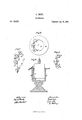
- Figure 1 represents a perspective view of the candleholder; Fig. 2, a top view of the candle-stick and candle-holder with the candle represented in section; Fig. 3, a top view of the candleholder; Fig. 4, a vertical section of the candle-stick and candle holder and a side view of the candle.
- the candle-holder consists of a bent body, 0 O O, terminating into upright flanges A A A, the flanges being separated from each other by vertical slots B B, the lower ends ofthese slots being at some height above the lower edge of the body 0 O O of the candle-holder, and -formin g circular holes 0 O of a diameter somewhat larger than the width of each slot B.
- the flanges A A A are made elastic so as to act as springs.
- a A are bent a little inward, as will be seen in Fig. 1, and then their upper and outer edges, J J, are sharp.
- the object of this candle-holder is to firmly secure candles of various thicknesses in the cups of candlesticks, and without the necessity of wrapping paper or anything else around the into the cup F of the candle-stick M, during which operation the part A O of the candleholder comes to rest against the inner surface of the cup F, as seen in Fig. 2, while the flanges A A are pressed against and partially made to embed themselves into the surface of the candle, as represented in Fig. 2
- the flaps E E E are slightly inclined, so that their outer edges are somewhat elevated above the rim H of the cup when the candle-holder has been pressed down as far as it will go. Thus it will be easy to insert the finger-nails between the flaps and the rim, and raise the candleholder and candle end out of the cup when the candle has been burned out or nearly burned out, and the candle end has to be removed.
- the flanges A A A it will be seen,
- the shape of the candle-holder may be varied so that there are but two flanges A A, or any larger number of flanges, provided that they form a 'segment only of a polygon, so as to presentft-wo sharp-edged ends.
Landscapes
- Engineering & Computer Science (AREA)
- General Engineering & Computer Science (AREA)
- Arrangement Of Elements, Cooling, Sealing, Or The Like Of Lighting Devices (AREA)
Description
E. DAIRE.
Candlestick.
No. 43,628. I 4 Patented July 19, 864.
. 75 K fizz/safer.
UNITED STATES PATENT OF ICE.
EMILE DAIRE, OF AMIENS, FRANCE.
IMPROVED CANDLE-HOLDER.
Specification forming part of Letters Patent No. 43,628, dated July 19, 1864.
To all whom it may concern:
Be it known that I, EMILE DAIRE, of-
Amiens, in the Empire of France, have invented a new and useful Improvement in landle-Holders; and I do hereby declare that the following is a full and exact description thereof, reference being had to the accompanying drawings, and to the letters of reference marked thereon. V The nature of this invention consists in the combination of the bent body of a candle holder with elastic sharp-edged flanges, inclined flaps and horizontal bottom guard, when said candle-holder forms a segment of a polygon for the purpose'of insertion between the candle and the inside of the cup of the candle-stick, as hereinafter to be described.
In the accompanying drawings, Figure 1 represents a perspective view of the candleholder; Fig. 2, a top view of the candle-stick and candle-holder with the candle represented in section; Fig. 3, a top view of the candleholder; Fig. 4, a vertical section of the candle-stick and candle holder and a side view of the candle.
The candle-holder consists of a bent body, 0 O O, terminating into upright flanges A A A, the flanges being separated from each other by vertical slots B B, the lower ends ofthese slots being at some height above the lower edge of the body 0 O O of the candle-holder, and -formin g circular holes 0 O of a diameter somewhat larger than the width of each slot B. By this means, and on account of the thinness of the metal or other suitable material of which the candle-holder is made, the flanges A A A are made elastic so as to act as springs. A A are bent a little inward, as will be seen in Fig. 1, and then their upper and outer edges, J J, are sharp. The upper ends of the flanges A A A are bent back so as to form flaps E E E, which are nearly horizontal, but slightly upward inclined from the flanges back, as seen in Fig. 4. The lower edge of the part 0 of the candle-holder is bent inward, so as to form a horizontal guard, It,
as seen in Figs. 1, 3, and 4. The object of this candle-holder is to firmly secure candles of various thicknesses in the cups of candlesticks, and without the necessity of wrapping paper or anything else around the into the cup F of the candle-stick M, during which operation the part A O of the candleholder comes to rest against the inner surface of the cup F, as seen in Fig. 2, while the flanges A A are pressed against and partially made to embed themselves into the surface of the candle, as represented in Fig. 2
by dotted lines, so as to firmly secure the candle. When the candle is of very hard material, it will be well to hold the candle so that its bottom end he at some height above the guard It, while both are being inserted into the cup. When the candle-holder has been completely inserted, as seen in Fig. 4, the candle is pressed down until its bottom end comes to rest against the guard R. While the candle is being pressed down the sharp edges J J cut into the surface of the candle and cause the flanges A A to embed themselves partially into the surface of the candle, as seen in Fig. 4, and thus to take a firm hold of the candle. The flaps E E E are slightly inclined, so that their outer edges are somewhat elevated above the rim H of the cup when the candle-holder has been pressed down as far as it will go. Thus it will be easy to insert the finger-nails between the flaps and the rim, and raise the candleholder and candle end out of the cup when the candle has been burned out or nearly burned out, and the candle end has to be removed. The flanges A A A, it will be seen,
form a segment of a polygon, with the sharp edges J J at both ends.
It will be understood that the shape of the candle-holder may be varied so that there are but two flanges A A, or any larger number of flanges, provided that they form a 'segment only of a polygon, so as to presentft-wo sharp-edged ends.
Having described my invention,\vhat I the purpose of insertion between the candle claim therein as new, and desire to secure by Letters Patent, is
The combination of the bent body 0 O O of a candle-holder, with elastic sharp-edged flanges A A A,ine1ined flaps E E E, and horizontal bottom guard, B, when said candle-holder forms a segment of a polygon, for
EMILE QDAIR-E.
Witnesses HEY. CASTELBON, E. SHERMAN GOULD.
Publications (1)
| Publication Number | Publication Date |
|---|---|
| US43628A true US43628A (en) | 1864-07-19 |
Family
ID=2113194
Family Applications (1)
| Application Number | Title | Priority Date | Filing Date |
|---|---|---|---|
| US43628D Expired - Lifetime US43628A (en) | Improved candle-holder |
Country Status (1)
| Country | Link |
|---|---|
| US (1) | US43628A (en) |
Cited By (2)
| Publication number | Priority date | Publication date | Assignee | Title |
|---|---|---|---|---|
| US6409501B1 (en) * | 1998-06-18 | 2002-06-25 | Lumi-Lite Candle Company, Inc. | Candle with surrounding decorative combustible material |
| US20070223238A1 (en) * | 2006-03-27 | 2007-09-27 | The Lamson & Sessions Co. | Candle mounting device |
-
0
- US US43628D patent/US43628A/en not_active Expired - Lifetime
Cited By (2)
| Publication number | Priority date | Publication date | Assignee | Title |
|---|---|---|---|---|
| US6409501B1 (en) * | 1998-06-18 | 2002-06-25 | Lumi-Lite Candle Company, Inc. | Candle with surrounding decorative combustible material |
| US20070223238A1 (en) * | 2006-03-27 | 2007-09-27 | The Lamson & Sessions Co. | Candle mounting device |
Similar Documents
| Publication | Publication Date | Title |
|---|---|---|
| US837240A (en) | Candle-socket. | |
| US1320109A (en) | Cauble-wick support | |
| US1195657A (en) | Caetdle-holdeb | |
| US422989A (en) | Alfred stelzner | |
| US43628A (en) | Improved candle-holder | |
| US2213203A (en) | Candle holder | |
| US1259921A (en) | Night-light. | |
| US806402A (en) | Support for trees. | |
| US38672A (en) | Elliott p | |
| US606850A (en) | Chimney-holder | |
| US43397A (en) | Improvement in lamp-shade holders | |
| US539199A (en) | Candlestick | |
| US35154A (en) | Improvement in night-lamps | |
| US35866A (en) | Improvement in lamp-chimneys | |
| US1103696A (en) | Attachment for lamp-burners. | |
| US1122049A (en) | Lamp-chimney. | |
| US549729A (en) | Christmas-tree candle-holder | |
| US150572A (en) | Improvement in decorative lanterns | |
| US49290A (en) | Improvement in lanterns | |
| US752583A (en) | Lamp-reflector | |
| US568314A (en) | Ments | |
| US913724A (en) | Chimney-holder for lamp-burners. | |
| US41794A (en) | Improvement in lamps | |
| US1140415A (en) | Lamp-burner. | |
| US568196A (en) | Joseph frenzel |