US4361118A - Cooling apparatus of combustion chambers for water-cooled engines - Google Patents
Cooling apparatus of combustion chambers for water-cooled engines Download PDFInfo
- Publication number
- US4361118A US4361118A US06/211,675 US21167580A US4361118A US 4361118 A US4361118 A US 4361118A US 21167580 A US21167580 A US 21167580A US 4361118 A US4361118 A US 4361118A
- Authority
- US
- United States
- Prior art keywords
- water jacket
- water
- cap
- port
- conduit
- Prior art date
- Legal status (The legal status is an assumption and is not a legal conclusion. Google has not performed a legal analysis and makes no representation as to the accuracy of the status listed.)
- Expired - Lifetime
Links
Images

Classifications
-
- F—MECHANICAL ENGINEERING; LIGHTING; HEATING; WEAPONS; BLASTING
- F01—MACHINES OR ENGINES IN GENERAL; ENGINE PLANTS IN GENERAL; STEAM ENGINES
- F01P—COOLING OF MACHINES OR ENGINES IN GENERAL; COOLING OF INTERNAL-COMBUSTION ENGINES
- F01P11/00—Component parts, details, or accessories not provided for in, or of interest apart from, groups F01P1/00 - F01P9/00
- F01P11/02—Liquid-coolant filling, overflow, venting, or draining devices
-
- F—MECHANICAL ENGINEERING; LIGHTING; HEATING; WEAPONS; BLASTING
- F01—MACHINES OR ENGINES IN GENERAL; ENGINE PLANTS IN GENERAL; STEAM ENGINES
- F01P—COOLING OF MACHINES OR ENGINES IN GENERAL; COOLING OF INTERNAL-COMBUSTION ENGINES
- F01P3/00—Liquid cooling
- F01P3/20—Cooling circuits not specific to a single part of engine or machine
Definitions
- This invention relates generally to a cooling apparatus for combustion chambers of water-cooled engines, and more particularly to a steam relief device at the upper backward part in the water-jacket.
- the cooling water inlet and outlet are formed through the lower front part and the upper part of the water-jacket, respectively, and the inlet and the outlet communicate with the lower tank and the upper tank of the radiator, respectively.
- the cooling-water circulates between the water-jacket and the radiator, whereby the combustion chambers are cooled.
- the present invention serves to solve the above problems, the characteristics exist in the following.
- a steam relief device is provided, separately or non-separately with the pressure regulating device for the upper tank of the radiator. According to the present invention, the following effects can be attained.
- the steam relief device communicates with the upper backward part in the water-jacket. Even when the engine is operated in an inclined position toward front for many hours, the steam with over-pressure never gathers in said upper backward part. Therefore, the steam never fills in the upper backward part of the water-jacket, and the engine can be watercooled effectively. Thus, the above described problems can be solved completely.
- the radiator is provided with a lower tank and an upper tank
- the water-jacket is provided with a cooling water inlet perforated through the lower front part of the water-jacket and a cooling water outlet perforated through the upper front part of the water-jacket.
- the lower tank communicates with the cooling water inlet through an intake pipe
- the upper tank communicates with the cooling water outlet, through an outlet pipe.
- a pressure regulating cap adjusted to open with the set pressure, is connected on a cooling water make-up port which communicates with the upper tank of the radiator.
- a steam relief port is perforated through the upper backward part of the water-jacket, and a pressure regulating cap communicates with the above steam relief port.
- this pressure regulating cap is actuated and opened, whereby the steam in the upper backward part of the water-jacket is exhausted through this pressure regulating cap into the atmosphere.
- the purpose of the present invention is to prevent overheating of the combustion chambers during operating the engine in an inclined position toward front, by means of relieving the steam gathered in the upper backward part of the water-jacket.
- FIG. 1 is a side view of a water cooled vertical diesel engine, partially in section, showing a first embodiment of the invention
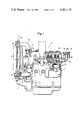
- FIG. 2 is a side view of a water cooled vertical diesel engine, partially in section, showing a second embodiment of the invention
- FIG. 3 is a side view of a water cooled vertical diesel engine, showing a third embodiment of the invention.
- FIG. 1 shows a water cooled vertical diesel engine (E) with plural combustion chambers (1), on whose front part there is mounted a radiator (2), supported on a cushion rubber (3) fixed on a support rack (4) which is stretching out from the lower front of the engine body (5).
- a water-jacket (6) surrounding the combustion chambers (1).
- a cooling water inlet (7) is perforated through the lower front part of the water-jacket (6)
- a cooling water outlet (8) is perforated through the upper front part of the water-jacket (6).
- Above cooling water inlet (7) is communicated with the lower tank (2a) of the radiator (2) with a cooling water inlet pipe (9), and above cooling water outlet (8) communicates with the upper tank (2b) of the radiator (2) through a cooling water outlet pipe (10).
- a cooling water make-up port (11) is attached on the upper side of the upper tank (2b), and this make-up port (11) is closed with a pressure regulating cap (12) connected on it.
- This pressure regulating cap (12) is constructed so as to open and relieve the steam in the upper tank (2b), when the steam pressure became higher than the set pressure of it.
- a steam relief port (13) is perforated through the upper backward part of the water-jacket (6), more concretely through the back end wall (14) of the water-jacket (6) in the cylinder-head (15).
- this steam relief port (13) there is connected from outside a steam exhaust pipe (16), and this pipe (16) is raised vertically forming an L shape, and a pressure regulating cap (17) is connected on the upper end of the steam exhaust pipe (16).
- pressure regulating cap (17) have to be positioned at least higher than the upper surface of the cylinder-head (15).
- the upper end of the steam exhaust pipe (16) is formed enlarged in diameter, and the cap (17) is attached so as to cover the upper open surface of the pipe (16), and this pipe (16) is shut by compressing a valve plate (18) to a valve seat (19) by means of a coil spring (18a).
- This pressure regulating cap (17) is adjusted so as to open, when the steam pressure in the pipe (16) reaches the set pressure, and by this the steam flows into the atmosphere through an overflow pipe (20) whose upper end is connected to the inside of the pressure regulating cap (17).
- This pressure regulating cap (17) is adjusted to open at the nearly equal set pressure as the set pressure for the pressure regulating cap (12) attached on the upper tank (2b).
- the character (21) shows an O-ring inserted between the back wall (14) and the flange (22) of the steam exhaust pipe (16).
- a communicating pipe (23) is connected to the steam relief port (13) at its lower end, and this pipe (23) is raised vertically forming an L shape, until the same elevation with the upper tank (2b), and then runs forward horizontally, and the upper front end of the communicating pipe (23) is connected to the cooling water outlet pipe (10). More particularly, an elbow (10a) forming the lowest part of the cooling water outlet pipe (10) is connected to the cooling water outlet (8) at its lower end, a thermostatic control valve (24) is connected to the upper end of this elbow (10a) at its inlet port.
- a T pipe joint (25) of large diameter is connected to the exhaust port of above thermostatic control valve (24) at its lower end, and the front end of this T pipe joint (25) is connected to the upper tank (2b) of the radiator (2), and the backward end of the T pipe joint (25) is connected to the front end of a short pipe (23c).
- a short pipe 23c
- an elbow (23a) forming the lowest part of it is connected to the steam relief port (13) at its lower end, and a thermostatic control valve (24) is connected to the upper end of this elbow (23a) at its inlet port.
- the mid part of the communicating pipe (23) is formed with an L pipe (23b), and this L pipe (23b) is connected to the exhaust port of the valve (24) at its lower end.
- the backward end of the T pipe joint (25) and the front end of the L pipe (23b) are connected with the short pipe (23c), and a cooling water make-up port (11) is formed at the highest part of this short pipe (23c), and a pressure regulating cap (12) is connected on this make-up port (11).
- An overflow pipe (26) is lead from this pressure regulating cap (12) to the bottom of the engine body (5).
- the pressure regulating cap (12) communicated with the upper tank (2b) and the pressure regulating cap (17) communicated with the steam relief port (13) are combined.
- each thermostatic control valve (24) is adjusted so as to open when the fluid temperature in it is over the set temperature, in order to prevent over heating the combustion chambers (1).
- the cooling water flows from the water-jacket (6) into the upper tank (2b) through the cooling water outlet pipe (10) and the communicating pipe (23), in normal horizontal condition of the engine (E).
- the steam can be guided effectively through the communicating pipe (23) or the cooling water outlet pipe (10).
Landscapes
- Engineering & Computer Science (AREA)
- Chemical & Material Sciences (AREA)
- Combustion & Propulsion (AREA)
- Mechanical Engineering (AREA)
- General Engineering & Computer Science (AREA)
- Cylinder Crankcases Of Internal Combustion Engines (AREA)
Applications Claiming Priority (4)
| Application Number | Priority Date | Filing Date | Title |
|---|---|---|---|
| JP55-24456[U] | 1980-02-26 | ||
| JP2445680U JPS6121546Y2 (de) | 1980-02-26 | 1980-02-26 | |
| JP2445580U JPS6039452Y2 (ja) | 1980-02-26 | 1980-02-26 | 水冷エンジンの燃焼室冷却装置 |
| DE55-24455[U] | 1980-02-26 |
Publications (1)
| Publication Number | Publication Date |
|---|---|
| US4361118A true US4361118A (en) | 1982-11-30 |
Family
ID=26361959
Family Applications (1)
| Application Number | Title | Priority Date | Filing Date |
|---|---|---|---|
| US06/211,675 Expired - Lifetime US4361118A (en) | 1980-02-26 | 1980-12-01 | Cooling apparatus of combustion chambers for water-cooled engines |
Country Status (2)
| Country | Link |
|---|---|
| US (1) | US4361118A (de) |
| AT (1) | AT388778B (de) |
Citations (4)
| Publication number | Priority date | Publication date | Assignee | Title |
|---|---|---|---|---|
| US3820593A (en) * | 1970-12-01 | 1974-06-28 | Daimler Benz Ag | Installation for venting the cooling liquid of an internal compustionengine |
| US3921600A (en) * | 1973-03-22 | 1975-11-25 | Bayerische Motoren Werke Ag | Circulating cooling system for piston internal combustion engines |
| US4182404A (en) * | 1977-12-27 | 1980-01-08 | Fiat-Allis Construction Machinery, Inc. | Radiator top tank with plural sump lines |
| US4200065A (en) * | 1977-05-11 | 1980-04-29 | Maschinenfabrik Augsburg-Nurnberg Aktiengesellschaft | Method for preventing undesirable heat losses in a cooling system for liquid-cooled vehicular internal-combustion engines |
-
1980
- 1980-12-01 US US06/211,675 patent/US4361118A/en not_active Expired - Lifetime
- 1980-12-05 AT AT0596480A patent/AT388778B/de not_active IP Right Cessation
Patent Citations (4)
| Publication number | Priority date | Publication date | Assignee | Title |
|---|---|---|---|---|
| US3820593A (en) * | 1970-12-01 | 1974-06-28 | Daimler Benz Ag | Installation for venting the cooling liquid of an internal compustionengine |
| US3921600A (en) * | 1973-03-22 | 1975-11-25 | Bayerische Motoren Werke Ag | Circulating cooling system for piston internal combustion engines |
| US4200065A (en) * | 1977-05-11 | 1980-04-29 | Maschinenfabrik Augsburg-Nurnberg Aktiengesellschaft | Method for preventing undesirable heat losses in a cooling system for liquid-cooled vehicular internal-combustion engines |
| US4182404A (en) * | 1977-12-27 | 1980-01-08 | Fiat-Allis Construction Machinery, Inc. | Radiator top tank with plural sump lines |
Also Published As
| Publication number | Publication date |
|---|---|
| ATA596480A (de) | 1989-01-15 |
| AT388778B (de) | 1989-08-25 |
Similar Documents
| Publication | Publication Date | Title |
|---|---|---|
| US4964371A (en) | Automobile engine cooling system | |
| CN1160123A (zh) | 内燃机的冷却循环回路 | |
| CN101315042B (zh) | 一种v型发动机及其冷却系统 | |
| EP0580934A1 (de) | Kühlanlage für Kraftwagenbrennkraftmaschine | |
| EP0653554A1 (de) | Thermostat für die Kühlanlage einer Kraftwagenbrennkraftmaschine | |
| KR20200048578A (ko) | 엔진의 냉각장치 | |
| US5970928A (en) | Self restricting engine cooling system deaeration line | |
| US4361118A (en) | Cooling apparatus of combustion chambers for water-cooled engines | |
| US3246637A (en) | Cross flow deaeration engine cooling system | |
| US2443518A (en) | Cooling system for internal-combustion engines | |
| KR20200049982A (ko) | 엔진의 냉각장치 | |
| KR100448737B1 (ko) | 냉각수의 과열시 안전을 위한 2단 제어 방식의 라디에이터캡 장치 | |
| US4972808A (en) | Arrangement of cooling system for transversely mounted internal combustion engine | |
| US4681067A (en) | Liquid-cooled engine of the vertical shaft type | |
| US3163157A (en) | Apparatus for cooling an internal combustion engine | |
| JPH0211724B2 (de) | ||
| EP0134579A1 (de) | Kühlmantelvorrichtung für eine mit siedender Flüssigkeit gekühlten Brennkraftmaschine | |
| JPS6114588Y2 (de) | ||
| JPS6039452Y2 (ja) | 水冷エンジンの燃焼室冷却装置 | |
| JPS55160117A (en) | Circulation controller for cooling water in internal combustion engine with exhaust turbo-charger | |
| JPH0740652Y2 (ja) | 内燃機関の冷却装置 | |
| JP2822707B2 (ja) | V型内燃機関の冷却装置 | |
| JPS59200011A (ja) | エンジン冷却装置 | |
| JPH05256134A (ja) | 水冷式内燃機関の冷却装置 | |
| US1658933A (en) | Process of and apparatus for operating internal-combustion engines |
Legal Events
| Date | Code | Title | Description |
|---|---|---|---|
| AS | Assignment |
Owner name: KUBOTA LTD 47-2 1-CHOME SHIKITSUHIGASHI NANIWAKU O Free format text: ASSIGNMENT OF ASSIGNORS INTEREST.;ASSIGNOR:TOKITA, YOSHIHIRO;REEL/FRAME:004029/0803 Effective date: 19820823 |
|
| STCF | Information on status: patent grant |
Free format text: PATENTED CASE |