US4330044A - Drill bit - Google Patents
Drill bit Download PDFInfo
- Publication number
- US4330044A US4330044A US06/222,062 US22206281A US4330044A US 4330044 A US4330044 A US 4330044A US 22206281 A US22206281 A US 22206281A US 4330044 A US4330044 A US 4330044A
- Authority
- US
- United States
- Prior art keywords
- shank
- bridge
- cutting element
- edge
- set forth
- Prior art date
- Legal status (The legal status is an assumption and is not a legal conclusion. Google has not performed a legal analysis and makes no representation as to the accuracy of the status listed.)
- Expired - Fee Related
Links
Images
Classifications
-
- E—FIXED CONSTRUCTIONS
- E21—EARTH DRILLING; MINING
- E21B—EARTH DRILLING, e.g. DEEP DRILLING; OBTAINING OIL, GAS, WATER, SOLUBLE OR MELTABLE MATERIALS OR A SLURRY OF MINERALS FROM WELLS
- E21B10/00—Drill bits
- E21B10/46—Drill bits characterised by wear resisting parts, e.g. diamond inserts
- E21B10/58—Chisel-type inserts
Definitions
- the invention relates generally to drill bits and more particularly to hollow drill bits having openings at the cutting end for supplying a fluid adjacent to the cutting element or for providing a vacuum adjacent to the cutting element and having a bridge supporting the cutting element.
- Drill bits having openings at the cutting end to provide a fluid or a vacuum adjacent to the cutting element are known and examples of such drill bits are shown in U.S. Pat. Nos. 2,971,409; 3,010,345; 3,415,332; 3,434,553; 3,434,554; 4,099,585; 4,190,125 and 4,190,128. Additionally, the "DUST HOG" drill bit manufactured by Mining Tools Inc. located in Mentor, Ohio has such openings. In some of the above noted prior art drill bits the openings at the cutting end are located in a quadrant equaling approximately one-half the length of the opposite faces of the cutting element. In other prior art bits noted above the openings at the cutting end extend completely along each face of the cutting element. In all of these prior art drill bits the cutting element is brazed or otherwise fixed in place at the end of the bit in opposed slots cut in the end of the shank of the bit.
- Drill bits having openings which extend only part way along the opposite faces of the cutting element the openings are not large enough to provide a sufficient quantity of fluid or a sufficient vacuum adjacent to the cutting element to achieve the desired drilling speed and efficiency.
- Drill bits having openings extending completely along the opposite faces of the cutting elements provide larger openings adjacent to the cutting element, but the cutting element is not adequately supported in the bit shank since it is only supported at its ends by the wall of the shank and there is inadequate backup support for the cutting element during drilling.
- the hollow drill bit of the invention is an improvement over prior art drill bits since it has semicircular openings which extend completely along each face of the cutting element and includes a bridge for supporting the cutting element in the bit shank.
- the bridge is fixed in opposed slots in the end of the shank and provides support for the cutting element along its bottom edge as well as backup support for the portion of each face of the cutting element which lies behind a cutting edge during drilling which is approximately one-half of the surface of each face.
- the bit of the invention has the advantages of a bit with large openings for providing a fluid or a vacuum completely along each face of the cutting element while also providing support for the bottom edge of the cutting element during drilling.
- the portion of the bridge which backs up that portion of each face of the cutting element lying behind a cutting edge prevents fracture of the cutting element by shear forces during drilling and prevents destruction of the cutting element by compression caused by longitudinal forces as the bit is forced into material during drilling.
- longitudinal slots are cut in the shank on opposite sides of the bridge and the cutting element in the portions of the shank which lead the cutting edges of the cutting element during drilling. These slots permit a large amount of fluid to be supplied to the cutting element which results in good chip and dust removal from the cutting element since packing of dust between the faces of the cutting element and the shank is substantially eliminated.
- the end of the shank on both sides of the bridge and the cutting element is formed in the shape of a depressed sine wave with the lower portion of each sine wave located on the portions of the edge of the shank which lead the cutting edges of the cutting element during drilling.
- a primary use of the drill bit of the invention is to drill holes in mine roofs to receive roof bolts and in drilling such holes, the drill bit is mounted on the upper end of a hollow drill steel.
- a hollow drill steel For this purpose an acircular socket having a circular or an acircular cross section is formed on the end of the shank opposite the end carrying the bridge which supports the cutting element.
- One type of attachment arrangement which may be provided between the socket portion of the shank and a drill steel is described in copending application Ser. No. 203,494, filed Nov. 3, 1980.
- An object of the invention is to provide a hollow drill bit having openings for providing a fluid or a vacuum adjacent to the cutting element and to provide a bridge for supporting the cutting element in the shank with good strength during drilling. Another object is to provide a drill bit wherein the contour of the end of the shank adjacent to the cutting element permits good dust and chip removal to increase drilling speed and efficiency.
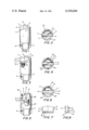
- FIG. 1 is a perspective view of a drill bit according to one embodiment of the invention.
- FIG. 2 is a top view of the drill bit shown in FIG. 1;
- FIG. 3 is a perspective view of a drill bit according to a second embodiment of the invention.
- FIG. 4 is a top view of the drill bit shown in FIG. 3;
- FIG. 5 is a perspective view of a drill bit according to the embodiment of FIG. 3 with the cutting element removed;
- FIG. 6 is a top view of the drill bit shown in FIG. 5;
- FIG. 7 is a side view of the bridge shown in FIGS. 1-6.
- FIG. 8 is an end view of the bridge shown in FIG. 7.
- a drill bit according to the invention has a hollow shank 1 with a socket portion 2 at one end and a bridge 3 which supports a cutting element 4 at the other end.
- the cutting element may be made of tungsten carbide or other suitable material as is well known to those skilled in the art.
- the socket portion 2 may be hexagonal in cross section and is adapted to receive the hexagonal end of a hollow drill steel (not shown). While a hexagonal socket portion is shown, it will be understood by those skilled in the art that other shapes in horizontal cross section may be used so long as the socket portion of the drill bit conforms in cross section with the cross section of a hollow drill steel so that the socket portion will fit over the drill steel.
- a hole 5 is formed in socket portion 2 to receive a pin or spring clip (not shown) which will fit into an opening or a groove in a drill steel to retain the drill bit on the drill steel.
- the edge of the shank adjacent to bridge 3 and cutting element 4 is formed in the shape of flattened or depressed sine wave on both sides of the cutting element.
- the lower portion 6 of each depressed sine wave is located adjacent to an exposed portion of a face of cutting element 4 so that it will be ahead of a cutting edge 7 of cutting element 4 as the bit rotates in order to lead the cutting edge during drilling.
- the upper end of the cutting element is triangular in profile with a central apex 8.
- Cutting element 4 is held in bridge 3 by brazing or by other well known means.
- Each end of bridge 3 is supported in a cutout 9 formed in the end of the shank and the bridge is welded to the shank to hold it in position.
- the bridge is shown in detail in FIGS. 5-8 without a cutting element supported therein and is U-shaped in cross section with a base 10 and upstanding legs 11 and 12.
- Each leg is formed with a center apex which corresponds with the center apex 8 of cutting element 4 when the cutting element is supported in the bridge.
- the upwardly extending legs 11 and 12 slightly embrace opposite faces of the cutting element supported in bridge 3 to impart strength to the cutting element and prevent shear by horizontal forces during drilling. As shown in FIGS.
- each leg of bridge 3 has a right angle cutout 15 which is equal to approximately one-half of the length of the bridge.
- Each cutout 15 is located on the portion of the bridge leg next to that portion of a face of cutting element 4 which has its upper edge exposed to form a cutting edge 7.
- the lower edge 16 of each cutout 15 is formed with a downwardly directed chamfer 17 which assists in the removal of debris during cutting and prevents separation of a face of cutting element 4 and the corresponding leg of the bridge.
- the bottom edge of cutting element 4 abuts the upper surface of base 10 of the bridge to provide vertical support for the cutting element.
- edge of shank 1 is formed with a pair of elongated longitudinal notches 20 and 21 which replace the lower portions 6 of the depressed sine waves at the edge of the shank.
- the elongated longitudinal notches are angularly offset from each other by approximately 180° and are located in the shank ahead of the exposed portions of the cutting element to lead the cutting edges 7 during drilling in order to assist in dust and chip removal.
- the juncture of the edge of shank 1 and the wall of each of notches 20 and 21 is formed with a rounded corner 22 which facilitates the dust and chip removal.
- the bridge and the cutting element mounted therein extend completely across the end of the shank with the ends of both being substantially flush with the outer surface of the shank.
- An opening 25 having a substantially semicircular cross section is formed at the end of shank 1 on each side of bridge 3 and cutting element 4 between the interior surface of the shank and the exterior surfaces of legs 10 and 11 of bridge 3. These semicircular openings permit the supply of a fluid or the creation of a vacuum adjacent to cutting element 4.
- Table I The data set forth in Table I is the result of test conducted in a mine roof consisting of 18 inches of sandstone; a 4 inch clay vein, 12 inches sandstone, a 4 inch clay vein and sandstone for the remainder of the 4 foot holes.
- the sandstone was comprised of 60% quartz. Drilling was carried out with an F.M.C. drilling machine and pressurized water was forced through the drill steel and the hollow bit to wash away the cuttings. The drill was rotated at 90-100 rpm and the boom pressure varied between 700 and 1200 psi. A starter drill steel was used to drill the first 2 feet of each hole and a finish drill steel was used for the remaining 2 feet of each hole where the holes were 4 feet in depth.
- Table II The data set forth hereinafter in Table II is the result of tests conducted in a mine roof consisting of slate with a three to four inch streak of sand rock containing 92% quartz. Drilling was done with an F.M.C. drilling machine and a vacuum was provided at the bit to remove cuttings. A starter drill steel was used to drill the first 2 feet of each hole and a finishing drill steel was used to drill the remaining 2 feet where the holes were 4 feet in depth.
- Table II shows that the bit of FIGS. 1 and 2 of the invention when used with a vacuum at the drill bit will drill 1 foot in an average of 16.6 seconds and the drill bit of FIGS. 3 and 4 of the invention when used with a vacuum will drill 1 foot in an average of 17.2 seconds.
- the Dust Hog bit is used with a vacuum it can drill a 1 foot hole in an average of 26 seconds.
- a substantial improvement is achieved by utilizing a drill bit according to the invention with both water and a vacuum as compared with the Dust Hog bit under the same conditions.
- Drill bits according to the invention have good strength because the bottom edge of the cutting element is supported by the bottom 10 of bridge 3 and the vertical forces opposite cutting edges 7 are backed up by the legs 11 and 12 of bridge 3.
- the semicircular openings 25 adjacent to the bridge and the cutting element permit a fluid or a vacuum to be provided along the full length of the cutting element on both sides thereof which results in rapid and efficient drilling.
- openings extending completely along both faces of the cutting element make it possible to supply a greater quantity of fluid to the cutting edges of the cutting element than in prior art bits which results in rapid removal of dust and swarf and efficient drilling.
- the depressed portions of the edge of the shank permit efficient removal of dust which otherwise tends to become clogged and impacted in the bit.
- the bridge carrying the cutting element makes it less likely that the cutting element will fracture during drilling and, therefore, it is not necessary to replace the drill bit on the drill steel as often as with prior art drill bits.
Abstract
Description
              TABLE I
______________________________________
Hole Depth-Ft.
             Time-Sec. Times Bit Cleaned
______________________________________
1" new bit according to invention (FIGS. 1 and 2) -
pressurized water
4            65        0
4            68        0
4            68        0
2            35        0
2            40        1
2            30        0
2            38        0
2            45        1
2            35        0
2            30        0
2            38        0
2            38        0
2            40        0
2            35        0
2            42        0
2            38        0
2            35        0
Average time to drill 1 foot - 18 sec.
Dust Hog 1" new bit - pressurized water
4            90        2
4            85        2
4            95        3
4            80        2
Average time to drill 1 foot - 21.9 sec.
______________________________________
              TABLE II
______________________________________
Hole Depth-Ft.
             Time-Sec. Times Bit Cleaned
______________________________________
1" reground bit according to the invention
(FIGS. 1 and 2) - vacuum
2            55        1
2            35        0
2            35        0
2            30        0
2            35        0
2            40        0
2            30        0
2            50        1
2            35        0
2            38        0
2            42        0
2            55        1
4            55        0
4            65        1
4            48        0
4            50        0
4            50        0
5            75        1
4            60        0
4            65        0
 Average time to drill 1 foot  16.6 sec.
1" new bit according to the invention
(FIGS. 3 and 4) - vacuum
5            80        1
4            70        1
4            73        0
40           --*       0
 *Roof turned soft  no time recorded
 Average time to drill 1 foot  17.2 sec.
Dust Hog 1" new bit - vacuum
2            62        2
2            65        2
2            55        1
2            55        1
4            75        2
3            --*       --
______________________________________
 *Bit plugged and destroyed
 Average time to drill 1 foot  26 sec.
Claims (15)
Priority Applications (1)
| Application Number | Priority Date | Filing Date | Title |
|---|---|---|---|
| US06/222,062 US4330044A (en) | 1981-01-02 | 1981-01-02 | Drill bit |
Applications Claiming Priority (1)
| Application Number | Priority Date | Filing Date | Title |
|---|---|---|---|
| US06/222,062 US4330044A (en) | 1981-01-02 | 1981-01-02 | Drill bit |
Publications (1)
| Publication Number | Publication Date |
|---|---|
| US4330044A true US4330044A (en) | 1982-05-18 |
Family
ID=22830642
Family Applications (1)
| Application Number | Title | Priority Date | Filing Date |
|---|---|---|---|
| US06/222,062 Expired - Fee Related US4330044A (en) | 1981-01-02 | 1981-01-02 | Drill bit |
Country Status (1)
| Country | Link |
|---|---|
| US (1) | US4330044A (en) |
Cited By (23)
| Publication number | Priority date | Publication date | Assignee | Title |
|---|---|---|---|---|
| US4488609A (en) * | 1982-02-08 | 1984-12-18 | Gte Laboratories, Inc. | Mining drill |
| US4515230A (en) * | 1982-10-25 | 1985-05-07 | Fansteel Inc. | Roof drill bit |
| US4605079A (en) * | 1985-06-20 | 1986-08-12 | The Marmon Group | Drill bit |
| US4627503A (en) * | 1983-08-12 | 1986-12-09 | Megadiamond Industries, Inc. | Multiple layer polycrystalline diamond compact |
| US4688652A (en) * | 1981-03-27 | 1987-08-25 | Kennametal Inc. | Braze fixtures for use in drilling tools |
| US4711312A (en) * | 1986-07-22 | 1987-12-08 | The Marmon Group, Inc. | Drill bit |
| US4817742A (en) * | 1987-08-11 | 1989-04-04 | Kennametal Inc. | Butterfly-type shim having perforations in mid-section thereof and double sandwich braze joint produced therewith |
| US4821819A (en) * | 1987-08-11 | 1989-04-18 | Kennametal Inc. | Annular shim for construction bit having multiple perforations for stress relief |
| US5226489A (en) * | 1992-01-10 | 1993-07-13 | Kennametal Inc. | Insert spacer assembly |
| US5400861A (en) * | 1994-05-05 | 1995-03-28 | Kennametal, Inc. | Rotatable cutting bit assembly |
| US6595305B1 (en) | 2000-02-15 | 2003-07-22 | Kennametal Inc. | Drill bit, hard member, and bit body |
| US20040262045A1 (en) * | 2003-06-30 | 2004-12-30 | Bise Douglas E. | Earth penetrating rotary drill bit with helical ports |
| US20040265080A1 (en) * | 2003-05-20 | 2004-12-30 | Sandvik Ab | Edge-carrying drill, method for the manufacture of the drill, and drilling tool comprising such a drill |
| US20050025594A1 (en) * | 2003-05-20 | 2005-02-03 | Sandvik Ab | Edge-carrying drill body having an internal chip-removal channel |
| US6860344B2 (en) | 2001-06-25 | 2005-03-01 | Kennametal Inc. | Monolithic roof cutting bit insert |
| US20070086867A1 (en) * | 2005-10-13 | 2007-04-19 | The Boeing Company | Vacuum drilling system |
| US20070193784A1 (en) * | 2006-02-20 | 2007-08-23 | Hilti Aktiengesellschaft | Rock drilling head |
| US8584777B2 (en) | 2010-06-04 | 2013-11-19 | Dover Bmcs Acquisition Corporation | Rotational drill bits and drilling apparatuses including the same |
| US9080400B1 (en) | 2010-11-24 | 2015-07-14 | Dover Bmcs Acquisition Corporation | Rotational drill bits and drilling apparatuses including the same |
| US9109412B2 (en) | 2010-06-04 | 2015-08-18 | Dover Bmcs Acquisition Corporation | Rotational drill bits and drilling apparatuses including the same |
| US9194187B2 (en) | 2013-03-15 | 2015-11-24 | Dover Bmcs Acquisition Corporation | Rotational drill bits and drilling apparatuses including the same |
| US9573201B2 (en) | 2013-05-28 | 2017-02-21 | Allied Machine & Engineering Corp. | Vacuum drilling system and methods |
| US20200156163A1 (en) * | 2017-06-27 | 2020-05-21 | Hilti Aktiengesellschaft | Drill for Chiseling Stone |
Citations (15)
| Publication number | Priority date | Publication date | Assignee | Title |
|---|---|---|---|---|
| GB196556A (en) * | 1922-05-30 | 1923-04-26 | Frederick Victor William Swant | Improvements in chisel rock drill tools |
| GB664983A (en) * | 1949-08-24 | 1952-01-16 | Brian Exley Berry | Improvements in and relating to tool tipping |
| GB669636A (en) * | 1947-07-04 | 1952-04-09 | Louis Camille Andre Gardelle | Improvements in or relating to rock drills |
| US2971409A (en) * | 1958-11-17 | 1961-02-14 | Nat Twist Drill & Tool Company | Drill construction |
| US3010345A (en) * | 1958-08-25 | 1961-11-28 | Cleveland Twist Drill Co | Tube drill |
| US3032129A (en) * | 1959-05-01 | 1962-05-01 | J H Fletcher & Co | Dust collecting drill steel and bit |
| US3089552A (en) * | 1961-10-24 | 1963-05-14 | Mine Safety Appliances Co | Rock drill tip holder |
| US3415332A (en) * | 1967-03-08 | 1968-12-10 | Gen Electric | Drill bit |
| US3434554A (en) * | 1967-03-08 | 1969-03-25 | Gen Electric | Cutter bit for drills |
| US3434552A (en) * | 1967-03-08 | 1969-03-25 | Gen Electric | Self-centering cutter bit for drills |
| US3434553A (en) * | 1967-03-08 | 1969-03-25 | Gen Electric | Drill cutter bit |
| US3595327A (en) * | 1969-08-11 | 1971-07-27 | United States Steel Corp | Rotary drill bit and holder |
| US4099585A (en) * | 1977-01-19 | 1978-07-11 | Fansteel Inc. | Roof drilling system |
| US4190128A (en) * | 1978-12-21 | 1980-02-26 | Fansteel Inc. | Roof drill bit with hexagonal body portion |
| US4190125A (en) * | 1977-11-09 | 1980-02-26 | Fansteel Inc. | Drill bit and steel combination for improved fluid flow |
-
1981
- 1981-01-02 US US06/222,062 patent/US4330044A/en not_active Expired - Fee Related
Patent Citations (15)
| Publication number | Priority date | Publication date | Assignee | Title |
|---|---|---|---|---|
| GB196556A (en) * | 1922-05-30 | 1923-04-26 | Frederick Victor William Swant | Improvements in chisel rock drill tools |
| GB669636A (en) * | 1947-07-04 | 1952-04-09 | Louis Camille Andre Gardelle | Improvements in or relating to rock drills |
| GB664983A (en) * | 1949-08-24 | 1952-01-16 | Brian Exley Berry | Improvements in and relating to tool tipping |
| US3010345A (en) * | 1958-08-25 | 1961-11-28 | Cleveland Twist Drill Co | Tube drill |
| US2971409A (en) * | 1958-11-17 | 1961-02-14 | Nat Twist Drill & Tool Company | Drill construction |
| US3032129A (en) * | 1959-05-01 | 1962-05-01 | J H Fletcher & Co | Dust collecting drill steel and bit |
| US3089552A (en) * | 1961-10-24 | 1963-05-14 | Mine Safety Appliances Co | Rock drill tip holder |
| US3415332A (en) * | 1967-03-08 | 1968-12-10 | Gen Electric | Drill bit |
| US3434554A (en) * | 1967-03-08 | 1969-03-25 | Gen Electric | Cutter bit for drills |
| US3434552A (en) * | 1967-03-08 | 1969-03-25 | Gen Electric | Self-centering cutter bit for drills |
| US3434553A (en) * | 1967-03-08 | 1969-03-25 | Gen Electric | Drill cutter bit |
| US3595327A (en) * | 1969-08-11 | 1971-07-27 | United States Steel Corp | Rotary drill bit and holder |
| US4099585A (en) * | 1977-01-19 | 1978-07-11 | Fansteel Inc. | Roof drilling system |
| US4190125A (en) * | 1977-11-09 | 1980-02-26 | Fansteel Inc. | Drill bit and steel combination for improved fluid flow |
| US4190128A (en) * | 1978-12-21 | 1980-02-26 | Fansteel Inc. | Roof drill bit with hexagonal body portion |
Non-Patent Citations (1)
| Title |
|---|
| MTI-Mining Tools Inc. Advertisements re Dust Hog. * |
Cited By (34)
| Publication number | Priority date | Publication date | Assignee | Title |
|---|---|---|---|---|
| US4688652A (en) * | 1981-03-27 | 1987-08-25 | Kennametal Inc. | Braze fixtures for use in drilling tools |
| US4488609A (en) * | 1982-02-08 | 1984-12-18 | Gte Laboratories, Inc. | Mining drill |
| US4515230A (en) * | 1982-10-25 | 1985-05-07 | Fansteel Inc. | Roof drill bit |
| US4627503A (en) * | 1983-08-12 | 1986-12-09 | Megadiamond Industries, Inc. | Multiple layer polycrystalline diamond compact |
| US4605079A (en) * | 1985-06-20 | 1986-08-12 | The Marmon Group | Drill bit |
| US4711312A (en) * | 1986-07-22 | 1987-12-08 | The Marmon Group, Inc. | Drill bit |
| US4817742A (en) * | 1987-08-11 | 1989-04-04 | Kennametal Inc. | Butterfly-type shim having perforations in mid-section thereof and double sandwich braze joint produced therewith |
| US4821819A (en) * | 1987-08-11 | 1989-04-18 | Kennametal Inc. | Annular shim for construction bit having multiple perforations for stress relief |
| US5226489A (en) * | 1992-01-10 | 1993-07-13 | Kennametal Inc. | Insert spacer assembly |
| US5400861A (en) * | 1994-05-05 | 1995-03-28 | Kennametal, Inc. | Rotatable cutting bit assembly |
| US6595305B1 (en) | 2000-02-15 | 2003-07-22 | Kennametal Inc. | Drill bit, hard member, and bit body |
| US6860344B2 (en) | 2001-06-25 | 2005-03-01 | Kennametal Inc. | Monolithic roof cutting bit insert |
| US20040265080A1 (en) * | 2003-05-20 | 2004-12-30 | Sandvik Ab | Edge-carrying drill, method for the manufacture of the drill, and drilling tool comprising such a drill |
| US20050025594A1 (en) * | 2003-05-20 | 2005-02-03 | Sandvik Ab | Edge-carrying drill body having an internal chip-removal channel |
| US7320565B2 (en) * | 2003-05-20 | 2008-01-22 | Sandvik Intellectual Property Ab | Edge-carrying drill, method for the manufacture of the drill, and drilling tool comprising such a drill |
| US7326009B2 (en) * | 2003-05-20 | 2008-02-05 | Sandvik Intellectual Property Ab | Edge-carrying drill body having an internal chip-removal channel |
| US20040262045A1 (en) * | 2003-06-30 | 2004-12-30 | Bise Douglas E. | Earth penetrating rotary drill bit with helical ports |
| US6915867B2 (en) | 2003-06-30 | 2005-07-12 | Kennametal Inc. | Earth penetrating rotary drill bit with helical ports |
| US20070086867A1 (en) * | 2005-10-13 | 2007-04-19 | The Boeing Company | Vacuum drilling system |
| US7563060B2 (en) | 2005-10-13 | 2009-07-21 | The Boeing Company | Vacuum drilling system |
| US20070193784A1 (en) * | 2006-02-20 | 2007-08-23 | Hilti Aktiengesellschaft | Rock drilling head |
| US9371701B2 (en) | 2010-06-04 | 2016-06-21 | Dover Bmcs Acquisition Corporation | Rotational drill bits and drilling apparatuses including the same |
| US8584777B2 (en) | 2010-06-04 | 2013-11-19 | Dover Bmcs Acquisition Corporation | Rotational drill bits and drilling apparatuses including the same |
| US9109412B2 (en) | 2010-06-04 | 2015-08-18 | Dover Bmcs Acquisition Corporation | Rotational drill bits and drilling apparatuses including the same |
| US10100582B2 (en) | 2010-06-04 | 2018-10-16 | Dover Bmcs Acquisition Corporation | Rotational drill bits and drilling apparatuses including the same |
| US9080400B1 (en) | 2010-11-24 | 2015-07-14 | Dover Bmcs Acquisition Corporation | Rotational drill bits and drilling apparatuses including the same |
| US9975210B1 (en) | 2010-11-24 | 2018-05-22 | Dover Bmcs Acquisition Corporation | Rotational drill bits and drilling apparatuses including the same |
| US9951564B1 (en) | 2013-03-15 | 2018-04-24 | Dover Bmcs Acquisition Corporation | Rotational drill bits and drilling apparatuses including the same |
| US9194187B2 (en) | 2013-03-15 | 2015-11-24 | Dover Bmcs Acquisition Corporation | Rotational drill bits and drilling apparatuses including the same |
| US10392866B2 (en) | 2013-03-15 | 2019-08-27 | Apergy Bmcs Acquisition Corporation | Rotational drill bits and apparatuses including the same |
| US9573201B2 (en) | 2013-05-28 | 2017-02-21 | Allied Machine & Engineering Corp. | Vacuum drilling system and methods |
| US10005138B2 (en) | 2013-05-28 | 2018-06-26 | Allied Machine & Engineering Corp. | Vacuum drilling system and methods |
| US20200156163A1 (en) * | 2017-06-27 | 2020-05-21 | Hilti Aktiengesellschaft | Drill for Chiseling Stone |
| US11691204B2 (en) * | 2017-06-27 | 2023-07-04 | Hilti Aktlengesellschaft | Drill for chiseling stone |
Similar Documents
| Publication | Publication Date | Title |
|---|---|---|
| US4330044A (en) | Drill bit | |
| US4527643A (en) | Rotary cutting member for drilling holes | |
| US4836178A (en) | Inset for a tool | |
| US5303787A (en) | Rotary mining tools | |
| US7013812B2 (en) | Tamping tool | |
| US4545441A (en) | Drill bits with polycrystalline diamond cutting elements mounted on serrated supports pressed in drill head | |
| US4073354A (en) | Earth-boring drill bits | |
| US4316636A (en) | Excavation and road maintenance bits and blocks | |
| US20070114835A1 (en) | Flighting and tool holder | |
| US4889200A (en) | Rock drill | |
| US4368789A (en) | Drilling apparatus | |
| US4915182A (en) | Cutter elements for hollow drill bit | |
| US7959234B2 (en) | Rotatable cutting tool with superhard cutting member | |
| US4106578A (en) | Percussion drill bit | |
| WO1997006342A1 (en) | Stabiliser tool | |
| US4261620A (en) | Tapered lock pin for a cutter tool bit | |
| US3918538A (en) | Rotary percussion earth boring bit | |
| US4911729A (en) | Overburden eliminator rock drill bit | |
| PL113333B2 (en) | Bit for mining machines | |
| US4749052A (en) | Cutting element adapted to be pushed into a recess of a drill bit body | |
| GB2177144A (en) | Cutting tool for a mining machine | |
| JP2963698B2 (en) | Hollow drill tools | |
| US5458211A (en) | Spade drill bit construction | |
| US1647753A (en) | Drill cutter | |
| US3862665A (en) | Scrape-type cutter for drill bits |
Legal Events
| Date | Code | Title | Description |
|---|---|---|---|
| MAFP | Maintenance fee payment |
Free format text: PAYMENT OF MAINTENANCE FEE, 4TH YEAR, PL 96-517 (ORIGINAL EVENT CODE: M170); ENTITY STATUS OF PATENT OWNER: LARGE ENTITY Year of fee payment: 4 |
|
| MAFP | Maintenance fee payment |
Free format text: PAYMENT OF MAINTENANCE FEE, 8TH YEAR, PL 96-517 (ORIGINAL EVENT CODE: M171); ENTITY STATUS OF PATENT OWNER: LARGE ENTITY Year of fee payment: 8 |
|
| FEPP | Fee payment procedure |
Free format text: PAYOR NUMBER ASSIGNED (ORIGINAL EVENT CODE: ASPN); ENTITY STATUS OF PATENT OWNER: LARGE ENTITY |
|
| FEPP | Fee payment procedure |
Free format text: MAINTENANCE FEE REMINDER MAILED (ORIGINAL EVENT CODE: REM.); ENTITY STATUS OF PATENT OWNER: LARGE ENTITY |
|
| FEPP | Fee payment procedure |
Free format text: MAINTENANCE FEE REMINDER MAILED (ORIGINAL EVENT CODE: REM.); ENTITY STATUS OF PATENT OWNER: LARGE ENTITY |
|
| LAPS | Lapse for failure to pay maintenance fees | ||
| FP | Lapsed due to failure to pay maintenance fee |
Effective date: 19940515 |
|
| STCH | Information on status: patent discontinuation |
Free format text: PATENT EXPIRED DUE TO NONPAYMENT OF MAINTENANCE FEES UNDER 37 CFR 1.362 |