US4320623A - Fluid-pressure operated boosters for vehicle braking systems - Google Patents
Fluid-pressure operated boosters for vehicle braking systems Download PDFInfo
- Publication number
- US4320623A US4320623A US06/184,140 US18414080A US4320623A US 4320623 A US4320623 A US 4320623A US 18414080 A US18414080 A US 18414080A US 4320623 A US4320623 A US 4320623A
- Authority
- US
- United States
- Prior art keywords
- operating
- servo
- bore
- valve
- housing
- Prior art date
- Legal status (The legal status is an assumption and is not a legal conclusion. Google has not performed a legal analysis and makes no representation as to the accuracy of the status listed.)
- Expired - Lifetime
Links
- 230000005540 biological transmission Effects 0.000 claims abstract description 15
- 239000012530 fluid Substances 0.000 claims description 12
- 238000010276 construction Methods 0.000 claims description 10
- 230000000295 complement effect Effects 0.000 claims description 4
- 230000000712 assembly Effects 0.000 description 1
- 238000000429 assembly Methods 0.000 description 1
- 230000003190 augmentative effect Effects 0.000 description 1
- 230000004323 axial length Effects 0.000 description 1
- 230000006835 compression Effects 0.000 description 1
- 238000007906 compression Methods 0.000 description 1
- 230000004048 modification Effects 0.000 description 1
- 238000012986 modification Methods 0.000 description 1
Images


Classifications
-
- B—PERFORMING OPERATIONS; TRANSPORTING
- B60—VEHICLES IN GENERAL
- B60T—VEHICLE BRAKE CONTROL SYSTEMS OR PARTS THEREOF; BRAKE CONTROL SYSTEMS OR PARTS THEREOF, IN GENERAL; ARRANGEMENT OF BRAKING ELEMENTS ON VEHICLES IN GENERAL; PORTABLE DEVICES FOR PREVENTING UNWANTED MOVEMENT OF VEHICLES; VEHICLE MODIFICATIONS TO FACILITATE COOLING OF BRAKES
- B60T13/00—Transmitting braking action from initiating means to ultimate brake actuator with power assistance or drive; Brake systems incorporating such transmitting means, e.g. air-pressure brake systems
- B60T13/10—Transmitting braking action from initiating means to ultimate brake actuator with power assistance or drive; Brake systems incorporating such transmitting means, e.g. air-pressure brake systems with fluid assistance, drive, or release
- B60T13/12—Transmitting braking action from initiating means to ultimate brake actuator with power assistance or drive; Brake systems incorporating such transmitting means, e.g. air-pressure brake systems with fluid assistance, drive, or release the fluid being liquid
Definitions
- This invention relates to fluid-pressure operated servo-motor assemblies for vehicle braking systems of the kind in which an effort from pedal-operated input member is transmitted to an output member through a movable wall in a housing and, when the servo-motor is operated, the effort is augmented by a fluid-operating pressure applied to the movable wall and controlled by valve means responsive to relative movement between parts of the assembly.
- the movable wall comprises a piston working in a bore in the housing and the pressure is applied to one end of the piston.
- the valve means should be located in a part of the assembly which is stationary, otherwise a moving connection, for example a hose, or seals under hydraulic pressure, will be required.
- valve means in a servo-motor assembly of the kind set forth for a vehicle braking system the valve means is located in a stationary part of the housing, and is operated by an operating assembly comprising an angularly movable rotary operating member, an axially movable transmission member for applying an operating force to the rotary member, and camming means for translating axial movement of the transmission member into angular movement of the rotary member.
- the provision of the operating assembly enables the valve means to be situated at a fixed location without the provision of a lever. This ensures that the travel of the input member and the output member will be the same.
- Axial movement of the transmission member to cause angular movement of the rotary member is opposed by a reaction from a member or part on which the output member acts, for example the piston of an hydraulic master cylinder, so that the reaction provides a signal for operating the valve means and is transmitted to the pedal through the operating assembly.
- the servo-motor assembly can be defined as being "output reactive.”
- the housing comprises axially movable parts which are keyed against relative rotation and the pressure plate forming the transmission member is slidably keyed to the one part of the housing in which the valve means is located and is carried by the other part of the housing, the pressure plate comprising the rotary member being disposed between the transmission member and an abutment at an adjacent end of the said one part, the arrangement being such that axial movement of the housing parts away from each other to urge the pressure plates together causes angular movement of the rotary member to occur.
- the housing is of unitary construction and the input member extends through the movable wall being keyed against rotation with respect to the housing and being provided at its inner end with a pressure face, and the output member is itself rotatable and is provided at the end adjacent to the input member with a thrust receiving face, the balls being located between the ramps which are provided in the adjacent faces so that, as the input member is advanced in an axial direction relative to the output member the movement of which is opposed by a reaction force, the balls ride down into the recesses to cause angular movement of the rotary member.
- valve means comprises a piston working in a radial bore in the housing and of which the innermost end is acted upon by the rotary member to urge the piston relatively outwardly initially to close an outlet port for connection to a reservoir and thereafter to open an inlet port for connection to source of fluid under pressure, which causes such fluid to be applied to the movable wall.
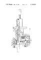
- FIG. 1 is a section on the line 1--1 of a servo-motor assembly illustrated in FIG. 2;
- FIG. 2 is a section of the line 2--2 of FIG. 1;
- FIG. 3 is a section similar to FIG. 2 of a modified servo-motor assembly.
- the servo-motor illustrated in FIGS. 1 and 2 of the accompanying drawings comprises a housing 1 having a main body part 2 and a second body part 3 which is axially movable with respect to the main body part 2 and which provides a mounting for the body 4 of a master cylinder shown in chain-dotted outline.
- the main body part 2 is provided with an open-ended longitudinally extending bore 5 having bore portion 6, 7 and 8 of progressively smaller diameter.
- a stepped boost piston 9 working in the bore portion 7 and 8 is of tubular outline to form a guide for a reaction piston 10 on opposite ends of which act a pedal-operated input member 11 and an output member 12 for operating the master cylinder.
- the bore portion 6 is counterbored at 15 to define an annular chamber disposed between a shoulder 16 at the step in diameter between the bore portion 6 and the counterbore 15 and an inwardly directed annular flange 17 carrying a lip seal 18.
- the body part 3 comprises a cylindrical extension 19 at the inner end of an annular member 20.
- the extension 19 works through the lip seal 18 and at its inner end carries an annular plate 21 which is keyed against rotation with respect to the body part 2.
- a second rotatable annular plate 22 is disposed between the plate 20 and a thrust bearing 23 in abutment with the flange 17, and the plate 22 is provided with a radial valve-operating projection 24 for controlling operation of valve means 25.
- Balls 26 are located between complementary ramps 27 in the plates and normally are at the top of the ramps with the plates spaced apart.
- the valve means 25 control the application of pressure from a servo to a boost chamber 28 which is defined in the bore 5 between a seal 29 through which the smaller diameter portion of the piston 9 works and a seal 30 carried by the greater diameter portion.
- the valve means comprises a piston assembly 31 of differential outline working in a stepped radial bore 32 in the body port 2 with the outer end of greater diameter closed by a plug 33 and a spring 34 urging the piston assembly 31 inwardly into engagement with the projection 24.
- Normally a port 35 for connection to a reservoir for hydraulic fluid is in communication with the boost chamber 28 through a passage 36 and a port 37 for connection to a source of fluid under pressure, for example a pump or hydraulic accumulator, is closed by the portion 39 of the piston assembly 31 which is of greater diameter.
- the servo-pressure in the boost chamber 28 is transmitted to the reaction piston 10 through the head 14 and, in turn, exerts a force on the operating assembly comprising the plates 21 and 22 and the balls 26 substantially equal to the force generated by the reaction from the master cylinder, which in turn is equal to the sum of the force from the input portion 10 and the boost piston 9.
- the pressure in the boost chamber 28 acts, with the assistance of the spring 34, to urge the piston assembly in the opposite direction to close the port 37 and open the port 35. Thereafter the spring 13 acts to return the master cylinder and the rotary plate 22 to their initial positions.
- a by-pass valve for a power-steering pump comprising a spool 40 of differential outline is connected in parallel with the valve means 25 and has a larger diameter portion 41 working in a sealed radial bore 42 which is blind and which is of constant diameter throughout its axial length and a smaller diameter end portion normally engaging with a plug 43 at the open end of the bore 42 through the action of a compression spring 44. That end of the spool 41 is exposed at all times to the pressure source so that, when the servo-motor assembly is inoperative, the spool 41 is urged inwardly to expose a port 45 connected to a steering mechanism so that fluid from the source is supplied thereto.
- the opposite end of the spool 41 is inserted in the passage 36 so that, when the servo-motor assembly is operated, both ends of the spool are subjected to equal pressures so that, because of the loading in the spring 44, the spool is urged outwardly to close the port 45 and provide priority to the booster chamber 28 from the source.
- a member 57 for operating the valve means 25 is located at the inner end of the bore 5 in abutment with the adjacent end of the body 4 of the master cylinder, and the member 57, apart from forming an abutment for the spring 13, is also coupled to the output member 12 through a ball and friction less spline arrangement 58. This allows the output member 12 to move angularly with respect to the piston 10 and axially with respect to the member 57 as the member 57 is moved angularly to operate the valve means.
- FIG. 3 The construction and operation of the embodiment of FIG. 3 is otherwise the same as that of FIGS. 1 and 2 and corresponding reference numerals have been applied to corresponding parts.
- the servo-motor assembly is operated from a supply of hydraulic fluid under pressure
- the servo-motor assembly may equally well be operated pneumatically.
Landscapes
- Engineering & Computer Science (AREA)
- Transportation (AREA)
- Mechanical Engineering (AREA)
- Braking Systems And Boosters (AREA)
- Braking Arrangements (AREA)
- Hydraulic Control Valves For Brake Systems (AREA)
Applications Claiming Priority (2)
| Application Number | Priority Date | Filing Date | Title |
|---|---|---|---|
| GB20988/76A GB1579827A (en) | 1976-05-21 | 1976-05-21 | Fluid-pressure operated boosters for vehicle braking systems |
| GB20988/76 | 1976-05-21 |
Related Parent Applications (1)
| Application Number | Title | Priority Date | Filing Date |
|---|---|---|---|
| US06005786 Continuation | 1979-01-23 |
Publications (1)
| Publication Number | Publication Date |
|---|---|
| US4320623A true US4320623A (en) | 1982-03-23 |
Family
ID=10155271
Family Applications (1)
| Application Number | Title | Priority Date | Filing Date |
|---|---|---|---|
| US06/184,140 Expired - Lifetime US4320623A (en) | 1976-05-21 | 1980-09-04 | Fluid-pressure operated boosters for vehicle braking systems |
Country Status (6)
| Country | Link |
|---|---|
| US (1) | US4320623A (OSRAM) |
| JP (1) | JPS52143379A (OSRAM) |
| DE (1) | DE2722939A1 (OSRAM) |
| ES (1) | ES459012A1 (OSRAM) |
| FR (1) | FR2351833A1 (OSRAM) |
| GB (1) | GB1579827A (OSRAM) |
Cited By (2)
| Publication number | Priority date | Publication date | Assignee | Title |
|---|---|---|---|---|
| US4422293A (en) * | 1981-06-12 | 1983-12-27 | The Bendix Corporation | Closed-center hydraulic servo apparatus |
| US6375279B1 (en) * | 1999-02-02 | 2002-04-23 | Kelsey-Hayes Company | Hydraulic control unit with fluid compensator to accommodate travel of master cylinder piston |
Families Citing this family (2)
| Publication number | Priority date | Publication date | Assignee | Title |
|---|---|---|---|---|
| JPS5599450A (en) * | 1979-01-17 | 1980-07-29 | Nissan Motor Co Ltd | Hydraulic booster |
| JP2008017780A (ja) * | 2006-07-13 | 2008-01-31 | Arimitsu Industry Co Ltd | 消毒液タンクの取付構造 |
Citations (7)
| Publication number | Priority date | Publication date | Assignee | Title |
|---|---|---|---|---|
| US2098666A (en) * | 1932-10-15 | 1937-11-09 | Bendix Aviat Corp | Brake |
| US2229247A (en) * | 1937-05-26 | 1941-01-21 | Magneti Marelli Spa | Control device for hydraulic brakes |
| US2934042A (en) * | 1957-10-22 | 1960-04-26 | Kelsey Hayes Co | Booster mechanism |
| US3319925A (en) * | 1965-09-24 | 1967-05-16 | T V Valve Co Ltd | Valve-actuating device |
| US3664130A (en) * | 1970-11-16 | 1972-05-23 | Bendix Corp | Hydraulic brake pressure limiting device |
| US3989223A (en) * | 1973-12-28 | 1976-11-02 | Exxon Production Research Company | Rotary motion failsafe gate valve actuator |
| US4050434A (en) * | 1974-06-22 | 1977-09-27 | Motoren- Und Turbinen-Union Friedrichshafen Gmbh | Hydraulic servo-motor |
Family Cites Families (2)
| Publication number | Priority date | Publication date | Assignee | Title |
|---|---|---|---|---|
| DE2401661C2 (de) * | 1974-01-15 | 1983-08-11 | Robert Bosch Gmbh, 7000 Stuttgart | Hydraulischer Bremsverstärker |
| US3898914A (en) * | 1974-07-18 | 1975-08-12 | Gen Motors Corp | Hydraulic brake booster assembly |
-
1976
- 1976-05-21 GB GB20988/76A patent/GB1579827A/en not_active Expired
-
1977
- 1977-05-20 ES ES459012A patent/ES459012A1/es not_active Expired
- 1977-05-20 DE DE19772722939 patent/DE2722939A1/de not_active Withdrawn
- 1977-05-20 JP JP5861577A patent/JPS52143379A/ja active Pending
- 1977-05-20 FR FR7715521A patent/FR2351833A1/fr active Granted
-
1980
- 1980-09-04 US US06/184,140 patent/US4320623A/en not_active Expired - Lifetime
Patent Citations (7)
| Publication number | Priority date | Publication date | Assignee | Title |
|---|---|---|---|---|
| US2098666A (en) * | 1932-10-15 | 1937-11-09 | Bendix Aviat Corp | Brake |
| US2229247A (en) * | 1937-05-26 | 1941-01-21 | Magneti Marelli Spa | Control device for hydraulic brakes |
| US2934042A (en) * | 1957-10-22 | 1960-04-26 | Kelsey Hayes Co | Booster mechanism |
| US3319925A (en) * | 1965-09-24 | 1967-05-16 | T V Valve Co Ltd | Valve-actuating device |
| US3664130A (en) * | 1970-11-16 | 1972-05-23 | Bendix Corp | Hydraulic brake pressure limiting device |
| US3989223A (en) * | 1973-12-28 | 1976-11-02 | Exxon Production Research Company | Rotary motion failsafe gate valve actuator |
| US4050434A (en) * | 1974-06-22 | 1977-09-27 | Motoren- Und Turbinen-Union Friedrichshafen Gmbh | Hydraulic servo-motor |
Cited By (2)
| Publication number | Priority date | Publication date | Assignee | Title |
|---|---|---|---|---|
| US4422293A (en) * | 1981-06-12 | 1983-12-27 | The Bendix Corporation | Closed-center hydraulic servo apparatus |
| US6375279B1 (en) * | 1999-02-02 | 2002-04-23 | Kelsey-Hayes Company | Hydraulic control unit with fluid compensator to accommodate travel of master cylinder piston |
Also Published As
| Publication number | Publication date |
|---|---|
| JPS52143379A (en) | 1977-11-29 |
| ES459012A1 (es) | 1978-04-01 |
| DE2722939A1 (de) | 1977-12-01 |
| GB1579827A (en) | 1980-11-26 |
| FR2351833B1 (OSRAM) | 1983-08-19 |
| FR2351833A1 (fr) | 1977-12-16 |
Similar Documents
| Publication | Publication Date | Title |
|---|---|---|
| US4566275A (en) | Hydraulic boosters for vehicle braking systems | |
| US4548037A (en) | Hydraulic power boosters for vehicles braking systems | |
| US4615419A (en) | Torque sensing braking controller for brakes | |
| US4444440A (en) | Hydraulic boosters for vehicle braking systems | |
| US4435960A (en) | Hydraulic power boosters for vehicle hydraulic systems | |
| US4320623A (en) | Fluid-pressure operated boosters for vehicle braking systems | |
| US4241583A (en) | Fluid-pressure operated servo-motor assemblies for vehicle braking systems | |
| US3926092A (en) | Concentric hydraulic brake boost mechanism with system by-pass on piston o.d. | |
| US4159853A (en) | Pressure control unit for a vehicular hydraulic braking system | |
| US4283994A (en) | Power brake unit | |
| US3944293A (en) | Hydraulic brake control assembly | |
| US4463562A (en) | Booster assisted hydraulic master cylinders for vehicle braking systems | |
| US4313302A (en) | Hydraulic power boosters for vehicle braking systems | |
| US4732002A (en) | Servo-assisted master cylinder assemblies | |
| GB2098687A (en) | A twin master cylinder or booster assembly for a vehicle braking system | |
| US5065573A (en) | Hydraulic power booster including backup actuator in addition to lever device, for booster control valve | |
| US3707880A (en) | Hydraulic brake booster with piston return device | |
| US4901626A (en) | Hydraulic power booster | |
| US4087972A (en) | Brake booster with spring type ratio changer | |
| JPS5914381B2 (ja) | ドラムブレ−キのホイ−ル・シリンダ | |
| US4022111A (en) | Valve assemblies for vehicle hydraulic braking systems | |
| US2883970A (en) | Closed system hydraulic motor | |
| US4754604A (en) | Hydraulic brake booster with tubular conduit return spring | |
| JP2522487B2 (ja) | 液圧倍力装置 | |
| US4442671A (en) | Control valve assemblies for two pedal-operated hydraulic braking systems |
Legal Events
| Date | Code | Title | Description |
|---|---|---|---|
| AS | Assignment |
Owner name: GIRLING LIMITED, KINGS RD., TYSELEY, BIRMINGHAM, 1 Free format text: ASSIGNMENT OF ASSIGNORS INTEREST.;ASSIGNOR:FARR, GLYN P. R.;REEL/FRAME:003938/0469 Effective date: 19770503 |
|
| STCF | Information on status: patent grant |
Free format text: PATENTED CASE |