US4296992A - Electrical connector assembly - Google Patents
Electrical connector assembly Download PDFInfo
- Publication number
- US4296992A US4296992A US06/028,156 US2815679A US4296992A US 4296992 A US4296992 A US 4296992A US 2815679 A US2815679 A US 2815679A US 4296992 A US4296992 A US 4296992A
- Authority
- US
- United States
- Prior art keywords
- shell
- ring
- insert member
- connector assembly
- retaining ring
- Prior art date
- Legal status (The legal status is an assumption and is not a legal conclusion. Google has not performed a legal analysis and makes no representation as to the accuracy of the status listed.)
- Expired - Lifetime
Links
Images




Classifications
-
- H—ELECTRICITY
- H01—ELECTRIC ELEMENTS
- H01R—ELECTRICALLY-CONDUCTIVE CONNECTIONS; STRUCTURAL ASSOCIATIONS OF A PLURALITY OF MUTUALLY-INSULATED ELECTRICAL CONNECTING ELEMENTS; COUPLING DEVICES; CURRENT COLLECTORS
- H01R13/00—Details of coupling devices of the kinds covered by groups H01R12/70 or H01R24/00 - H01R33/00
- H01R13/62—Means for facilitating engagement or disengagement of coupling parts or for holding them in engagement
- H01R13/622—Screw-ring or screw-casing
-
- H—ELECTRICITY
- H01—ELECTRIC ELEMENTS
- H01R—ELECTRICALLY-CONDUCTIVE CONNECTIONS; STRUCTURAL ASSOCIATIONS OF A PLURALITY OF MUTUALLY-INSULATED ELECTRICAL CONNECTING ELEMENTS; COUPLING DEVICES; CURRENT COLLECTORS
- H01R13/00—Details of coupling devices of the kinds covered by groups H01R12/70 or H01R24/00 - H01R33/00
- H01R13/46—Bases; Cases
- H01R13/502—Bases; Cases composed of different pieces
- H01R13/508—Bases; Cases composed of different pieces assembled by a separate clip or spring
Definitions
- the present invention relates generally to electrical connectors and, more particularly, to electrical connector assemblies in which an elastomeric insert member is mounted within a generally rigid shell or housing and in which the insert member may be assembled to or disassembled from the shell very quickly and easily while still providing a rugged construction which is also relatively tamper proof.
- the present connector assembly in which an elastomeric molded connector insert is locked within a rigid shell.
- the rigid shell which protects the insert from mechanical abuse and environmental conditions is adapted for mounting to panels or to other supporting surfaces.
- the molded insert is easily and firmly fixed within the shell by means of a retaining ring which engages both the insert and the shell. Engagement of the ring with the shell is accomplished by radially movable retention means.
- the retaining ring produces a tight, tamper proof interengagement between the shell and the insert which nevertheless may be readily released with a simple tool which is inserted through a passageway provided in the connector assembly.
- the retaining ring is made of two half ring sections joined by a living hinge.
- the half ring sections from an annular element in which the ring sections are held in place by the cooperation of the outer shell and the inner elastomeric connector.
- the preferred retaining ring may be adapted to be retrofitted to standard elastomeric molded connectors or inserts or it may be fitted to specially modified elastomeric molded inserts.
- the present invention is directed to a connector assembly comprising a shell and elastomeric insert member for supporting at least one electrical contact and a retaining ring.
- the connector assembly includes, in addition to the shell insert and ring, a passageway permitting disengagement of the assembly.
- the retaining ring includes a first retention means for engaging and maintaining the insert member in fixed position within the ring.
- the retaining ring also includes a radially movable second retention means for engaging the shell to maintain the ring and insert member in fixed axially position within the shell.
- the assembly may be easily dismantled by insertion of a simple tool through a passageway which provides access to the second retention means, thereby permitting disengagement of the ring and insert member from the shell.
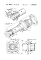
- FIG. 1 is a side elevational view, partially in section, of a connector assembly incorporating the principles of the present invention
- FIG. 2 is an end elevation view of a connector assembly taken along line 2--2 of FIG. 1;
- FIG. 3 is an elevational view of the retaining ring of the connector assembly of FIG. 1 wherein the ring is opened about its hinge;
- FIGS. 4, 5 and 6 are views of the ring of FIG. 3 taken along line 4--4, 5--5, and 6--6, respectively;
- FIG. 7 is a perspective view of an elastomeric connector insert resting in one half of an opened retaining ring
- FIG. 8 is an exploded perspective view of a connector assembly including, in addition to the insert and retaining ring assembly depicted in FIG. 7, a shell adapted for mounting in a panel aperture or other support surface by means of a threaded panel nut;
- FIG. 9 is a side elevational view of a connector assembly wherein the rigid shell is adapted for mounting to a panel by means of a self threading hexscrews which engage holes in the shell flange;
- FIG. 10 is an end view of the mounted connector assembly taken along lines 10--10 of FIG. 9;
- FIG. 11 is a perspective view of a specifically configured elastomeric connector insert resting in one half of an opened retaining ring and including conductors communicating with contacts within the insert;
- FIG. 12 is an exploded perspective view of a connector assembly designed to be assembled to a threaded coupling containing a mating connector in which the connector insert and retaining ring assembly of FIG. 11 cooperates with a coupling nut and rigid shell;
- FIG. 13 is a partial sectional view of the assembly of FIG. 12 joined to a threaded coupling containing a complementary mating connector also fitted with a rigid shell and retaining ring.
- a connector assembly 10 comprising a shell 12, an elastomeric moldable connector or insert member 14 and a retaining ring 16.
- the shell 12 which is made of a rigid material such as metal or preferably a plastic, is best illustrated in FIGS. 1, 2, 8, 9 and 10.
- the shell 12 includes a flange 18 designed to abut a panel or other support surface 19 and means for affixing the shell to the panel by drawing the flange against the panel surface.
- Conventional fastening means can be used for this purpose such as the threaded portion 20 and mating panel nut 22, as illustrating in FIGS. 1 & 8, or a flange with predrilled holes 24 engaged by selfthreading screws 26 which pass through the panel from the side opposite the flange and draw the flange up against the panel as they are tightened, as illustrated in FIGS. 9 and 10.
- the shell 12 also includes a keyway 27 designed for engaging a key 58 on the ring 16 in order to prevent rotation of the ring and connector 14 within the shell 12.
- the shell 12 is provided with an internal annular camming surface C disposed on the inside surface of the shell. As will be discussed further below in connection with the description of the retaining ring 16, this camming surface C is engaged by the radially movable second retention means 46 of the retaining ring as the subassembly D of ring 16 and connector 14 is brought into engagement with the shell 12.
- the elastomeric molded connector or insert 14 may be of a conventionally available type such as that described in U.S. Pat. No. 3,940,705 and as best depicted in FIG. 7.
- the elastomeric connector 14 includes a round base 28 and an annular sleeve 30. Disposed along the round base 28 is an annular collar 34 defining a front shoulder 32 toward its forward or mating end.
- the retaining ring 16 comprises two half sections 36 joined by a living hinge 38 which permits the half sections to be pivoted to a closed position to form a tubular or annular component.
- the faces B and B' of the half sections 36 are respectively provided with a projection 40 and a corresponding notch 42 for aligning the half sections when they are brought into abutment to form relatively smooth, continuous inner and outer ring surfaces.
- the retaining ring 16 is made up of an annular base 44 and second retention means comprising flexible axially extending arms 46.
- First retention means comprising protuberances or points 50 are disposed on the inner face of the annular base 44, extending radially inward therefrom when the ring half sections 36 are in their closed position. These protuberances 50 grip the insert member 14 in fixed position within the retaining ring 16 within the subassembly D.
- the flexible, axially extending arms 46 of the retaining ring 16 have lips 52 protruding from both the inner and outer surfaces of the distal end of each of the arms, as best illustrated in FIG. 1.
- the lip portions 53 extending radially inward engage the shoulder 32 of the connector 14.
- the lip portions 55 extending radially outwardly engage the shell shoulder C.
- the axially extending arms 46 include a cam surface 54 aligned with the passageway 56 which cooperates with a removal tool (not shown) to disengage the subassembly D of ring 16 and insert member 14 from the shell 12.
- a removal tool not shown
- the connector assembly is put together by first forming the subassembly D comprising connector 16 and retaining ring 14, and then interconnecting the subassembly D to the shell 12.
- the subassembly D is formed by positioning an elastomeric moldable connector 14 within an open retaining ring 16 so that lip portions 55 are aligned with connector shoulder 32.
- the retaining ring half sections 36 are then closed about the connector 14 to form the subassembly D and then manually held in this position while subassembly D is inserted into the shell 12.
- the flexible arms 46 and lips 52 are forced radially inwardly by the action of the shell camming surface C against the lip portion 55 so that the face 57 of the lip portion 53 is first moved into positive contact with the collar 34 and then continues to move radially inward compressing the elastomeric material of the connector base 28.
- the lip portion 53 clears the camming surface C
- the combined action of the compressed portion of the elastomeric connector base 28 and the flexible arms 46 will "spring" the lip 52 into position at the shoulder C' of the camming surface C to produce a distinct "snap-in” effect.
- the lip 52 backed up by the spring action of the elastomeric body of the connector collar 34 will firmly engage the shell 12 and connector 14 thereby forming a tamperproof connector assembly
- a passageway 56 is defined between the outer surface of the sleeve 30 of the connector insert 14 and the corresponding inner surface of the shell 12.
- the passageway 56 is a tubular opening with a diameter and cross-sectional area adapted to permit access to the cam surface 54 of the arms 46.
- a simple tool comprising, for example, a rigid tube of the appropriate diameter and wall thickness, may be inserted into the connector assembly through the passageway 56 so that it engages the cam surfaces 54 and comes to rest against shoulder C' of camming surface C.
- the rigid tube thereby forces the lips 52 into the elastomeric material of the collar 34 and permits the subassembly D to be removed from the shell 12 without interference between the shoulder C' of the cam surface C and the lips 46.
- the connector assembly may optionally include a resilient gasket such as O-ring 68 to seal the passageway 56 thereby preventing fluids from passing through the shell and enhancing the environmental security of the overall assembly.
- An additional resilient gasket such as O-ring 70 of FIG. 1 may be interposed between the flange 18 of the shell 12 and the panel 19 to which it is attached.
- FIGS. 11, 12 and 13 illustrate an alternate embodiment of the invention in which a specially molded elastomeric connector is utilized in lieu of the standard connector 14 of FIGS. 1-10.
- the distinguishing aspects of the second embodiment of FIGS. 11, 12 and 13 will be discussed below.
- FIG. 12 there is illustrated a tubular shell 72 made of a rigid material such as metal or plastic having a forward portion 74 carrying shell polarizing keys 76.
- the shell 72 has a rear portion 78 with an annular rearwardly directed antidecoupling ratchet 80 and a retainer keyway 82.
- the shell 72 has a retaining shoulder 84 annularly positioned on its inner surface.
- the shell 72 cooperates with a tubular coupling nut 86, which is also preferably formed from thermoplastic material.
- the coupling nut 86 has a forwardly directed annular anti-decoupling ratchet shoulder 87 which engages the rearwardly facing antidecoupling ratchet 80 of the shell 72.
- the coupling nut 86 also has threads 90 on its inner surface for engaging a threaded coupling and longitudinal outer ribs 88 as shown in FIG. 12 for improved gripping during tightening or loosening of the coupling nut.
- a specially molded connector insert 98 having an integrally formed insert polarizing key 100 is depicted most clearly in FIG. 11.
- the insert 98 is also formed with a special shell seal 118 constituting a radially extending integral sealing rib on the surface of the connector base 28. This annular rib engages the inner wall of the shell 72 to form an environmentally secure seal generally equivalent to that obtained with the O-ring 68 of the prior embodiment.
- the retaining ring 102 utilized in the embodiment of FIGS. 11-13 again comprises two half sections 104 joined at one pair of corresponding faces E and E' by a living hinge 38.
- the two half sections 104 are dimensioned to close about the connector 98 with the non-hinged corresponding faces F and F' abuting the insert polarizing key 100.
- the cooperation of the insert polarizing key 100 of the insert 98 with the faces F and F' of the half sections 104 of the retaining ring 102 prevents rotation of the insert 98 relative to the retaining ring 102.
- the need for the protuberances or points 50 of the retaining ring 16 of the embodiment of FIGS. 1-10 is eliminated and the insert 98 is polarized relative to the ring.
- the half sections include radially extending retainer key portions 110 which abut the insert polarizing key 100 when the retaining ring 102 is closed about the insert 98. These retainer key portions are configured to be mateable with the retainer keyway 82 of the shell 72.
- the insert 98 is keyed to the ring 102 by way of the cooperation between the insert polarizing key 100 of the insert 98 and the half sections 104 of the retaining ring and this assembly in turn is keyed to the receptacle shell by way of the cooperation between the retainer key portions 110 of the retaining ring 102 and the keyway 82 of the shell 72.
- the mutual cooperation of insert key, retainer key portions and shell keyway makes possible a predetermined and repeatable polarity of connection required in the utilization of multi-contact connectors.
- the retaining ring 102 be closed about the insert 98 and manually held in that position to form first subassembly F.
- the coupling nut 86 and shell 72 are next fitted to the first subassembly so that the retainer key portions 110 mate with the retainer keyway 82 and the ratchet 80 of the shell 72 is spaced-apart from the ratchet shoulder 87 of the coupling nut 86 thereby forming an assembly G'.
- the assembly G' is then connected to the threaded coupling 94 with the assembly G' positioned so that the shell polarizing keys 76 mate with keyways of the threaded coupling 94 as the coupling nut 86 is threaded onto the threaded coupling 94. It should be noted that the cooperation of the shell polarizing keys 76 with the keyways of the threaded coupling makes it possible to maintain the connector 98 in the desired predetermined polarity.
- the threaded coupling 94 carries a second elastomeric moldable insert 112 for mating with the insert 98 which together form an environmentally secure seal along the seal portion 114.
- the second insert 112 is mounted within the threaded coupling using a connector assembly again following the teaching of the present invention.
- the pin and socket contacts 116 and 120 respectively of the cooperating inserts may be disposed in either connector as required.
Landscapes
- Connector Housings Or Holding Contact Members (AREA)
- Details Of Connecting Devices For Male And Female Coupling (AREA)
Priority Applications (7)
| Application Number | Priority Date | Filing Date | Title |
|---|---|---|---|
| US06/028,156 US4296992A (en) | 1977-09-26 | 1979-04-09 | Electrical connector assembly |
| GB8010319A GB2047985B (en) | 1979-04-09 | 1980-03-27 | Electric connector assembly |
| ZA00801890A ZA801890B (en) | 1979-04-09 | 1980-03-31 | Electrical connector assembly |
| DE19803012733 DE3012733A1 (de) | 1979-04-09 | 1980-04-01 | Elektrischer verbinder |
| JP4527880A JPS55157879A (en) | 1979-04-09 | 1980-04-08 | Connector |
| CA000349506A CA1139857A (en) | 1979-04-09 | 1980-04-08 | Electrical connector assembly |
| FR8008237A FR2454196A1 (fr) | 1979-04-09 | 1980-04-09 | Connecteur electrique a organe isolant en elastomere interieur et coquille rigide exterieure |
Applications Claiming Priority (2)
| Application Number | Priority Date | Filing Date | Title |
|---|---|---|---|
| US05/836,325 US4154496A (en) | 1977-09-26 | 1977-09-26 | Coupling assembly for resilient electrical connector components |
| US06/028,156 US4296992A (en) | 1977-09-26 | 1979-04-09 | Electrical connector assembly |
Related Parent Applications (1)
| Application Number | Title | Priority Date | Filing Date |
|---|---|---|---|
| US05/836,325 Continuation-In-Part US4154496A (en) | 1977-09-26 | 1977-09-26 | Coupling assembly for resilient electrical connector components |
Publications (1)
| Publication Number | Publication Date |
|---|---|
| US4296992A true US4296992A (en) | 1981-10-27 |
Family
ID=21841880
Family Applications (1)
| Application Number | Title | Priority Date | Filing Date |
|---|---|---|---|
| US06/028,156 Expired - Lifetime US4296992A (en) | 1977-09-26 | 1979-04-09 | Electrical connector assembly |
Country Status (7)
| Country | Link |
|---|---|
| US (1) | US4296992A (enExample) |
| JP (1) | JPS55157879A (enExample) |
| CA (1) | CA1139857A (enExample) |
| DE (1) | DE3012733A1 (enExample) |
| FR (1) | FR2454196A1 (enExample) |
| GB (1) | GB2047985B (enExample) |
| ZA (1) | ZA801890B (enExample) |
Cited By (11)
| Publication number | Priority date | Publication date | Assignee | Title |
|---|---|---|---|---|
| US4713024A (en) * | 1985-07-30 | 1987-12-15 | Uro Denshi Kogyo Kabushiki Kaisha | Connector for television distribution equipment |
| USD329042S (en) | 1989-05-05 | 1992-09-01 | Sensor Nederland B.V. | Electrical connector housing |
| US5295866A (en) * | 1990-10-09 | 1994-03-22 | Kroger Roy E | Insert retention gas tight seal for electrical connector and method of making same |
| US6634897B2 (en) | 2001-06-26 | 2003-10-21 | Delphi Technologies, Inc. | Twist-lock connector |
| EP1434317A1 (en) * | 2002-12-24 | 2004-06-30 | Japan Aviation Electronics Industry, Limited | Connector and mating connector and combination thereof |
| US20050090153A1 (en) * | 2003-10-28 | 2005-04-28 | Christian Brochu | Bathing unit controller and connector system therefore |
| US20050233639A1 (en) * | 2002-10-04 | 2005-10-20 | Wieland Electric Gmbh | Electrical plug-in connector |
| US20080124030A1 (en) * | 2006-11-29 | 2008-05-29 | Jarrod Scadden | Hybrid fiber/copper connector system and method |
| US20090269011A1 (en) * | 2007-11-30 | 2009-10-29 | Jarrod Scadden | Hybrid fiber/copper connector system and method |
| CN101568869B (zh) * | 2006-11-29 | 2011-07-06 | Adc电信公司 | 混合光纤/铜连接器系统和方法 |
| US20120282793A1 (en) * | 2009-12-23 | 2012-11-08 | Oase Gmbh | Plug Connection Assembly for a Moisture-Protected Electrical Plug Connection |
Families Citing this family (6)
| Publication number | Priority date | Publication date | Assignee | Title |
|---|---|---|---|---|
| US4756640A (en) * | 1983-08-19 | 1988-07-12 | Gkn Automotive Components Inc. | Axial retaining member |
| DE3524137A1 (de) * | 1985-07-05 | 1987-01-15 | Thyssen Plastik Anger Kg | Steckverbindung |
| DE9003016U1 (de) * | 1990-03-12 | 1991-07-11 | Grote & Hartmann Gmbh & Co Kg, 5600 Wuppertal | Steckerkupplung für eine elektrische Steckerverbindung zur Durchkontaktierung einer Wand, insbesondere einer Karosseriewand eines Kraftfahrzeugs |
| DE9010199U1 (de) * | 1990-07-05 | 1990-09-06 | Schaltbau GmbH, 81677 München | Stecker für einen Einschubsteckverbindersatz |
| FR2770041B1 (fr) * | 1997-10-22 | 2000-01-07 | Aerospatiale | Raccord arriere amovible pour un connecteur tel qu'un connecteur electrique circulaire |
| FR2911727B1 (fr) * | 2007-01-22 | 2011-03-25 | Souriau | Connecteur disposant d'une barriere d'etancheite et procede de fabrication d'un tel connecteur. |
Citations (14)
| Publication number | Priority date | Publication date | Assignee | Title |
|---|---|---|---|---|
| US3097905A (en) * | 1961-02-16 | 1963-07-16 | Pyle National Co | Indexable key connector |
| US3588150A (en) * | 1969-07-18 | 1971-06-28 | Raychem Corp | Attaching device for convoluted tubing |
| US3646502A (en) * | 1970-08-24 | 1972-02-29 | Bunker Ramo | Connector element and method for element assembly |
| US3732527A (en) * | 1971-05-04 | 1973-05-08 | T Mcknight | Strain relief clamp |
| US3816641A (en) * | 1973-05-14 | 1974-06-11 | Viking Industries | Underwater connector and method of making same |
| US3855566A (en) * | 1971-09-03 | 1974-12-17 | Shell Oil Co | Hermaphroditic connector for seismic cables |
| US3930705A (en) * | 1974-03-08 | 1976-01-06 | Bunker Ramo Corporation | Electrical connector assembly |
| US4007953A (en) * | 1975-09-10 | 1977-02-15 | International Telephone And Telegraph Corporation | Removable captive coupling nut assembly |
| US4033535A (en) * | 1973-05-18 | 1977-07-05 | Eaton Corporation | Strain-relief bushing |
| US4037909A (en) * | 1976-06-09 | 1977-07-26 | Trompeter Electronics, Inc. | Coaxial cable connector with energy loss prevention |
| US4068911A (en) * | 1976-03-31 | 1978-01-17 | Kings Electronics Company, Inc. | Washer and connector assembly |
| GB1500102A (en) | 1976-01-15 | 1978-02-08 | Itt | Connector member and extraction tool |
| US4074927A (en) * | 1976-07-26 | 1978-02-21 | Automation Industries, Inc. | Electrical connector with insert member retaining means |
| US4154496A (en) * | 1977-09-26 | 1979-05-15 | Bunker Ramo Corporation | Coupling assembly for resilient electrical connector components |
-
1979
- 1979-04-09 US US06/028,156 patent/US4296992A/en not_active Expired - Lifetime
-
1980
- 1980-03-27 GB GB8010319A patent/GB2047985B/en not_active Expired
- 1980-03-31 ZA ZA00801890A patent/ZA801890B/xx unknown
- 1980-04-01 DE DE19803012733 patent/DE3012733A1/de not_active Withdrawn
- 1980-04-08 CA CA000349506A patent/CA1139857A/en not_active Expired
- 1980-04-08 JP JP4527880A patent/JPS55157879A/ja active Pending
- 1980-04-09 FR FR8008237A patent/FR2454196A1/fr active Granted
Patent Citations (14)
| Publication number | Priority date | Publication date | Assignee | Title |
|---|---|---|---|---|
| US3097905A (en) * | 1961-02-16 | 1963-07-16 | Pyle National Co | Indexable key connector |
| US3588150A (en) * | 1969-07-18 | 1971-06-28 | Raychem Corp | Attaching device for convoluted tubing |
| US3646502A (en) * | 1970-08-24 | 1972-02-29 | Bunker Ramo | Connector element and method for element assembly |
| US3732527A (en) * | 1971-05-04 | 1973-05-08 | T Mcknight | Strain relief clamp |
| US3855566A (en) * | 1971-09-03 | 1974-12-17 | Shell Oil Co | Hermaphroditic connector for seismic cables |
| US3816641A (en) * | 1973-05-14 | 1974-06-11 | Viking Industries | Underwater connector and method of making same |
| US4033535A (en) * | 1973-05-18 | 1977-07-05 | Eaton Corporation | Strain-relief bushing |
| US3930705A (en) * | 1974-03-08 | 1976-01-06 | Bunker Ramo Corporation | Electrical connector assembly |
| US4007953A (en) * | 1975-09-10 | 1977-02-15 | International Telephone And Telegraph Corporation | Removable captive coupling nut assembly |
| GB1500102A (en) | 1976-01-15 | 1978-02-08 | Itt | Connector member and extraction tool |
| US4068911A (en) * | 1976-03-31 | 1978-01-17 | Kings Electronics Company, Inc. | Washer and connector assembly |
| US4037909A (en) * | 1976-06-09 | 1977-07-26 | Trompeter Electronics, Inc. | Coaxial cable connector with energy loss prevention |
| US4074927A (en) * | 1976-07-26 | 1978-02-21 | Automation Industries, Inc. | Electrical connector with insert member retaining means |
| US4154496A (en) * | 1977-09-26 | 1979-05-15 | Bunker Ramo Corporation | Coupling assembly for resilient electrical connector components |
Cited By (22)
| Publication number | Priority date | Publication date | Assignee | Title |
|---|---|---|---|---|
| US4713024A (en) * | 1985-07-30 | 1987-12-15 | Uro Denshi Kogyo Kabushiki Kaisha | Connector for television distribution equipment |
| USD329042S (en) | 1989-05-05 | 1992-09-01 | Sensor Nederland B.V. | Electrical connector housing |
| US5295866A (en) * | 1990-10-09 | 1994-03-22 | Kroger Roy E | Insert retention gas tight seal for electrical connector and method of making same |
| US6634897B2 (en) | 2001-06-26 | 2003-10-21 | Delphi Technologies, Inc. | Twist-lock connector |
| US20050233639A1 (en) * | 2002-10-04 | 2005-10-20 | Wieland Electric Gmbh | Electrical plug-in connector |
| US20040132329A1 (en) * | 2002-12-24 | 2004-07-08 | Toshio Shimoyama | Connector and mating connector and combination thereof |
| US6942516B2 (en) | 2002-12-24 | 2005-09-13 | Japan Aviation Electronics Industry Limited | Connector and mating connector and combination thereof |
| EP1434317A1 (en) * | 2002-12-24 | 2004-06-30 | Japan Aviation Electronics Industry, Limited | Connector and mating connector and combination thereof |
| US7419406B2 (en) | 2003-10-28 | 2008-09-02 | Gecko Alliance Group Inc. | Bathing unit controller |
| US20050151425A1 (en) * | 2003-10-28 | 2005-07-14 | 9090-3493 Quebec Inc. | Bathing unit controller |
| US6929516B2 (en) | 2003-10-28 | 2005-08-16 | 9090-3493 Québec Inc. | Bathing unit controller and connector system therefore |
| US20050090153A1 (en) * | 2003-10-28 | 2005-04-28 | Christian Brochu | Bathing unit controller and connector system therefore |
| US20090238519A1 (en) * | 2006-11-29 | 2009-09-24 | Adc Telecommunication, Inc. | Hybrid fiber/copper connector system and method |
| US7490994B2 (en) * | 2006-11-29 | 2009-02-17 | Adc Telecommunications, Inc. | Hybrid fiber/copper connector system and method |
| US20080124030A1 (en) * | 2006-11-29 | 2008-05-29 | Jarrod Scadden | Hybrid fiber/copper connector system and method |
| CN101568869B (zh) * | 2006-11-29 | 2011-07-06 | Adc电信公司 | 混合光纤/铜连接器系统和方法 |
| US8113720B2 (en) | 2006-11-29 | 2012-02-14 | Adc Telecommunications, Inc. | Hybrid fiber/copper connector system and method |
| US20090269011A1 (en) * | 2007-11-30 | 2009-10-29 | Jarrod Scadden | Hybrid fiber/copper connector system and method |
| US8083416B2 (en) | 2007-11-30 | 2011-12-27 | Adc Telecommunications, Inc. | Hybrid fiber/copper connector system and method |
| US8678666B2 (en) | 2007-11-30 | 2014-03-25 | Adc Telecommunications, Inc. | Hybrid fiber/copper connector system and method |
| US20120282793A1 (en) * | 2009-12-23 | 2012-11-08 | Oase Gmbh | Plug Connection Assembly for a Moisture-Protected Electrical Plug Connection |
| US8747138B2 (en) * | 2009-12-23 | 2014-06-10 | Oase Gmbh | Plug connection assembly for a moisture-protected electrical plug connection |
Also Published As
| Publication number | Publication date |
|---|---|
| GB2047985A (en) | 1980-12-03 |
| ZA801890B (en) | 1981-04-29 |
| JPS55157879A (en) | 1980-12-08 |
| CA1139857A (en) | 1983-01-18 |
| FR2454196B1 (enExample) | 1984-06-01 |
| FR2454196A1 (fr) | 1980-11-07 |
| DE3012733A1 (de) | 1980-10-30 |
| GB2047985B (en) | 1983-01-12 |
Similar Documents
| Publication | Publication Date | Title |
|---|---|---|
| US5735704A (en) | Shroud seal for shrouded electrical connector | |
| GB2047985A (en) | Electric connector assembly | |
| US7186127B2 (en) | Nut seal assembly for coaxial connector | |
| US4193655A (en) | Field repairable connector assembly | |
| US9716338B2 (en) | Waterproof separable swivel connector | |
| US4738636A (en) | Strain relief connectors for flexible cord and cable | |
| US6083040A (en) | Connector with releasable mounting flange | |
| US20050176296A1 (en) | Nut seal assembly for coaxial cable system components | |
| US5113571A (en) | Method of manufacturing a connector for medical devices | |
| US4447103A (en) | Moisture seal for a separable electrical connection | |
| US5993266A (en) | Keying system for electrical connector | |
| US7267570B2 (en) | Double beam latch connector | |
| JPH04215272A (ja) | 流体シールを備えたコネクタ | |
| MXPA01007373A (es) | Clavija para conexion electrica. | |
| US3792415A (en) | Weatherproof cover for electrical cable connector | |
| US10401577B2 (en) | Multi-core optical fiber connection device | |
| EP0464559B1 (en) | Sealing device for panel mounted electrical connector | |
| JPS6122427B2 (enExample) | ||
| US4542952A (en) | Electrical connector assembly having locking means | |
| US4857007A (en) | Molded environmental seal for electrical connection | |
| US5795176A (en) | Method of protecting an electrical connection and plug lock therefor | |
| US5434360A (en) | Closure plug for electrical enclosure | |
| JP2986522B2 (ja) | フレキシブル管用継手 | |
| KR900009954Y1 (ko) | 가스호스 연결구조 | |
| JPH039264Y2 (enExample) |
Legal Events
| Date | Code | Title | Description |
|---|---|---|---|
| STCF | Information on status: patent grant |
Free format text: PATENTED CASE |
|
| AS | Assignment |
Owner name: BANKERS TRUST COMPANY, AS AGENT Free format text: SECURITY INTEREST;ASSIGNOR:AMPHENOL CORPORATION, A CORPORATION OF DE;REEL/FRAME:006035/0283 Effective date: 19911118 |
|
| AS | Assignment |
Owner name: AMPHENOL CORPORATION, A DE CORP. Free format text: RELEASED BY SECURED PARTY;ASSIGNOR:CANADIAN IMPERIAL BANK OF COMMERCE;REEL/FRAME:006115/0883 Effective date: 19911118 |
|
| AS | Assignment |
Owner name: AMPHENOL CORPORATION, CONNECTICUT Free format text: RELEASE BY SECURED PARTY;ASSIGNOR:BANKERS TRUST COMPANY;REEL/FRAME:007317/0148 Effective date: 19950104 |