US4282053A - Tube forming apparatus and method - Google Patents
Tube forming apparatus and method Download PDFInfo
- Publication number
- US4282053A US4282053A US06/069,913 US6991379A US4282053A US 4282053 A US4282053 A US 4282053A US 6991379 A US6991379 A US 6991379A US 4282053 A US4282053 A US 4282053A
- Authority
- US
- United States
- Prior art keywords
- rings
- guide bar
- sheet
- cut
- ring
- Prior art date
- Legal status (The legal status is an assumption and is not a legal conclusion. Google has not performed a legal analysis and makes no representation as to the accuracy of the status listed.)
- Expired - Lifetime
Links
- 238000000034 method Methods 0.000 title claims description 11
- 238000005520 cutting process Methods 0.000 claims abstract description 68
- 239000000463 material Substances 0.000 claims abstract description 45
- 239000011248 coating agent Substances 0.000 claims description 27
- 238000000576 coating method Methods 0.000 claims description 27
- 238000003825 pressing Methods 0.000 claims description 14
- 230000000694 effects Effects 0.000 claims description 9
- 239000003365 glass fiber Substances 0.000 claims description 5
- 239000007921 spray Substances 0.000 claims description 4
- 238000005507 spraying Methods 0.000 claims description 3
- 239000000835 fiber Substances 0.000 claims description 2
- 238000004519 manufacturing process Methods 0.000 claims description 2
- 229920003052 natural elastomer Polymers 0.000 claims description 2
- 229920001194 natural rubber Polymers 0.000 claims description 2
- 229920003051 synthetic elastomer Polymers 0.000 claims description 2
- 239000005061 synthetic rubber Substances 0.000 claims description 2
- 230000015572 biosynthetic process Effects 0.000 claims 2
- 230000002093 peripheral effect Effects 0.000 claims 1
- 239000012260 resinous material Substances 0.000 claims 1
- 239000008199 coating composition Substances 0.000 abstract description 3
- 239000011810 insulating material Substances 0.000 abstract description 2
- 238000009413 insulation Methods 0.000 description 5
- 239000002699 waste material Substances 0.000 description 3
- JOYRKODLDBILNP-UHFFFAOYSA-N Ethyl urethane Chemical compound CCOC(N)=O JOYRKODLDBILNP-UHFFFAOYSA-N 0.000 description 1
- 229920006311 Urethane elastomer Polymers 0.000 description 1
- 150000001252 acrylic acid derivatives Chemical class 0.000 description 1
- 230000001680 brushing effect Effects 0.000 description 1
- 238000007598 dipping method Methods 0.000 description 1
- 238000001035 drying Methods 0.000 description 1
- 238000010438 heat treatment Methods 0.000 description 1
- 239000007788 liquid Substances 0.000 description 1
- 150000002825 nitriles Chemical class 0.000 description 1
- 229920001084 poly(chloroprene) Polymers 0.000 description 1
- 229920000098 polyolefin Polymers 0.000 description 1
- -1 polytetrafluoroethylene Polymers 0.000 description 1
- 229920001343 polytetrafluoroethylene Polymers 0.000 description 1
- 239000004810 polytetrafluoroethylene Substances 0.000 description 1
- 229920000915 polyvinyl chloride Polymers 0.000 description 1
- 239000004800 polyvinyl chloride Substances 0.000 description 1
- 239000012858 resilient material Substances 0.000 description 1
- 229920002379 silicone rubber Polymers 0.000 description 1
- 239000007779 soft material Substances 0.000 description 1
- 229920002994 synthetic fiber Polymers 0.000 description 1
- 150000003573 thiols Chemical class 0.000 description 1
Images
Classifications
-
- F—MECHANICAL ENGINEERING; LIGHTING; HEATING; WEAPONS; BLASTING
- F16—ENGINEERING ELEMENTS AND UNITS; GENERAL MEASURES FOR PRODUCING AND MAINTAINING EFFECTIVE FUNCTIONING OF MACHINES OR INSTALLATIONS; THERMAL INSULATION IN GENERAL
- F16L—PIPES; JOINTS OR FITTINGS FOR PIPES; SUPPORTS FOR PIPES, CABLES OR PROTECTIVE TUBING; MEANS FOR THERMAL INSULATION IN GENERAL
- F16L59/00—Thermal insulation in general
- F16L59/02—Shape or form of insulating materials, with or without coverings integral with the insulating materials
- F16L59/021—Shape or form of insulating materials, with or without coverings integral with the insulating materials comprising a single piece or sleeve, e.g. split sleeve, two half sleeves
-
- B—PERFORMING OPERATIONS; TRANSPORTING
- B26—HAND CUTTING TOOLS; CUTTING; SEVERING
- B26F—PERFORATING; PUNCHING; CUTTING-OUT; STAMPING-OUT; SEVERING BY MEANS OTHER THAN CUTTING
- B26F1/00—Perforating; Punching; Cutting-out; Stamping-out; Apparatus therefor
- B26F1/38—Cutting-out; Stamping-out
- B26F1/3846—Cutting-out; Stamping-out cutting out discs or the like
-
- Y—GENERAL TAGGING OF NEW TECHNOLOGICAL DEVELOPMENTS; GENERAL TAGGING OF CROSS-SECTIONAL TECHNOLOGIES SPANNING OVER SEVERAL SECTIONS OF THE IPC; TECHNICAL SUBJECTS COVERED BY FORMER USPC CROSS-REFERENCE ART COLLECTIONS [XRACs] AND DIGESTS
- Y10—TECHNICAL SUBJECTS COVERED BY FORMER USPC
- Y10T—TECHNICAL SUBJECTS COVERED BY FORMER US CLASSIFICATION
- Y10T156/00—Adhesive bonding and miscellaneous chemical manufacture
- Y10T156/10—Methods of surface bonding and/or assembly therefor
- Y10T156/1052—Methods of surface bonding and/or assembly therefor with cutting, punching, tearing or severing
- Y10T156/1062—Prior to assembly
- Y10T156/1075—Prior to assembly of plural laminae from single stock and assembling to each other or to additional lamina
-
- Y—GENERAL TAGGING OF NEW TECHNOLOGICAL DEVELOPMENTS; GENERAL TAGGING OF CROSS-SECTIONAL TECHNOLOGIES SPANNING OVER SEVERAL SECTIONS OF THE IPC; TECHNICAL SUBJECTS COVERED BY FORMER USPC CROSS-REFERENCE ART COLLECTIONS [XRACs] AND DIGESTS
- Y10—TECHNICAL SUBJECTS COVERED BY FORMER USPC
- Y10T—TECHNICAL SUBJECTS COVERED BY FORMER US CLASSIFICATION
- Y10T156/00—Adhesive bonding and miscellaneous chemical manufacture
- Y10T156/12—Surface bonding means and/or assembly means with cutting, punching, piercing, severing or tearing
- Y10T156/13—Severing followed by associating with part from same source
-
- Y—GENERAL TAGGING OF NEW TECHNOLOGICAL DEVELOPMENTS; GENERAL TAGGING OF CROSS-SECTIONAL TECHNOLOGIES SPANNING OVER SEVERAL SECTIONS OF THE IPC; TECHNICAL SUBJECTS COVERED BY FORMER USPC CROSS-REFERENCE ART COLLECTIONS [XRACs] AND DIGESTS
- Y10—TECHNICAL SUBJECTS COVERED BY FORMER USPC
- Y10T—TECHNICAL SUBJECTS COVERED BY FORMER US CLASSIFICATION
- Y10T156/00—Adhesive bonding and miscellaneous chemical manufacture
- Y10T156/12—Surface bonding means and/or assembly means with cutting, punching, piercing, severing or tearing
- Y10T156/1304—Means making hole or aperture in part to be laminated
-
- Y—GENERAL TAGGING OF NEW TECHNOLOGICAL DEVELOPMENTS; GENERAL TAGGING OF CROSS-SECTIONAL TECHNOLOGIES SPANNING OVER SEVERAL SECTIONS OF THE IPC; TECHNICAL SUBJECTS COVERED BY FORMER USPC CROSS-REFERENCE ART COLLECTIONS [XRACs] AND DIGESTS
- Y10—TECHNICAL SUBJECTS COVERED BY FORMER USPC
- Y10T—TECHNICAL SUBJECTS COVERED BY FORMER US CLASSIFICATION
- Y10T156/00—Adhesive bonding and miscellaneous chemical manufacture
- Y10T156/12—Surface bonding means and/or assembly means with cutting, punching, piercing, severing or tearing
- Y10T156/1374—Surface bonding means and/or assembly means with cutting, punching, piercing, severing or tearing with means projecting fluid against work
Definitions
- This invention relates to an apparatus and method for making tubes, particularly tubes of flexible thermally insulating material suitable for use as pipe insulation.
- insulation for lagging pipes which comprises a plurality of right cylindrical elements of inorganic fibres held together by a surface coating of a flexible material, the elements having a bore therein in which the pipe is to be located and the fibres in the elements lying substantially in planes perpendicular to the cylindrical axis thereof.
- a plurality of right cylindrical elements are connected together into a tubular length of pipe lagging having a common outer cover.
- the invention seeks to provide an apparatus which is capable, inter alia, of making continuous lengths of the above insulation.
- an apparatus which comprises a pair of concentric cutting edges mounted above a guide bar, means for pressing a sheet of material against the cutting edges to cut a ring of material and means for coating the cut rings of material on the guide bar.
- the invention also provides a method of making tubes which comprises feeding a sheet of material to a cutting zone, cutting rings of the material, passing the rings along a guide bar, coating the surfaces of the rings on the guide bar, and collecting the tube so-formed.
- the sheet of material is preferably an inorganic fibre batt, e.g. glass fibre, and ideally most or all of the fibres in the sheet lie substantially in the plane of the sheet.
- the concentric cutting edges preferably have a radially directed interconnected cutting edge so that the rings cut each have a radial slit.
- the guide bar preferably has a radially directed longitudinal guide fin which will have the effect of aligning the slits in successive rings so that the tube finally produced has a radial slit along its whole length.
- the guide bar passes through the bores in the rings formed by the inner concentric cutting edge.
- the means for pressing the sheet of material against the cutting edges is preferably a plate, profiled with recesses to the shape of the cutting edges and, ideally, surfaced with a hard-wearing resilient material.
- the pressing of the plate may be in timed relationship with the feed of sheet material so that a fresh portion of the sheet is presented for each successive cut.
- the sheet may be fed by means such as a conveyor or feed rollers geared to the pressing means.
- the coating material is preferably a liquid coating which sets to a flexible coat and which may be applied by dipping, brushing or spraying, especially the latter.
- the coating means may suitably comprise one or more spray nozzles capable of spraying the coating medium on to the rings passing along the guide bar.
- the nozzles may be stationary or rotatable about the tube.
- a subsequent heating zone for curing or drying of the coating may be provided.
- the length of the guide bar should be such that the chosen coating material has cured or set sufficiently to hold the tube intact when it leaves the bar and is collected, e.g. on a take-up drum.
- Preferred coating materials include natural or synthetic rubbers or other resinous synthetic materials, for example polyvinylchloride, polyolefines, acrylates, nitrile, thiol, silicone, urethane or chloroprene rubbers, polytetrafluoroethylene or a combination thereof.
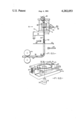
- FIG. 1 is diagramatic side elevational view of part of an apparatus constructed according to the invention.
- FIG. 2 is perspective view, on an enlarged scale, of the cutting mechanism.
- the apparatus 10 comprises a frame 12 on which a cutting head or cutting head assembly 14 is mounted.
- the cutting head is shaped to provide two concentric cutting edges 16, 18 joined by a radially directed cutting edge 20. Additional cutting edges 21, 23 are provided outside the outer edge 16.
- Above the cutting head 14 are positioned a pair of support plates 22, 24 carried on spring mountings 26.
- a presser head 28 having a lowermost plate (unnumbered) is eccentrically driven from a shaft 30 so as to reciprocate above the cutting head assembly 14.
- a guide bar 32 which comprises a length of piping supported by a support plate 34 and carrying a radially directed guide fin 36 down most of its length.
- Spray nozzles 38 and 40 are positioned on either side of the guide bar 32 with a baffle 42 located between.
- Driven rollers 44 having a surface of relatively soft material take the tubular product from guide bar 32 and feed to a take-up drum (not shown).
- Feed rollers 46 positioned immediately adjacent the cutting head 14 are geared to the shaft 30 in such a manner as to urge glass fibre sheet 48 into the cutting zone in timed relationship with the cutting operating.
- a vacuum extract device (not shown) is located adjacent the cutting zone to remove waste.
- glass fibre in the form of a sheet slightly wider than the larger cutting edge 16 is fed stepwise into the cutting zone by the rollers 46 in timed relationship with the operation of the shaft 30 so that a fresh portion of the sheet is presented over the cutting head every time the presser head 28 descends.
- the sheet 48 is supported on the sprung plates 22, 24 and as the presser head descends the plates are pushed below the level of the cutting edges 16, 18, 20, 21, 23 allowing the sheet to be cut.
- the edges 16, 18, 20 produce radially slit rings which are successively pushed down through the cutting head 14, between the edges 16, 18 and on to the guide bar 32, the fin 36 locating and aligning the radial slits of the rings.
- the apparatus of the invention may be used to produce pipe insulation in a continuous manner. Further, two or more cutting heads 14, with associated presser heads 28 and guide bars 32, may be provided side by side with common drive, feed and take-up systems. The waste may be recycled to produce fresh glass fibre sheet, or may be used as an insulating filling for other thermally insulating products.
Landscapes
- Engineering & Computer Science (AREA)
- General Engineering & Computer Science (AREA)
- Mechanical Engineering (AREA)
- Life Sciences & Earth Sciences (AREA)
- Forests & Forestry (AREA)
- Thermal Insulation (AREA)
- Decoration Of Textiles (AREA)
- Insulating Bodies (AREA)
- Lining Or Joining Of Plastics Or The Like (AREA)
- Meat, Egg Or Seafood Products (AREA)
Abstract
Apparatus for forming a tube, preferably of flexible thermally insulating material, comprises a cutting head 14 with a pair of concentric cutting edge 16, 18 which cooperates with a presser head 28 to cut rings 50 of material from a sheet 48 presented to the cutting head. The rings are stacked up on a guide bar 32 and sprayed with a coating composition to consolidate them into a tube which may be collected on a take-up drum in a continuous manner.
Description
This invention relates to an apparatus and method for making tubes, particularly tubes of flexible thermally insulating material suitable for use as pipe insulation.
In our copending U.K. Patent Application No. 2628/77 (German Offenlegungsschrift No. 2800792) there is disclosed insulation for lagging pipes which comprises a plurality of right cylindrical elements of inorganic fibres held together by a surface coating of a flexible material, the elements having a bore therein in which the pipe is to be located and the fibres in the elements lying substantially in planes perpendicular to the cylindrical axis thereof. In the preferred form of the insulation, a plurality of right cylindrical elements are connected together into a tubular length of pipe lagging having a common outer cover.
The invention seeks to provide an apparatus which is capable, inter alia, of making continuous lengths of the above insulation.
According to the present invention there is provided an apparatus which comprises a pair of concentric cutting edges mounted above a guide bar, means for pressing a sheet of material against the cutting edges to cut a ring of material and means for coating the cut rings of material on the guide bar.
The invention also provides a method of making tubes which comprises feeding a sheet of material to a cutting zone, cutting rings of the material, passing the rings along a guide bar, coating the surfaces of the rings on the guide bar, and collecting the tube so-formed.
The sheet of material is preferably an inorganic fibre batt, e.g. glass fibre, and ideally most or all of the fibres in the sheet lie substantially in the plane of the sheet.
The concentric cutting edges preferably have a radially directed interconnected cutting edge so that the rings cut each have a radial slit. In this case the guide bar preferably has a radially directed longitudinal guide fin which will have the effect of aligning the slits in successive rings so that the tube finally produced has a radial slit along its whole length.
The guide bar passes through the bores in the rings formed by the inner concentric cutting edge.
The means for pressing the sheet of material against the cutting edges is preferably a plate, profiled with recesses to the shape of the cutting edges and, ideally, surfaced with a hard-wearing resilient material. The pressing of the plate may be in timed relationship with the feed of sheet material so that a fresh portion of the sheet is presented for each successive cut. In this case the sheet may be fed by means such as a conveyor or feed rollers geared to the pressing means.
As indicated in our copending application referred to above, the coating material is preferably a liquid coating which sets to a flexible coat and which may be applied by dipping, brushing or spraying, especially the latter. Hence the coating means may suitably comprise one or more spray nozzles capable of spraying the coating medium on to the rings passing along the guide bar. The nozzles may be stationary or rotatable about the tube. Depending on the coating material employed, a subsequent heating zone for curing or drying of the coating may be provided. The length of the guide bar should be such that the chosen coating material has cured or set sufficiently to hold the tube intact when it leaves the bar and is collected, e.g. on a take-up drum.
Preferred coating materials include natural or synthetic rubbers or other resinous synthetic materials, for example polyvinylchloride, polyolefines, acrylates, nitrile, thiol, silicone, urethane or chloroprene rubbers, polytetrafluoroethylene or a combination thereof.
The invention will be described further, by way of example, with reference to the accompanying drawings, in which:
FIG. 1 is diagramatic side elevational view of part of an apparatus constructed according to the invention; and
FIG. 2 is perspective view, on an enlarged scale, of the cutting mechanism.
Referring to the drawings, the apparatus 10 comprises a frame 12 on which a cutting head or cutting head assembly 14 is mounted. The cutting head is shaped to provide two concentric cutting edges 16, 18 joined by a radially directed cutting edge 20. Additional cutting edges 21, 23 are provided outside the outer edge 16. Above the cutting head 14 are positioned a pair of support plates 22, 24 carried on spring mountings 26. A presser head 28 having a lowermost plate (unnumbered) is eccentrically driven from a shaft 30 so as to reciprocate above the cutting head assembly 14.
Below the cutting head 14 there is located a guide bar 32 which comprises a length of piping supported by a support plate 34 and carrying a radially directed guide fin 36 down most of its length. Spray nozzles 38 and 40 are positioned on either side of the guide bar 32 with a baffle 42 located between. Driven rollers 44 having a surface of relatively soft material take the tubular product from guide bar 32 and feed to a take-up drum (not shown). Feed rollers 46 positioned immediately adjacent the cutting head 14 are geared to the shaft 30 in such a manner as to urge glass fibre sheet 48 into the cutting zone in timed relationship with the cutting operating. A vacuum extract device (not shown) is located adjacent the cutting zone to remove waste.
In operation, glass fibre in the form of a sheet slightly wider than the larger cutting edge 16 is fed stepwise into the cutting zone by the rollers 46 in timed relationship with the operation of the shaft 30 so that a fresh portion of the sheet is presented over the cutting head every time the presser head 28 descends. The sheet 48 is supported on the sprung plates 22, 24 and as the presser head descends the plates are pushed below the level of the cutting edges 16, 18, 20, 21, 23 allowing the sheet to be cut. The edges 16, 18, 20 produce radially slit rings which are successively pushed down through the cutting head 14, between the edges 16, 18 and on to the guide bar 32, the fin 36 locating and aligning the radial slits of the rings. As the presser head 28 rises, the plates 22, 24 rise under the action of their spring mountings 26 and raise the remainder of the cut sheet to its original level. The edges 21, 23 serve to sever the sheet completely across its width, so as the rollers 46 operate to present a fresh portion of sheet, the cut portion is pushed towards the vacuum extract device which removes the cut portion as waste. Successive cut rings 50 stack up on the guide bar 32 and are sprayed with a coating composition by the nozzles 38, 40. As the coating composition cures, in the zone 52, the rings become consolidated into a tube 54 having a radial slit along its length. The guide bar ends at 56 and the tube 54 is urged forward by the driven rollers 44 on to the take-up drum. The support plate 34 is in the plane of the fin 36 and thus the rings 50 are able to pass by virtue of their radial slits.
The apparatus of the invention may be used to produce pipe insulation in a continuous manner. Further, two or more cutting heads 14, with associated presser heads 28 and guide bars 32, may be provided side by side with common drive, feed and take-up systems. The waste may be recycled to produce fresh glass fibre sheet, or may be used as an insulating filling for other thermally insulating products.
It will be appreciated that although in the above description the presser head is moved while the cutting head is held stationary, in certain circumstances it may be preferable to hold the former stationary and move the latter.
Claims (37)
1. An apparatus which comprises a pair of concentric cutting edges mounted above and aligned with a guide bar along which a ring of material is adapted to be guided, means for pressing a sheet of material against the cutting edges to cut a ring of material and transfer said rings to said guide bar, and means for coating the cut rings of material on the guide bar.
2. An apparatus as claimed in claim 1 in which the cutting edges have a radially directed interconnecting cutting edge adapted to form a radial slit in each of the cut rings.
3. An apparatus as claimed in claim 2 in which the guide bar has a radially directed longitudinal guide fin for registering with each radial slit to guide the cut rings on the guide bar.
4. An apparatus as claimed in any of claims 1 to 3 in which the means for pressing the sheet of material against the cutting edges is a plate.
5. An apparatus as claimed in any claims 1 to 3 including means for feeding a sheet of material between said pressing means and said cutting edges, and the means for pressing the sheet of material against the cutting edges is operable in timed relationship with the sheet material feeding means so that a fresh portion of the sheet is presented for each successive cut.
6. An apparatus as claimed in claim 5 in which the sheet is fed by feed rollers geared to the pressing means.
7. An apparatus as claimed in any of claims 1 to 3 in which the means for coating the cut rings comprise one or more spray nozzles.
8. An apparatus as claimed in claim 7 in which the spray nozzles are arranged to rotate about the cut rings on the guide bar.
9. An apparatus comprising means for cutting successive rings from sheet material, means for guiding the rings for coaxial movement along a predetermined path of travel, and means for coating at least exterior circumferential surfaces of the rings during the movement thereof along the predetermined path.
10. The apparatus as defined in claim 9 including means for forming a radial through slit in each ring.
11. The apparatus as defined in claim 9 including means for forming a radial through slit in each ring, and means for maintaining alignment between all the slits of the rings during at least a portion of the movement of the rings along the predetermined path.
12. The apparatus as defined in claim 9 wherein each ring includes opposite annular faces, said guiding means effects face-to-face guiding movement of the rings along at least a portion of the predetermined path, and said coating means effects a tubular coating surrounding all of the rings and being bonded to the exterior circumferential surfaces thereof.
13. The apparatus as defined in claim 11 wherein each ring includes opposite annular faces, said guiding means effects face-to-face guiding movement of the rings along at least a portion of the predetermined path, and said coating means effects a tubular coating surrounding all of the rings and being bonded to the exterior circumferential surfaces thereof.
14. The apparatus as defined in claim 9 wherein said cutting means is a pair of concentric cutting edges.
15. The apparatus as defined in claim 9 wherein said guiding means is a guide bar.
16. The apparatus as defined in claim 14 wherein said cutting means is defined by means for pressing the sheet material against said cutting edges to cut a ring of material.
17. The apparatus as defined in claim 15 wherein said means for coating coat the cut rings of material on the
18. The apparatus as defined in claim 15 wherein said cutting means is a pair of concentric cutting edges.
19. The apparatus as defined in claim 18 wherein said cutting means is defined by means for pressing the sheet material against said cutting edges to cut a ring of material.
20. The apparatus as defined in claim 19 wherein said means for coating coat the cut rings of material on the guide bar.
21. An apparatus which comprises a pair of concentric cutting edges, pressing means disposed for opposing said pair of concentric cutting edges, means for feeding a sheet of material in a first direction between said pair of concentric edges and said pressing means, means for moving at least one of said pair of concentric cutting edges and said pressing means from a first spaced position to a second relatively more adjacent position during which movement a ring of material is cut from said sheet of material, means for guiding each cut ring of material in a second direction generally normal to said first direction substantially immediately upon the ring of material being cut from the sheet of material, said guiding means being a guide bar in generally internal telescopic relationship to the cut ring and including a portion disposed in generally coaxial relationship to said concentric cutting edges, and means for coating an exterior peripheral surface of the cut ring of material while the latter is on the guide bar.
22. The apparatus as defined in claim 21 wherein said concentric cutting edges are located between said opposing means and said guide bar portion.
23. The apparatus as defined in claim 21 wherein said concentric cutting edges are located between said opposing means and said guide bar portion, and said concentric cutting edges are located vertically above said guide bar portion.
24. The apparatus as defined in claim 21 including means between said concentric cutting edges for cutting a radial slit in each ring generally simultaneously with the cutting of each ring from the sheet of material and generally simultaneously with the relative movement of said concentric cutting edges and said opposing means toward said second relatively more adjacent positions.
25. The apparatus as defined in claim 21 including means for forming a radial through slit in each cut ring, and means for both supporting said guide bar and for maintaining alignment between all the slits of all cut rings during at least a portion of the movement of the cut rings in said second direction along said guide bar.
26. The apparatus as defined in claim 9 including means for feeding sheet material along a first path of travel in a first direction to said cutting means, said cutting means having first and second cooperative portions disposed at generally opposite sides of said first path, means for repetitively moving at least one of said first and second cooperative cutting portions from a first spaced position to a second relatively more adjacent position, during which movement successive rings of material are cut from said sheet of material, guide means in the form of a guide bar having an entrance end portion immediately adjacent to said cutting means and externally telescopically receiving thereon each ring, said guide bar entrance end portion being positioned generally normal to said first direction whereby said guide bar entrance portion guides each ring along a second path generally normal to said first path and in a second direction away therefrom, and the relative movement of said cooperative cutting portions during movement toward said second relatively more adjacent position is in said second direction.
27. The apparatus as defined in claim 26 wherein said second direction is vertical downward.
28. A method of making tubes which comprises feeding a sheet of material to a cutting zone, cutting rings of the material, passing the rings in face-to-face relationship along a guide bar, coating the exterior surfaces of the rings on the guide bar to form a continuous tube, and collecting the tube so-formed.
29. A method as claimed in claim 28 in which the material is an inorganic fibre batt in which most or all of the fibres lie in the plane of the sheet.
30. A method as claimed in claim 29 in which the sheet is of glass fibres.
31. A method as claimed in any of claims 28 to 30 in which the surfaces are coated with a material selected from natural or synthetic rubbers or other synthetic resinous materials.
32. A method as claimed in any of claims 28 to 30 in which the surfaces are coated by spraying.
33. A method comprising the steps of cutting successive rings from sheet material, guiding the rings for coaxial movement along a predetermined path of travel, and coating at least exterior circumferential surfaces of the rings during the movement thereof along the predetermined path.
34. The method as defined in claim 33 including the step of forming a radial through slit in each ring prior to said guiding.
35. The method as defined in claim 33 including the step of forming a radial through slit in each ring, and maintaining alignment between all the slits of the rings during at least a portion of the movement of the rings along the predetermined path.
36. The method as defined in claim 33 wherein each ring includes opposite annular faces, the guiding step effects face-to-face guiding movement of the rings along at least a portion of the predetermined path, and the coating step effects the formation of a tubular coating surrounding all of the rings and being bonded to the exterior circumferential surfaces thereof.
37. The method as defined in claim 35 wherein each ring includes opposite annular faces, the guiding step effects face-to-face guiding movement of the rings along at least a portion of the predetermined path, and the coating step effects the formation of a tubular coating surrounding all of the rings and being bonded to the exterior circumferential surfaces thereof.
Applications Claiming Priority (2)
| Application Number | Priority Date | Filing Date | Title |
|---|---|---|---|
| GB7836729A GB2029925B (en) | 1978-09-13 | 1978-09-13 | Making tubes |
| GB36729/78 | 1978-09-13 |
Publications (1)
| Publication Number | Publication Date |
|---|---|
| US4282053A true US4282053A (en) | 1981-08-04 |
Family
ID=10499653
Family Applications (1)
| Application Number | Title | Priority Date | Filing Date |
|---|---|---|---|
| US06/069,913 Expired - Lifetime US4282053A (en) | 1978-09-13 | 1979-08-27 | Tube forming apparatus and method |
Country Status (10)
| Country | Link |
|---|---|
| US (1) | US4282053A (en) |
| EP (1) | EP0009888B1 (en) |
| JP (1) | JPS5936706B2 (en) |
| CA (1) | CA1138166A (en) |
| DE (1) | DE2966137D1 (en) |
| DK (1) | DK383379A (en) |
| ES (1) | ES484126A1 (en) |
| FI (1) | FI792627A (en) |
| GB (1) | GB2029925B (en) |
| NO (1) | NO792925L (en) |
Families Citing this family (4)
| Publication number | Priority date | Publication date | Assignee | Title |
|---|---|---|---|---|
| US5261991A (en) * | 1986-04-30 | 1993-11-16 | Dana Corporation | Composite tubular elements and methods of fabrication |
| GB2231638B (en) * | 1986-04-30 | 1991-02-20 | Dana Corp | Manufacture of composite vehicle drive shafts |
| JPH066850Y2 (en) * | 1987-03-23 | 1994-02-23 | 株式会社こだま | Accessories for attaching buttons with golf markers |
| CN109014957A (en) * | 2018-08-01 | 2018-12-18 | 广州至简通用设备制造有限公司 | A kind of tuber |
Citations (7)
| Publication number | Priority date | Publication date | Assignee | Title |
|---|---|---|---|---|
| US1029652A (en) * | 1911-06-30 | 1912-06-18 | John Henry White | Insulating material. |
| US2769741A (en) * | 1953-01-19 | 1956-11-06 | Malloran Corp | Method of making a fibrous article |
| US2980572A (en) * | 1956-11-30 | 1961-04-18 | Laminated Shim Company Inc | Method of making a shim |
| US2995172A (en) * | 1958-03-26 | 1961-08-08 | Jack E Glatt | Method and means for joining plastic articles |
| US3149516A (en) * | 1960-04-22 | 1964-09-22 | Reynolds Metals Co | Machine with guide means for product |
| DE2014555A1 (en) * | 1969-03-28 | 1970-11-12 | P,H, Thermal Products Ltd., Baildon, Yorkshire (Großbritannien) | Pipe insulation |
| US4204380A (en) * | 1977-02-15 | 1980-05-27 | L. Schuler Gmbh | Device for conveying, stacking, and packing aligned laminations of electrical machines |
Family Cites Families (3)
| Publication number | Priority date | Publication date | Assignee | Title |
|---|---|---|---|---|
| DE828338C (en) * | 1948-12-25 | 1952-01-17 | Hoechst Ag | Insulation made up of shell segment rings |
| CH536973A (en) * | 1970-11-02 | 1973-05-15 | Inst Rech S Et D Etudes Tech E | Process for waterproof protection and jointing of thermally insulating elements surrounding a pipeline |
| GB1554330A (en) * | 1977-01-21 | 1979-10-17 | Ph Thermal Prod Ltd | Thermal pipe insulation |
-
1978
- 1978-09-13 GB GB7836729A patent/GB2029925B/en not_active Expired
-
1979
- 1979-08-23 FI FI792627A patent/FI792627A/en not_active Application Discontinuation
- 1979-08-27 US US06/069,913 patent/US4282053A/en not_active Expired - Lifetime
- 1979-08-31 CA CA000334922A patent/CA1138166A/en not_active Expired
- 1979-09-03 EP EP79301811A patent/EP0009888B1/en not_active Expired
- 1979-09-03 DE DE7979301811T patent/DE2966137D1/en not_active Expired
- 1979-09-07 JP JP54115082A patent/JPS5936706B2/en not_active Expired
- 1979-09-10 NO NO792925A patent/NO792925L/en unknown
- 1979-09-12 ES ES484126A patent/ES484126A1/en not_active Expired
- 1979-09-13 DK DK383379A patent/DK383379A/en not_active Application Discontinuation
Patent Citations (7)
| Publication number | Priority date | Publication date | Assignee | Title |
|---|---|---|---|---|
| US1029652A (en) * | 1911-06-30 | 1912-06-18 | John Henry White | Insulating material. |
| US2769741A (en) * | 1953-01-19 | 1956-11-06 | Malloran Corp | Method of making a fibrous article |
| US2980572A (en) * | 1956-11-30 | 1961-04-18 | Laminated Shim Company Inc | Method of making a shim |
| US2995172A (en) * | 1958-03-26 | 1961-08-08 | Jack E Glatt | Method and means for joining plastic articles |
| US3149516A (en) * | 1960-04-22 | 1964-09-22 | Reynolds Metals Co | Machine with guide means for product |
| DE2014555A1 (en) * | 1969-03-28 | 1970-11-12 | P,H, Thermal Products Ltd., Baildon, Yorkshire (Großbritannien) | Pipe insulation |
| US4204380A (en) * | 1977-02-15 | 1980-05-27 | L. Schuler Gmbh | Device for conveying, stacking, and packing aligned laminations of electrical machines |
Non-Patent Citations (1)
| Title |
|---|
| Stanley, Frank A., Punches and Dies, New York, McGraw-Hill Book Company, Inc., 1950, pp. 159-160. * |
Also Published As
| Publication number | Publication date |
|---|---|
| GB2029925A (en) | 1980-03-26 |
| DE2966137D1 (en) | 1983-10-13 |
| EP0009888A1 (en) | 1980-04-16 |
| CA1138166A (en) | 1982-12-28 |
| JPS5936706B2 (en) | 1984-09-05 |
| JPS5545892A (en) | 1980-03-31 |
| NO792925L (en) | 1980-03-14 |
| DK383379A (en) | 1980-03-14 |
| ES484126A1 (en) | 1980-04-01 |
| EP0009888B1 (en) | 1983-09-07 |
| FI792627A (en) | 1980-03-14 |
| GB2029925B (en) | 1982-10-06 |
Similar Documents
| Publication | Publication Date | Title |
|---|---|---|
| US3912573A (en) | Apparatus for producing core material for honeycomb panels | |
| SU573122A3 (en) | Device for moulding packaging material web | |
| DE3016568A1 (en) | METHOD AND DEVICE FOR TEXTURING A THERMOPLASTIC FILM | |
| WO2008093117A2 (en) | Apparatus for manufacturing flexible photovoltaic array | |
| DE3545884A1 (en) | DEVICE FOR PRODUCING (CIGARETTE) PACKS FROM AT LEAST ONE FOLDABLE CUT | |
| US4282053A (en) | Tube forming apparatus and method | |
| CH654244A5 (en) | VACUUM MOLDING MACHINE. | |
| DE1597885C3 (en) | Fixing device for heat fusion fixing of toner images | |
| DE2353886B2 (en) | DEVICE FOR THE CONTINUOUS MANUFACTURING OF BAGS FROM A LONGITUDINAL FOLDED, THERMOPLASTIC OR HEAT SEALABLE WEB | |
| DE2601974A1 (en) | DEVICE FOR THE MANUFACTURE OF GLOVES FROM THERMOPLASTIC FILM | |
| US3682747A (en) | Apparatus for forming an impregnated paper web with corrugations or pleats | |
| DE2531082C3 (en) | Device for heat setting a toner image | |
| US2684107A (en) | Method and apparatus for processing fibrous materials | |
| US2416416A (en) | Method of and apparatus for winding tubes | |
| US4140458A (en) | Apparatus for producing a corrugated sheet | |
| EP0598313B1 (en) | Method and apparatus for binding textile surfaces | |
| DE2509814A1 (en) | METHOD AND APPARATUS FOR MANUFACTURING A CYLINDRICAL CORRUGATED MATERIAL ARTICLE | |
| DE2014873C2 (en) | Method and device for producing tube bodies | |
| DE19506777A1 (en) | Process for producing corrugated cardboard and device therefor | |
| DE19619558A1 (en) | Device for connecting a tear strip with a film web | |
| US3783069A (en) | Method and apparatus for producing fibrous tubular articles | |
| DE1571482A1 (en) | Method and device for the production of shaped objects from mineral wool or other fibers | |
| US3819453A (en) | Apparatus for corrugating a web of thin material such as paper, in a continuous process | |
| US4102725A (en) | Method of making a laminar hollow body of angular cross-section and apparatus for performing the method | |
| DE3375756D1 (en) | Coiling and transferring device for wafers |
Legal Events
| Date | Code | Title | Description |
|---|---|---|---|
| STCF | Information on status: patent grant |
Free format text: PATENTED CASE |