US4266399A - Methods of and apparatus for making cable - Google Patents
Methods of and apparatus for making cable Download PDFInfo
- Publication number
- US4266399A US4266399A US06/063,009 US6300979A US4266399A US 4266399 A US4266399 A US 4266399A US 6300979 A US6300979 A US 6300979A US 4266399 A US4266399 A US 4266399A
- Authority
- US
- United States
- Prior art keywords
- unit
- container
- lay
- cable
- plates
- Prior art date
- Legal status (The legal status is an assumption and is not a legal conclusion. Google has not performed a legal analysis and makes no representation as to the accuracy of the status listed.)
- Expired - Lifetime
Links
Images


Classifications
-
- H—ELECTRICITY
- H01—ELECTRIC ELEMENTS
- H01B—CABLES; CONDUCTORS; INSULATORS; SELECTION OF MATERIALS FOR THEIR CONDUCTIVE, INSULATING OR DIELECTRIC PROPERTIES
- H01B13/00—Apparatus or processes specially adapted for manufacturing conductors or cables
- H01B13/02—Stranding-up
- H01B13/04—Mutually positioning pairs or quads to reduce cross-talk
Definitions
- This invention relates to methods of and apparatus for making cable, and, more particularly, to methods and apparatus for making communications cables in which a plurality of reverse oscillated layers of insulated conductors are assembled into a unit that is taken up in a stationary container and used as a supply in a subsequent stranding or cabling operation.
- a plurality of drums may be placed in tandem to provide a required number of conductor pairs for a particular size cable with successive drums usually driven in opposite directions to apply the conductor pairs in layers in which the directions of the helix as between adjacent layers is reversed to impart desirable electrical characteristics to the cable.
- unit type cable structures have generally replaced the drum-stranded layer type.
- the cable includes one or more bound, bundles of twisted pairs of conductors which are referred to as units and which are assembled in apparatus called flyer stranders.
- the stranding is accomplished by paying out the individual twisted pairs of conductors from supply reels mounted in stationary racks through apertured guides or unit faceplates and through stationary unit forming dies onto a reel which is rotated in a cradle to take up the twisted conductor pairs as a flyer bow is revolved about the cradle.
- a plurality of units are assembled into a core in a rotating takeup apparatus which is referred to as a cabling machine.
- Unit type cables have been formed with a so-called false or reverse stranding lay, that is, a lay that reverses direction periodically along the length of the cable.
- Individual units are formed by passing pairs through a faceplate which includes a plurality of openings that may be disposed in concentric circles consistent with a layering arrangement of conductor pairs of the cable design.
- the faceplate of each unit is oscillated through a predetermined angle in a predetermined length of unit.
- they are bound together such as, for example, by a binder tape immediately upon emerging from a unit forming station.
- Cable structures which are manufactured by the two aforementioned approaches differ in several important characteristics.
- the relative position of a conductor pair in one layer of a reverse layer, drum-stranded cable is continuously changing with respect to a conductor pair in an adjacent layer through each stranding lay.
- the relative positions between pairs in adjacent layers in a unit type cable structure remain substantially unchanged. This is of no consequence with respect to crosstalk between conductor pairs in the same layer because that is easily controlled by twist length selection.
- the reverse layer structure is more attractive because pairs exhibiting poor unbalances are not continuously exposed to each other along the length of the cable. Additionally, it has been shown that there is a tendency for conductor pairs to migrate and become displaced from an assigned position in unit type cable structures.
- the unit type approach is beneficial to use with its capability of making larger pair size cables, while incorporating the desirable features of the drum stranding approach. For example, if the electrical characteristics of the unit type cable are satisfactory, the same space per pair with drum stranded cable as a unit type cable may be achieved with a smaller diameter-over-dielectric (DOD) of each insulated conductor. This would permit a reduction in the DOD with an accompanying reduction in the amount of insulation material.
- DOD diameter-over-dielectric
- drum stranded cable may also be brought together, bound and taken up in a rotating takeup which imparts a stranding lay to the unit. In doing so, the stranding overcomes but is perturbated by the individual reverse twists imparted to each pair by the faceplates.
- each of a plurality of strand elements such as, for example, twisted insulated conductor pairs, is advanced through an associated opening of a plurality of spaced openings in a plate, said openings being arranged about a common axis.
- the methods and apparatus of this invention are capable of assembling pairs or quads of insulated conductors as well as single conductors.
- each twisted pair of insulated conductors of a plurality of pairs is advanced through an opening in one of a plurality of concentrically disposed faceplates which are caused to reciprocally rotate in alternately reverse directions.
- the openings in the plates are formed so that the conductor pairs being advanced therethrough are arranged in concentrically disposed layers.
- the layers are gathered together and are bound in each of two directions. Successive increments of length of the unit are then moved downwardly to a position below a stationary container and a lay of one direction is imparted to the unit after which it is guided upwardly through the container, passed over a flyer-capstan at a constant speed and through a flyer distribution tube which directs the unit into the container.
- a lay of a direction opposite to said one direction is imparted to it so that a zero lay or layless cable unit is taken up.
- the flyer-capstan is controlled to cause the cable unit to be taken up in a plurality of convolutions in each successive increment of height of the container to produce a high density package of layless cable.
- This unit of layless cable is then supplied to a stranding or cabling machine in which it is stranded or cabled together with other units.
- a lay is imparted to the cable unit as it is withdrawn from the stationary takeup and subsequently, the single unit or multi-unit cable is jacketed with a plastic material.
- FIG. 1 is an overall perspective view of an apparatus of this invention for making a reverse oscillated layer multi-cable unit for use in making a communications cable;
- FIG. 1A is an enlarged end view of the multi-cable unit which is made by the apparatus of FIG. 1;
- FIG. 2 is an enlarged perspective view of a portion of the apparatus of FIG. 1 and showing a portion of a three layer reverse oscillated layer cable unit which is formed thereby;
- FIG. 3 is a perspective view of a portion of the apparatus shown in FIG. 1 which includes a reverse oscillated layer device for forming a cable unit;
- FIG. 4 is an end view of a plurality of concentrically disposed faceplates which comprise the reverse oscillated layer device of FIG. 2;
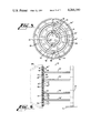
- FIG. 5 is another view of the face plates shown in FIG. 4 along with mechanisms for oscillating the plates;
- FIG. 6 is a side elevational view of the plates of FIG. 5 and a mounting arrangement for same;
- FIG. 7 is a perspective view of a portion of the apparatus of FIG. 1 for taking up a plurality of convolutions of the cable unit;
- FIG. 8 is an enlarged perspective view of a portion of the apparatus shown in FIG. 7;
- FIG. 8A is an enlarged view of a portion of the apparatus which is shown in FIG. 8;
- FIG. 9 is a preferred embodiment of a drive system which is used to control and move the takeup system shown in FIG. 7;
- FIG. 10 is an alternate embodiment of a drive system for controlling and moving the takeup system
- FIG. 11 is a perspective view of an apparatus into which are fed a plurality of units or multi-units made by apparatus of this invention and which forms the units or multi-units into a cable core;
- FIGS. 12 and 13 are cross sectional views of the cable core which is made with the apparatus of FIG. 11 and taken at spaced points along the core.
- FIGS. 1 and 2 there is shown an apparatus, designated generally by the numeral 29, for making reverse oscillated layer cable units 30--30 in accordance with this invention.
- Each unit 30 in a preferred embodiment is comprised of a center or core portion 31 and two concentric layers 32 and 33.
- the center portion 31 includes a plurality of twisted pairs 35--35 of insulated conductors 34--34 with each pair having a conventional twist, i.e. one direction twist along its entire length, or a so-called right hand-left hand (S-Z) twist, which may be made in accordance with methods and apparatus disclosed and claimed in copending, commonly assigned applications Ser. No. 957,772 in the names of J. M. Carter et al filed Nov. 6, 1978 and now U.S. Pat.
- a layer 32 which is applied over the center portion or layer 31 is comprised of a plurality of strands or conductor pairs 40--40 which are greater in number than the number of pairs 35--35 in the layer 31.
- the inner layer 31 is typically comprised of three conductor pairs 35--35 while the layer 32 will have nine.
- the layer 33 is typically comprised of thirteen conductor pairs 45--45 so that the three layers form a twenty-five conductor pair unit.
- Crosstalk is always likely to occur between two conductors in a communication cable that lie parallel and in proximity to each other. The likelihood of crosstalk between conductors in different layers and the center portion 31 is removed if they are twisted with opposite directions of lay.
- the layer 32 is twisted with a lay in one direction followed by a reversal point and a length having a lay in the opposite direction.
- the layer 33 is constructed to have a right hand lay for a predetermined length followed by a left hand lay in the other direction for a predetermined length. Between the predetermined lengths, the strands or conductor pairs 45--45 of the layer 33 pass through a reversal point 48 whereat the direction of lay reverses.
- This pattern of twists, counter or reverse twists and reversal points is repeated periodically along the length of the cable in each of the layers and in the center portion 31.
- the corresponding lays in adjacent layers are reversed in direction, an exact correspondence of reversal as between conductors in adjacent layers is not absolutely necessary to reduce crosstalk.
- a first binder tape is wrapped about the unit 30 in one direction and a second binder tape is wrapped thereover in an opposite direction.
- the alternate bindings prevent the conductor pairs in the layers from coming out of their respective lay directions.
- the unit 30 is either jacketed or it is assembled together with a plurality of other similarly produced units to form a multi-unit cable.
- the apparatus 29 is capable of manufacturing a plurality of reverse oscillated layer cable units 30--30 which are assembled into a multi-unit core 50 shown in FIG. 1A.
- the apparatus 29 includes a plurality of pay off stands 51--51 each of which includes a plurality of individual reels 52--52 of twisted pairs of insulated conductors 35--35 or 40--40 or 45--45. As will be recalled, these may be either unidirectionally twisted pairs or those having a so-called S-Z twist.
- Predetermined groups of the conductor pairs 35--35 are moved through an associated one of a plurality of devices designated reverse oscillated lay (hereinafter referred to as "ROL") devices and further designated generally by the numeral 55.
- ROL reverse oscillated lay
- Each of the devices 55--55 produces a multi-layer unit 30 which is then advanced through a binder 56 that applies a first and second binder to each unit.
- the bound units 30--30 are then advanced through an overlay binder 57 that binds them together into the multi-unit core 50.
- FIG. 1 shows a plurality of pay-off stands and a plurality of ROL devices 55--55
- the invention in a more basic embodiment would include one ROL device for producing a three layer unit having three, nine and thirteen conductors, respectively, in the three layers.
- the multi-unit or single unit cable is advanced past sheaves 58 and 59 thence past sheave 61 up through a center passage of a takeup in the form of a stationary container 62.
- a right hand twist is imparted thereto.
- the cable unit 30 is then moved through a flyer capstan, designated generally by the numeral 65, which causes it to be deposited within the container 62 in a plurality of increments 66--66 of height in convolutions of varying size while a substantially constant line speed is maintained.
- a flyer capstan designated generally by the numeral 65
- a left hand twist is imparted thereto which neutralizes the priorly imparted right hand twist and results in a "dead" cable being arranged within the barrel.
- the substantially constant line speed is advantageous in that expensive synchronization of take-up and supply stand motors is avoided. Moreover, speed changes which are obviated by this invention could cause a pull out of the reverse lay within the layers.
- the container 62 is moved to another location and the unit 30 or multiunit 50 is payed out to be cabled with other units or multiunits. As this is done, a unidirectional lay is imparted to the unit and each conductor pair thereof.
- FIG. 3 shows a portable means 70 for supporting one of the reverse oscillating layer devices 55--55 as well as a binder and footage counter. Because it is portable, the means 70 as well as other cable-making apparatus may be integrated into a line to produce a particular type cable.
- a line shaft 71 extends along in a housing 72 and includes a drive train 73 for turning a shaft 74 that has a sprocket 76 at one end thereof.
- a chain 77 passes around the sprocket 76 and is mounted to a sprocket 78 which is attached to a drive shaft 75, that is connected through a conically shaped member 80 to the ROL device 55. Reverse oscillation of the member 80 and of the ROL device 55 in FIG.
- Another end of the line shaft 71 has a pulley and belt arrangement 82 for imparting rotary motion to a shaft 83 which turns a pulley 84 to move a belt 86 and pulley 87 to turn the head 56 to bind the unit 30.
- FIG. 4 shows an ROL device 55 for forming the three layer unit 30.
- Each of three concentrically disposed plates 88, 89 and 90 includes a plurality of guides in the form of openings 88'--88', 89'--89' and 90'--90', respectively.
- a conductor pair 35 is passed through each of the openings 88'--88', a pair 40 through each of the openings 89'--89' and a pair 45 through each of the openings 90'--90'.
- Each of the openings 88'--88', 89'--89' and 90'--90' typically is about 1.0 cm in diameter; of course, when the ROL device 55 is used to lay up twenty-five pair units, for example, instead of twisted pairs, the size of each opening is on the order of 3.2 cm.
- FIGS. 5 and 6 there is shown an arrangement for causing reverse oscillation, i.e. reciprocating rotation in alternately reverse directions of the plates 88, 89, and 90 of the ROL device 55.
- a plate 88" which is associated with and attached to the plate 88 is constructed with a plurality of teeth 91 about an outer periphery and a plurality of openings 92--92 which are aligned with the openings 88'--88' in the plate 88.
- the plate 89 has an associated ring plate 89" which has a plurality of teeth 93--93 formed about an outer and an inner periphery thereof and a plurality of openings 94--94 which are aligned with the openings 89'--89' in the plate 89.
- a plate 90" is associated with and attached to the plate 90' and has a plurality of peripherally disposed teeth 95 and a plurality of openings 96--96 which are aligned with the openings 90'--90'.
- the member 80 which is attached to the drive shaft 75 is also attached to outer portions of the ring plate 90 and causes, for example, an initial clockwise motion of the ring plate 90 which rotates a pinion 98 clockwise to drive the inner ring plate 89 counterclockwise. This turns a pinion 99 counterclockwise to turn the inner plate 88 clockwise.
- the overall effect is three concentrically disposed plates with adjacent plates being oscillated in opposite directions.
- a pinion (not shown) could be meshed with the ring plate 90 and connected to the shaft 75 which is turned to oscillate the ring plates in alternating opposite directions.
- each of the pinions 98 and 99 is attached to an associated rod 98' and 99', respectively, which are mounted in and extend from the stationary plate 81. In this way, the entire assembly of faceplates and driving mechanisms is supported from the plate 81 and hence from the housing 72.
- the takeup 60 which includes the closed or open sided container 62 that is stationary during takeup and which may include vertical posts 102--102 with wire mesh 103 thereabout or may include a solid side wall (not shown). It is to be understood that the takeup 60 is also used for a multiunit 50 with the same operation as that to be described for the single unit 30.
- the takeup 60 includes a system 100 which controls the deposition of the convolutions or loops of the unit 30 or multi-unit 50 in the container 62 while maintaining line speed of the unit.
- the system 100 includes a motor 104 that turns at line speed and that is connected through a belt 106 to a reducer 107.
- the reducer 107 is connected through a belt 108 to a right angle gear box 109 which provides a direct input to a differential unit 110, and to a positive infinitely variable transmission 111 (hereinafter referred to as "PIV" transmission) through a belt 115.
- the differential unit may be one such as that marketed commercially by Fairchild Industrial Products Division under the trade name "Specon” while the PIV transmission may be one such as horizontal model TD-44 also marketed by Fairchild.
- An output shaft of the PIV transmission 111 is connected by belting 113 and a shaft 114 to right angle gear box 112 which turns a vertically disposed flyer head input drive shaft 105.
- the reducer 107 also drives a belt 116, turns a gear unit 117 to turn two coupled pulleys 118 and 119, and rotates shaft 121 which inputs the PIV transmission 111 through a cam 122 and linkage 123.
- the cam 122 is programmed through a predetermined contour so that it is effective to control the diameter of the loops or convolutions of the unit 30 which are deposited in the container 62.
- the differential unit 110 also has a shaft 126 extending therefrom to a right angle gear box 127 which turns a vertically disposed capstan input drive shaft 128 and attached sprocket 129.
- the unit 30 or multi-unit 50 which is deposited in each layer is caused to generally follow an Archimedes spiral. Because of this pattern pattern of distribution, the speed of revolution of the flyer capstan 65 cannot be changed linearly; rather, the cam 122 is constructed with a contour which changes the speed as the deposition proceeds inwardly and outwardly in each layer within the container 62. An infinite range of speed changes as predetermined by the contour of the cam 122 can be accommodated by the PIV transmission 111.
- the differential unit 110 is designed so that the line speed of the unit 30 and the speed of revolution of the flyer capstan 65 are inputs thereto.
- the output of the differential unit 110 is that speed in RPM which is necessary to pull the cable unit 30 through the apparatus 29 at a constant speed while the flyer input shaft 105 changes its rotational speed to obtain the sequentially increasing and decreasing size loops in each layer 66.
- the flyer-capstan 75 for causing successive increments of the cable unit 30 or the multi-unit 50 to be deposited in a predetermined pattern in the container 62.
- the flyer-capstan 65 includes a capstan sheave 130 which is rotated about its axis by a drive train which extends from the shaft 128 to advance successive increments of the unit 30 or multi-unit 50.
- the capstan sheave 130 is also caused to revolve about the vertical axis of the container 62 by a drive train which extends from the shaft 105 to cause the unit 30 or the multi-unit 50 to be deposited in layers in a predetermined pattern.
- the capstan wheel 130 is supported rotatably on a pin which extends between a pair of downwardly depending arms 131--131 which straddle the wheel and which are attached to flyer-capstan shaft 132 that has a sprocket 133 attached to an upper end thereof.
- Sprockets 134 and 136 are connected together and mounted on a bearing assembly 137, which is rotatable independently, but coaxially with, the flyer shaft 132.
- the capstan input drive shaft 128 which controls the advance of the unit 30 has an upper portion supported in a bearing 138 and has the sprocket 129 attached to the upper end thereof.
- a drive chain 141 passes around the sprocket 129, around a tensioning sprocket 140 and then around the sprocket 134.
- the driving of the capstan 65 is accomplished through a chain 147 that passes around a sprocket 148 to drive a shaft 149 to turn bevel gears 151 and 152.
- These bevel gears turn a gear 153 to turn a pulley 154 over which passes a belt 156.
- the belt 156 passes around pulleys 157 and 158 and is caused by these pulleys to engage a predetermined portion of the periphery of the capstan wheel 130.
- the drive train for revolving the capstan sheave 130 includes a chain 159 that passes around a tensioning sprocket 161 and a sprocket 162 that is attached to an upper end of the previously mentioned flyer head input drive shaft 105.
- the programmed cam 122 controls the turning of the shaft 105 to control the shaft 132 and hence the revolution of the capstan wheel 130 to achieve a predetermined pattern of loops in each layer in the container 62.
- the above-described arrangement provides a differential drive for the capstan 65 and a constant speed for the cable unit 30 or the multi-unit 50. This facilitates the change in the size of the loops being deposited which permits a layering and results in a dense package without changing the speed of the cable unit through the apparatus.
- FIG. 9 there is shown a schematic view of the system 100, for controlling the deposition of convolutions of the cable unit 30 or the multi-unit 50 in the container and for maintaining the line speed of the unit substantially constant.
- This view schematically shows the system which is used to drive the capstan 65 and to revolve the capstan 130 about the vertical axis through the container 62.
- the motor 104 inputs the differential unit 110 as well as the PIV transmission 111.
- the PIV transmission 111 which is modulated by the programmable cam 122, inputs and controls the operation of the flyer drive shaft 105 to turn the shaft 132 and revolve the flyer-capstan 65 about the vertical axis of the container 62. This is accomplished independently of the capstan drive shaft 128 which is controlled by an output of the differential unit 110.
- an output of the PIV unit 111 is fed into the differential unit 110 together with an input of the motor 104 which controls the capstan drive shaft 128 to maintain a constant line speed notwithstanding changes in the speed of revolution to deposit varying size loops in accordance with the predetermined pattern.
- the motor 104 turns a sprocket 171, and turns a chain 172 mounted about a second sprocket 173 which is attached to a shaft 174 extending from a first PIV unit 175.
- the motor 104 also inputs a second PIV unit 176 which outputs to the capstan drive shaft 128 while the first PIV unit outputs to the flyer drive 105.
- the PIV units 175 and 176 are modulated by programmable cams 177 and 178 mounted on a common shaft 179.
- Testing reverse oscillated layer cable units 30--30 or multi-units 50--50 may be conducted as they are made by this invention.
- the testing is accomplished by connecting a test set 180 (see FIG. 1) to an initially deposited end of the unit 30 in the takeup container 62 with high voltage electrodes 181--181, which spark over, being positioned between the supply stands 51--51 and the ROL devices 55--55.
- the unit 30 or multi-unit 50 which is comprised of a plurality of units 30--30 is subsequently withdrawn from the container 62, a unidirectional stranding lay imparted thereto, and then it is formed into a completed cable with such additional steps, as for example, jacketing.
- a plurality of units 30--30 or a plurality of multi-units 50--50 in containers are supplied to an apparatus designated generally by the numeral 182 (see FIG. 11) for assembling the units into a core which is subsequently jacketed.
- the apparatus 182 includes an oscillation station 183 and a binding station 185 which are mounted on a frame 184.
- the oscillation station 183 includes a stationary entrance plate 186 and a plurality of spaced faceplates 187, 188, 189 and 190, each of which includes a plurality of openings and each of which is mounted for oscillating motion.
- the number of angularly oscillatory mounted faceplates which are required between the fixed plate 183 and the final oscillating plate is a function of the angle of oscillation of the latter since the maximum angle of oscillation of each oscillating plate relative to the preceding plate must be less than ⁇ 90° if rubbing of the strand elements being passed therethrough at a point between the plates is to be avoided.
- the plate 187 is mounted to oscillate 90° in one direction, then 90° in another direction; the plate 188, 180° in each direction; the plate 189, 270° in each direction, and finally the plate 190, 360° in each direction.
- This may be accomplished in an expanded arrangement of that shown in FIG. 3 in which the shaft 74 drives all of the faceplates but through gearing having successively changed teeth arrangements in order to achieve the required angular oscillations.
- the units 30--30 or multi-units 50--50 emerge from the openings in the last plate 190, they are passed through gathering dies 191--191 which size the assembly into a core. Then the core is passed through binder heads 192 and 193 in the binding station 185 which bind the core in opposite directions in preparation for subsequent shielding and jacketing operations.
- the units 30--30 or the multi-units 50--50 are advanced through the apparatus 182, they are caused to have a periodically reversed lay. However, this is accomplished in a way, which is referred to as the floating carriage technique in drum stranding, such that the unidirectional lay of the conductors pairs is maintained. Comparing FIGS. 12 and 13, it can be seen that, although the units in the final cable core have a periodically reversed lay, the circular orientation of each unit or multiunit with respect to its longitudinal axis is not changed.
Landscapes
- Engineering & Computer Science (AREA)
- Manufacturing & Machinery (AREA)
- Communication Cables (AREA)
- Ropes Or Cables (AREA)
- Processes Specially Adapted For Manufacturing Cables (AREA)
Priority Applications (8)
| Application Number | Priority Date | Filing Date | Title |
|---|---|---|---|
| US06/063,009 US4266399A (en) | 1979-08-02 | 1979-08-02 | Methods of and apparatus for making cable |
| PCT/US1980/000905 WO1981000483A1 (en) | 1979-08-02 | 1980-07-21 | Methods of and apparatus for making cable and product produced thereby |
| JP50191980A JPS56500987A (de) | 1979-08-02 | 1980-07-21 | |
| DE8080901608T DE3070549D1 (en) | 1979-08-02 | 1980-07-21 | Method of making cable |
| CA000356850A CA1135576A (en) | 1979-08-02 | 1980-07-23 | Methods of and apparatus for making cable and product produced thereby |
| EP80901608A EP0032945B1 (de) | 1979-08-02 | 1981-02-24 | Verfahren zur herstellung von kabeln |
| US06/239,716 US4372105A (en) | 1979-08-02 | 1981-03-02 | Reverse oscillated lay cable |
| US06/239,820 US4342434A (en) | 1979-08-02 | 1981-03-02 | Apparatus for depositing cable |
Applications Claiming Priority (1)
| Application Number | Priority Date | Filing Date | Title |
|---|---|---|---|
| US06/063,009 US4266399A (en) | 1979-08-02 | 1979-08-02 | Methods of and apparatus for making cable |
Related Child Applications (2)
| Application Number | Title | Priority Date | Filing Date |
|---|---|---|---|
| US06/239,716 Division US4372105A (en) | 1979-08-02 | 1981-03-02 | Reverse oscillated lay cable |
| US06/239,820 Division US4342434A (en) | 1979-08-02 | 1981-03-02 | Apparatus for depositing cable |
Publications (1)
| Publication Number | Publication Date |
|---|---|
| US4266399A true US4266399A (en) | 1981-05-12 |
Family
ID=22046299
Family Applications (2)
| Application Number | Title | Priority Date | Filing Date |
|---|---|---|---|
| US06/063,009 Expired - Lifetime US4266399A (en) | 1979-08-02 | 1979-08-02 | Methods of and apparatus for making cable |
| US06/239,716 Expired - Lifetime US4372105A (en) | 1979-08-02 | 1981-03-02 | Reverse oscillated lay cable |
Family Applications After (1)
| Application Number | Title | Priority Date | Filing Date |
|---|---|---|---|
| US06/239,716 Expired - Lifetime US4372105A (en) | 1979-08-02 | 1981-03-02 | Reverse oscillated lay cable |
Country Status (6)
| Country | Link |
|---|---|
| US (2) | US4266399A (de) |
| EP (1) | EP0032945B1 (de) |
| JP (1) | JPS56500987A (de) |
| CA (1) | CA1135576A (de) |
| DE (1) | DE3070549D1 (de) |
| WO (1) | WO1981000483A1 (de) |
Cited By (13)
| Publication number | Priority date | Publication date | Assignee | Title |
|---|---|---|---|---|
| US4359860A (en) * | 1980-06-21 | 1982-11-23 | Kabel-Und Metallwerke Gutehoffnungshutte Ag | Making electrical cable |
| EP0079199A1 (de) * | 1981-11-05 | 1983-05-18 | Western Electric Company, Incorporated | Nachrichtenkabel und Verfahren zu dessen Herstellung |
| US4459799A (en) * | 1982-04-09 | 1984-07-17 | Les Cables De Lyon | Quad guide device for guiding quads to a telephone cable stranding machine |
| US4995163A (en) * | 1987-04-22 | 1991-02-26 | The Perkin-Elmer Corporation | Method of assembling a chromatography column |
| US5546741A (en) * | 1992-04-03 | 1996-08-20 | Nokia-Maillefer Oy | Reverse stranding apparatus and methods |
| WO2001073192A1 (es) * | 2000-03-31 | 2001-10-04 | Construcciones Mecanicas Caballe, Sa | Maquina cableadora de torsión alterna tipo sz multiconductora |
| US6411403B1 (en) | 2000-01-04 | 2002-06-25 | Fitel Usa Corp. | Polyamide/polyolefinfiber optic buffer tube material |
| US6421486B1 (en) | 1999-07-01 | 2002-07-16 | Fitel Usa Corp. | Extruded buffer tubes comprising polyolefin resin based color concentrates for use in fiber optic cables |
| US6433272B1 (en) | 2000-09-19 | 2002-08-13 | Storage Technology Corporation | Crosstalk reduction in constrained wiring assemblies |
| CN101728031B (zh) * | 2010-02-01 | 2011-11-09 | 领亚电子科技股份有限公司 | 多层多股绞线方法及实施该方法的装置 |
| US20150371733A1 (en) * | 2013-03-07 | 2015-12-24 | Huber+Suhner Ag | Sealed conductor cable |
| CN109594376A (zh) * | 2019-01-23 | 2019-04-09 | 上海奋为船舶技术有限公司 | 海工缆绳制股用引线盘组 |
| US20250116063A1 (en) * | 2023-10-05 | 2025-04-10 | Rio M&C Co., Ltd. | Continuous stranding system |
Families Citing this family (9)
| Publication number | Priority date | Publication date | Assignee | Title |
|---|---|---|---|---|
| DE3403864A1 (de) * | 1984-02-02 | 1985-08-08 | Siemens AG, 1000 Berlin und 8000 München | Vorrichtung zum lagenverseilen |
| US4947637A (en) * | 1989-03-14 | 1990-08-14 | The United States Of America As Represented By The United States Department Of Energy | Method and apparatus for making multistrand superconducting cable |
| US6140589A (en) * | 1997-04-04 | 2000-10-31 | Nextrom, Ltd. | Multi-wire SZ and helical stranded conductor and method of forming same |
| US6215062B1 (en) * | 1999-03-23 | 2001-04-10 | Ray Latham Kimber | Multi-conductor braided cable |
| US7115815B2 (en) * | 2003-10-31 | 2006-10-03 | Adc Telecommunications, Inc. | Cable utilizing varying lay length mechanisms to minimize alien crosstalk |
| US7214884B2 (en) * | 2003-10-31 | 2007-05-08 | Adc Incorporated | Cable with offset filler |
| US7173189B1 (en) | 2005-11-04 | 2007-02-06 | Adc Telecommunications, Inc. | Concentric multi-pair cable with filler |
| US7375284B2 (en) * | 2006-06-21 | 2008-05-20 | Adc Telecommunications, Inc. | Multi-pair cable with varying lay length |
| US20180096750A1 (en) * | 2016-10-05 | 2018-04-05 | Yazaki Corporation | Composite twisted wire conductor and insulated wire provided with same |
Citations (9)
| Publication number | Priority date | Publication date | Assignee | Title |
|---|---|---|---|---|
| US3023977A (en) * | 1958-12-08 | 1962-03-06 | Donald P Whitacre | Wire coiling machine |
| US3187495A (en) * | 1961-10-12 | 1965-06-08 | Anaconda Wire & Cable Co | Method and apparatus for stranding cable |
| US3572024A (en) * | 1967-11-01 | 1971-03-23 | British Insulated Callenders | Manufacture of electric cables |
| US3757505A (en) * | 1970-02-25 | 1973-09-11 | Ericsson Telefon Ab L M | Apparatus for changing the relative position of the conductors during the manufacture of a telecommunication cable |
| US3843072A (en) * | 1973-02-12 | 1974-10-22 | Western Electric Co | Method of and apparatus for coiling wire |
| US3884025A (en) * | 1972-08-11 | 1975-05-20 | Siemens Ag | Method and apparatus for making SZ-twisted communications cable |
| US3979897A (en) * | 1974-01-25 | 1976-09-14 | Siemens Aktiengesellschaft | Method for locating conductor breaks during the two stage twisting of a communications cable |
| US4056925A (en) * | 1974-11-15 | 1977-11-08 | Siemens Aktiengesellschaft | Method and apparatus for the SZ-twisting of electrical cables |
| US4127982A (en) * | 1976-10-23 | 1978-12-05 | Felten & Guilleaume Kabelwerke Gmbh | Method of and an apparatus for manufacturing a SZ twisted strand of elongated elements for telecommunication cables |
Family Cites Families (6)
| Publication number | Priority date | Publication date | Assignee | Title |
|---|---|---|---|---|
| DE631929C (de) | 1931-11-20 | 1936-06-29 | Hackethal Draht Und Kabel Werk | Verfahren und Vorrichtung zur Herstellung von lagenweise aufgebauten Fernmeldekabeln |
| US3025656A (en) * | 1957-07-17 | 1962-03-20 | Cook Foundation Inc | Method and apparatus for making communication cable |
| FR1231658A (fr) * | 1958-03-03 | 1960-09-30 | Siemens Ag | Procédé d'obtention d'éléments de câblage à conducteurs individuels, en particulier à quatre conducteurs en étoile, pour la fabrication de câbles de télécommunication |
| US3324233A (en) * | 1965-04-08 | 1967-06-06 | Amphenol Corp | Cable complex employing strand twist reversal to absorb longitudinal expansion |
| DE2828959C2 (de) * | 1978-06-28 | 1980-05-29 | Siemens Ag, 1000 Berlin Und 8000 Muenchen | Verfahren zum lagenweisen SZ-Verseilen von Verseilelementen elektrischer oder optischer Kabel |
| US4182107A (en) * | 1978-11-06 | 1980-01-08 | Western Electric Company, Inc. | Method of forming S-Z twisted strand units |
-
1979
- 1979-08-02 US US06/063,009 patent/US4266399A/en not_active Expired - Lifetime
-
1980
- 1980-07-21 WO PCT/US1980/000905 patent/WO1981000483A1/en not_active Ceased
- 1980-07-21 DE DE8080901608T patent/DE3070549D1/de not_active Expired
- 1980-07-21 JP JP50191980A patent/JPS56500987A/ja active Pending
- 1980-07-23 CA CA000356850A patent/CA1135576A/en not_active Expired
-
1981
- 1981-02-24 EP EP80901608A patent/EP0032945B1/de not_active Expired
- 1981-03-02 US US06/239,716 patent/US4372105A/en not_active Expired - Lifetime
Patent Citations (9)
| Publication number | Priority date | Publication date | Assignee | Title |
|---|---|---|---|---|
| US3023977A (en) * | 1958-12-08 | 1962-03-06 | Donald P Whitacre | Wire coiling machine |
| US3187495A (en) * | 1961-10-12 | 1965-06-08 | Anaconda Wire & Cable Co | Method and apparatus for stranding cable |
| US3572024A (en) * | 1967-11-01 | 1971-03-23 | British Insulated Callenders | Manufacture of electric cables |
| US3757505A (en) * | 1970-02-25 | 1973-09-11 | Ericsson Telefon Ab L M | Apparatus for changing the relative position of the conductors during the manufacture of a telecommunication cable |
| US3884025A (en) * | 1972-08-11 | 1975-05-20 | Siemens Ag | Method and apparatus for making SZ-twisted communications cable |
| US3843072A (en) * | 1973-02-12 | 1974-10-22 | Western Electric Co | Method of and apparatus for coiling wire |
| US3979897A (en) * | 1974-01-25 | 1976-09-14 | Siemens Aktiengesellschaft | Method for locating conductor breaks during the two stage twisting of a communications cable |
| US4056925A (en) * | 1974-11-15 | 1977-11-08 | Siemens Aktiengesellschaft | Method and apparatus for the SZ-twisting of electrical cables |
| US4127982A (en) * | 1976-10-23 | 1978-12-05 | Felten & Guilleaume Kabelwerke Gmbh | Method of and an apparatus for manufacturing a SZ twisted strand of elongated elements for telecommunication cables |
Cited By (15)
| Publication number | Priority date | Publication date | Assignee | Title |
|---|---|---|---|---|
| US4359860A (en) * | 1980-06-21 | 1982-11-23 | Kabel-Und Metallwerke Gutehoffnungshutte Ag | Making electrical cable |
| EP0079199A1 (de) * | 1981-11-05 | 1983-05-18 | Western Electric Company, Incorporated | Nachrichtenkabel und Verfahren zu dessen Herstellung |
| EP0092583A4 (de) * | 1981-11-05 | 1984-10-16 | Western Electric Co | Fernmeldekabel und dessen herstellungsverfahren. |
| US4459799A (en) * | 1982-04-09 | 1984-07-17 | Les Cables De Lyon | Quad guide device for guiding quads to a telephone cable stranding machine |
| US4995163A (en) * | 1987-04-22 | 1991-02-26 | The Perkin-Elmer Corporation | Method of assembling a chromatography column |
| US5546741A (en) * | 1992-04-03 | 1996-08-20 | Nokia-Maillefer Oy | Reverse stranding apparatus and methods |
| US6421486B1 (en) | 1999-07-01 | 2002-07-16 | Fitel Usa Corp. | Extruded buffer tubes comprising polyolefin resin based color concentrates for use in fiber optic cables |
| US6411403B1 (en) | 2000-01-04 | 2002-06-25 | Fitel Usa Corp. | Polyamide/polyolefinfiber optic buffer tube material |
| WO2001073192A1 (es) * | 2000-03-31 | 2001-10-04 | Construcciones Mecanicas Caballe, Sa | Maquina cableadora de torsión alterna tipo sz multiconductora |
| US6433272B1 (en) | 2000-09-19 | 2002-08-13 | Storage Technology Corporation | Crosstalk reduction in constrained wiring assemblies |
| CN101728031B (zh) * | 2010-02-01 | 2011-11-09 | 领亚电子科技股份有限公司 | 多层多股绞线方法及实施该方法的装置 |
| US20150371733A1 (en) * | 2013-03-07 | 2015-12-24 | Huber+Suhner Ag | Sealed conductor cable |
| US9761352B2 (en) * | 2013-03-07 | 2017-09-12 | Huber+Suhner Ag | Sealed conductor cable |
| CN109594376A (zh) * | 2019-01-23 | 2019-04-09 | 上海奋为船舶技术有限公司 | 海工缆绳制股用引线盘组 |
| US20250116063A1 (en) * | 2023-10-05 | 2025-04-10 | Rio M&C Co., Ltd. | Continuous stranding system |
Also Published As
| Publication number | Publication date |
|---|---|
| EP0032945A4 (de) | 1982-11-08 |
| EP0032945A1 (de) | 1981-08-05 |
| WO1981000483A1 (en) | 1981-02-19 |
| DE3070549D1 (en) | 1985-05-30 |
| JPS56500987A (de) | 1981-07-16 |
| EP0032945B1 (de) | 1985-04-24 |
| US4372105A (en) | 1983-02-08 |
| CA1135576A (en) | 1982-11-16 |
Similar Documents
| Publication | Publication Date | Title |
|---|---|---|
| US4266399A (en) | Methods of and apparatus for making cable | |
| US3187495A (en) | Method and apparatus for stranding cable | |
| US3507108A (en) | Method of producing s-z alternating twists and the apparatus therefor | |
| US3025656A (en) | Method and apparatus for making communication cable | |
| US3715877A (en) | Communication cable | |
| US2412196A (en) | Method of and apparatus for producing stranded cables | |
| US3732682A (en) | Methods of and apparatus for twisting and stranding cable pairs in a tandem operation | |
| US1956730A (en) | Method of making electrical cables | |
| US3373550A (en) | Methods of and apparatus for alternate-reverse twisting of indefinite lengths of strand material | |
| US3091074A (en) | Apparatus for producing communication cables | |
| US4266398A (en) | Method and apparatus for the layerwise SZ twisting of elements of electrical or optical cables | |
| US4342434A (en) | Apparatus for depositing cable | |
| US2941348A (en) | Manufacture of wire strands, bunches, and cables | |
| US2572052A (en) | Method and machine for making electric communication cables | |
| US3369355A (en) | Stranding apparatus and method and cable made thereby | |
| US1988586A (en) | Quad stranding machine | |
| US3114232A (en) | Method and apparatus for producing improved conductor cables | |
| US3061997A (en) | Method and apparatus for producing improved conductor cables | |
| US4182107A (en) | Method of forming S-Z twisted strand units | |
| US4397141A (en) | Method and apparatus for making balanced metallic strand | |
| CA2176774C (en) | Method for twisting strand material | |
| US4577403A (en) | Manufacture of telecommunications cable core units | |
| US3335634A (en) | Method and apparatus for braiding rope | |
| US3138915A (en) | Method of forming a sectorconductor cable | |
| US1813197A (en) | Cable forming apparatus |
Legal Events
| Date | Code | Title | Description |
|---|---|---|---|
| STCF | Information on status: patent grant |
Free format text: PATENTED CASE |
|
| AS | Assignment |
Owner name: AT & T TECHNOLOGIES, INC., Free format text: CHANGE OF NAME;ASSIGNOR:WESTERN ELECTRIC COMPANY, INCORPORATED;REEL/FRAME:004251/0868 Effective date: 19831229 |