US4265717A - Method and apparatus for protecting electrodes from thermal shock during start up - Google Patents
Method and apparatus for protecting electrodes from thermal shock during start up Download PDFInfo
- Publication number
- US4265717A US4265717A US06/092,441 US9244179A US4265717A US 4265717 A US4265717 A US 4265717A US 9244179 A US9244179 A US 9244179A US 4265717 A US4265717 A US 4265717A
- Authority
- US
- United States
- Prior art keywords
- cell
- cathode
- metal
- melting point
- aluminum
- Prior art date
- Legal status (The legal status is an assumption and is not a legal conclusion. Google has not performed a legal analysis and makes no representation as to the accuracy of the status listed.)
- Expired - Lifetime
Links
- 238000000034 method Methods 0.000 title claims abstract description 27
- 230000035939 shock Effects 0.000 title abstract description 19
- 229910052751 metal Inorganic materials 0.000 claims abstract description 50
- 239000002184 metal Substances 0.000 claims abstract description 50
- 229910052782 aluminium Inorganic materials 0.000 claims abstract description 26
- XAGFODPZIPBFFR-UHFFFAOYSA-N aluminium Chemical compound [Al] XAGFODPZIPBFFR-UHFFFAOYSA-N 0.000 claims abstract description 26
- 239000011810 insulating material Substances 0.000 claims abstract description 13
- 238000002844 melting Methods 0.000 claims description 31
- 230000008018 melting Effects 0.000 claims description 31
- 238000004519 manufacturing process Methods 0.000 claims description 14
- 239000004020 conductor Substances 0.000 claims description 10
- 229910045601 alloy Inorganic materials 0.000 claims description 8
- 239000000956 alloy Substances 0.000 claims description 8
- 238000010438 heat treatment Methods 0.000 claims description 7
- 239000000463 material Substances 0.000 claims description 5
- 239000011819 refractory material Substances 0.000 claims description 4
- RTAQQCXQSZGOHL-UHFFFAOYSA-N Titanium Chemical compound [Ti] RTAQQCXQSZGOHL-UHFFFAOYSA-N 0.000 claims description 2
- QCWXUUIWCKQGHC-UHFFFAOYSA-N Zirconium Chemical compound [Zr] QCWXUUIWCKQGHC-UHFFFAOYSA-N 0.000 claims description 2
- 150000001247 metal acetylides Chemical class 0.000 claims description 2
- 150000004767 nitrides Chemical class 0.000 claims description 2
- 239000000126 substance Substances 0.000 claims description 2
- 239000010936 titanium Substances 0.000 claims description 2
- 229910052719 titanium Inorganic materials 0.000 claims description 2
- 229910052726 zirconium Inorganic materials 0.000 claims description 2
- 229910000881 Cu alloy Inorganic materials 0.000 claims 4
- WPPDFTBPZNZZRP-UHFFFAOYSA-N aluminum copper Chemical compound [Al].[Cu] WPPDFTBPZNZZRP-UHFFFAOYSA-N 0.000 claims 4
- 239000005995 Aluminium silicate Substances 0.000 abstract description 6
- 235000012211 aluminium silicate Nutrition 0.000 abstract description 6
- NLYAJNPCOHFWQQ-UHFFFAOYSA-N kaolin Chemical compound O.O.O=[Al]O[Si](=O)O[Si](=O)O[Al]=O NLYAJNPCOHFWQQ-UHFFFAOYSA-N 0.000 abstract description 6
- 239000007787 solid Substances 0.000 abstract description 6
- 238000005868 electrolysis reaction Methods 0.000 abstract description 4
- 239000010935 stainless steel Substances 0.000 abstract description 4
- 229910001220 stainless steel Inorganic materials 0.000 abstract description 4
- 229910000838 Al alloy Inorganic materials 0.000 abstract description 3
- QYEXBYZXHDUPRC-UHFFFAOYSA-N B#[Ti]#B Chemical compound B#[Ti]#B QYEXBYZXHDUPRC-UHFFFAOYSA-N 0.000 description 21
- 229910033181 TiB2 Inorganic materials 0.000 description 21
- OKTJSMMVPCPJKN-UHFFFAOYSA-N Carbon Chemical compound [C] OKTJSMMVPCPJKN-UHFFFAOYSA-N 0.000 description 4
- 229910052799 carbon Inorganic materials 0.000 description 4
- 239000003610 charcoal Substances 0.000 description 4
- 230000003647 oxidation Effects 0.000 description 3
- 238000007254 oxidation reaction Methods 0.000 description 3
- KLZUFWVZNOTSEM-UHFFFAOYSA-K Aluminium flouride Chemical compound F[Al](F)F KLZUFWVZNOTSEM-UHFFFAOYSA-K 0.000 description 2
- 239000004568 cement Substances 0.000 description 2
- 229910052802 copper Inorganic materials 0.000 description 2
- 239000010949 copper Substances 0.000 description 2
- 229910001610 cryolite Inorganic materials 0.000 description 2
- 239000003870 refractory metal Substances 0.000 description 2
- 229910018404 Al2 O3 Inorganic materials 0.000 description 1
- RYGMFSIKBFXOCR-UHFFFAOYSA-N Copper Chemical compound [Cu] RYGMFSIKBFXOCR-UHFFFAOYSA-N 0.000 description 1
- 229910001209 Low-carbon steel Inorganic materials 0.000 description 1
- FYYHWMGAXLPEAU-UHFFFAOYSA-N Magnesium Chemical compound [Mg] FYYHWMGAXLPEAU-UHFFFAOYSA-N 0.000 description 1
- 229910000861 Mg alloy Inorganic materials 0.000 description 1
- 229910001128 Sn alloy Inorganic materials 0.000 description 1
- 229910010336 TiFe2 Inorganic materials 0.000 description 1
- ATJFFYVFTNAWJD-UHFFFAOYSA-N Tin Chemical compound [Sn] ATJFFYVFTNAWJD-UHFFFAOYSA-N 0.000 description 1
- 229910001297 Zn alloy Inorganic materials 0.000 description 1
- PNEYBMLMFCGWSK-UHFFFAOYSA-N aluminium oxide Inorganic materials [O-2].[O-2].[O-2].[Al+3].[Al+3] PNEYBMLMFCGWSK-UHFFFAOYSA-N 0.000 description 1
- 230000009286 beneficial effect Effects 0.000 description 1
- 238000009835 boiling Methods 0.000 description 1
- WUKWITHWXAAZEY-UHFFFAOYSA-L calcium difluoride Chemical compound [F-].[F-].[Ca+2] WUKWITHWXAAZEY-UHFFFAOYSA-L 0.000 description 1
- 229910001634 calcium fluoride Inorganic materials 0.000 description 1
- 239000010952 cobalt-chrome Substances 0.000 description 1
- 238000004090 dissolution Methods 0.000 description 1
- 230000000694 effects Effects 0.000 description 1
- 239000012535 impurity Substances 0.000 description 1
- 230000000977 initiatory effect Effects 0.000 description 1
- 238000003780 insertion Methods 0.000 description 1
- 230000037431 insertion Effects 0.000 description 1
- 238000007689 inspection Methods 0.000 description 1
- 239000012212 insulator Substances 0.000 description 1
- 229910052742 iron Inorganic materials 0.000 description 1
- 239000003350 kerosene Substances 0.000 description 1
- 239000007788 liquid Substances 0.000 description 1
- 239000011777 magnesium Substances 0.000 description 1
- 239000000155 melt Substances 0.000 description 1
- 150000002739 metals Chemical class 0.000 description 1
- 239000000203 mixture Substances 0.000 description 1
- 238000012986 modification Methods 0.000 description 1
- 230000004048 modification Effects 0.000 description 1
- 239000002245 particle Substances 0.000 description 1
- 239000011347 resin Substances 0.000 description 1
- 229920005989 resin Polymers 0.000 description 1
- 230000000284 resting effect Effects 0.000 description 1
- 230000000717 retained effect Effects 0.000 description 1
- 229910052710 silicon Inorganic materials 0.000 description 1
- 239000011135 tin Substances 0.000 description 1
Images
Classifications
-
- B—PERFORMING OPERATIONS; TRANSPORTING
- B82—NANOTECHNOLOGY
- B82Y—SPECIFIC USES OR APPLICATIONS OF NANOSTRUCTURES; MEASUREMENT OR ANALYSIS OF NANOSTRUCTURES; MANUFACTURE OR TREATMENT OF NANOSTRUCTURES
- B82Y15/00—Nanotechnology for interacting, sensing or actuating, e.g. quantum dots as markers in protein assays or molecular motors
-
- C—CHEMISTRY; METALLURGY
- C25—ELECTROLYTIC OR ELECTROPHORETIC PROCESSES; APPARATUS THEREFOR
- C25C—PROCESSES FOR THE ELECTROLYTIC PRODUCTION, RECOVERY OR REFINING OF METALS; APPARATUS THEREFOR
- C25C3/00—Electrolytic production, recovery or refining of metals by electrolysis of melts
- C25C3/06—Electrolytic production, recovery or refining of metals by electrolysis of melts of aluminium
- C25C3/08—Cell construction, e.g. bottoms, walls, cathodes
-
- C—CHEMISTRY; METALLURGY
- C25—ELECTROLYTIC OR ELECTROPHORETIC PROCESSES; APPARATUS THEREFOR
- C25C—PROCESSES FOR THE ELECTROLYTIC PRODUCTION, RECOVERY OR REFINING OF METALS; APPARATUS THEREFOR
- C25C7/00—Constructional parts, or assemblies thereof, of cells; Servicing or operating of cells
- C25C7/005—Constructional parts, or assemblies thereof, of cells; Servicing or operating of cells of cells for the electrolysis of melts
Definitions
- the present invention relates to thermal shock protection during initial heat up stages for electrodes of an electrolytic cell operating at an elevated temperature. Electrodes of the type requiring thermal shock protection by the method and apparatus of the present invention are described in Foster et al U.S. Pat. No. 4,071,420 issued Jan. 31, 1978.
- the cathodes of the Foster et al patent are hollow cylindrical bodies of sintered TiB 2 protruding out of a metal pad toward the anode.
- Colley British Pat. No. 1,046,705 issued Oct. 26, 1966.
- Colley discloses an insulating layer around each refractory metal element comprising a one-half inch thick layer of powdered alumina.
- the insulating layer is retained in an aluminum container that melts away at cell operating temperatures.
- the Colley patent fails to teach the desirability of providing a metal heat dispersing means having a melting point at least approximating the operating temperature of the cell, as disclosed and claimed herein.
- the refractory metal electrodes shown in the Colley patent are solid rather than hollow so that the need for a heat conductor means inserted within a cavity in a hollow body electrode during start up is not suggested by Colley.
- thermal shock protection for an electrode which may be used in practicing the present invention are as follows:
- the electrode is a hollow body
- a heat conductor means is inserted into a cavity in the hollow body.
- the heat conductor means comprises a solid plug of 33.2% Cu--Al alloy having a melting point of about 547° C.
- the heat dispersing means comprises a metal jacket having a melting point at least approximating the operating temperature of the cell.
- the metal jacket is stainless steel having a melting point of about 1440° C., is highly resistant to oxidation at temperatures of up to at least 1400° C. and is soluble in the cell chamber media after operating temperature is reached and the cell is placed into operation.
- a heat insulating means is interposed between the protruding portion of the electrode and the heat source.
- the insulating means is soluble in a molten bath poured into the cell chamber after operating temperature has been reached.
- the heat insulating means is a sleeve of expanded fibrous kaolin circumscribing the exposed portion of a cathode.
- the preferred insulating means comprises a one-half inch thickness of material having a thermal conductivity less than about 0.7 BTU/(hr)(ft 2 )(°F./in).
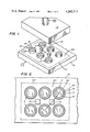
- FIG. 1 is a fragmentary perspective view of a portion of an electrolytic cell for the production of aluminum constructed in accordance with the present invention.
- FIG. 2 is a top elevational view of the electrolytic cell of FIG. 1.
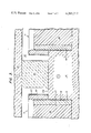
- FIG. 3 is a fragmentary cross-sectional view taken along the line 3--3 of FIG. 2, wherein the cell is heated to its operating temperature.
- FIG. 1 A preferred embodiment of an electrolytic cell for production of aluminum having cathodes 11 protected from thermal shock in accordance with the present invention is illustrated in FIG. 1.
- the portion of the cell shown in FIG. 1 is at room temperature prior to initiating start up and before any molten bath is poured into the cell chamber 12.
- the carbon anode 13 is shown elevated several inches above the cathodes 11.
- a rectangle 13a represents the shadow of the anode 13.
- Portions of the electrolytic cell not shown are similar to the cell described and illustrated in U.S. Pat. No. 4,071,420, the disclosure of which is incorporated by reference to the extent not inconsistent with the present invention.
- each cathode 11 comprises a hollow body or cylindrical sintered TiB 2 tube 14 having a height of four inches, an internal diameter of three inches, and a wall thickness of one-half inch.
- Six round holes accepting the TiB 2 tubes 14 were cut in a carbon cathode block 15 at a depth of 21/2 inches using a core drill bit of appropriate size.
- Proximal portions of the TiB 2 tubes 14 were then cemented into each annular depression and leveled at a height of 11/2 inches above the upper surface portion 15a of the cathode block 15.
- a suitable cement 16 is sold under the trade designation C-34 by Union Carbide Corporation. This cement includes particles of carbon in a resin base and provides an electrically conductive bond between the cathode block 15 and TiB 2 tubes 14.
- each cathode 11 includes a proximal portion cemented to the cathode block 15 and a distal or protruding portion extending toward the anode 13.
- the cathodes 11 are formed from hollow cylindrical bodies extending into the chamber 12 in the direction of the anode 13.
- each hollow body defines a cavity 17 open at a distal end closest the anode 13 and closed at a proximal end opposite the distal end.
- the cathodes 11 may be formed from other refractory hard substances.
- the borides, nitrides and carbides of titanium and zirconium, for example, are suitable.
- the start up method of the present invention may also be used for protecting from thermal shock anodes made of various other refractory materials including electrically conductive oxides of divalent and trivalent metals inert to the contents of the cell at its operating temperature. Examples of such oxides are CoCr 2 O 4 , TiFe 2 O 4 , CoY 2 O 4 , NiCr 2 O 4 and NiCo 2 O 4 .
- each TiB 2 tube 14 is filled by a heat conductor means, preferably a solid metal plug 18.
- the heat conductor means has a thermal conductivity greater than that of the TiB 2 tube or hollow body 14, thereby minimizing temperature differences between various locations on each hollow body.
- the metal plug 18 comprises a cylinder of an alloy of aluminum containing 33.2% copper. This alloy has a melting point of 547° C. Other alloys of aluminum having melting points in the range of about 450° to 550° C. are also suitable. Alloys of zinc, tin and magnesium with aluminum may be used instead of the Cu--Al alloy described above. Alloys that wet TiB 2 are preferred.
- the plug 18 should preferably have a melting point less than the melting temperature of aluminum (660° C.) in order to protect the cathodes 11 from thermal shock during final stages of heating. It is, of course, desirable that the plug 18 have a boiling point greater than the operating temperature of the cell.
- the metal plug 18 is inserted as a solid cylinder into the cavity 17 prior to starting up the cell.
- Each TiB 2 tube 14 is shaped to define a cylindrical cavity 17 having an inner diameter slightly greater than the outer diameter of the metal plug 18. The tube 14 therefore does not burst upon heating, even though metal of the plug 18 has a greater coefficient of thermal expansion than TiB 2 .
- the cell is provided during start up with several carbon resistor blocks 21 extending between an upper surface portion 15a of the cathode block 15 and the anode 13.
- Each resistor block 21 has transverse dimensions of two inches by two inches and has a height of 23/4 inches.
- Each of these blocks 21 acts as an auxiliary radiant heat source to supply radiant heat to the chamber 12 during the final stages of cell heat up.
- a current of at least five amps per square inch is passed through the blocks 21, thereby heating their outer surfaces to temperatures of about 2000° C. It has been found that when unprotected TiB 2 tubes 14 are exposed to radiant heat at temperatures of this magnitude, the tubes 14 may break under the stress of thermal shock.
- the TiB 2 tubes 14 are protected from thermal shock by encircling each tube 14 with a heat dispersing means or metal jacket 22.
- Each jacket 22 is at least about 1/8 inch thick, has a diameter one inch greater than the corresponding tubes 14 and is 1/2 inch higher than the tubes 14. Mild steel and stainless steel have been tried for the heat dispersing means 22, but stainless steel is superior because of its higher melting point and resistance to high temperature oxidation.
- the heat dispersing means should have a melting point at least approximating the operating temperature of the cell. When the cell is used for electrolytic production of aluminum, the heat dispersing means preferably has a melting point of greater than about 1400° C.
- the heat dispersing means should also be resistant to oxidation and structurally rigid at temperatures of about 1400° C.
- Each heat insulating means preferably comprises a generally cylindrical sleeve 23 of expanded fibrous kaolin insulating material. As shown in FIG. 3, the sleeve 23 has a thickness of about 1/2 inch, filling the gap between the metal jacket 22 and hollow TiB 2 tube 14.
- Kaowool Unifelt 3000 is sold under the trade designation Kaowool Unifelt 3000 by Babcock & Wilcox.
- Other insulating materials may be used provided they have melting points of greater than about 1400° to 1500° C., are chemically stable at temperatures of at least 2000° C. and are soluble in the cell contents or media at the operating temperature of the cell.
- the cell chamber contains a molten bath at its operating temperature that is predominantly cryolite, and the kaolin sleeve dissolves in the molten bath.
- the insulating effect should preferably be equivalent to a 1/2 inch thickness of material having a thermal conductivity less than about 0.7 BTU/(hr) (ft 2 )(°F./in). This preferred thickness may be reduced if a better insulator is used, but a greater thickness of material is desirable when thermal conductivity of the heat insulating means is increased.
- a lesser thickness of as little as 1/4 inch may be quite beneficial.
- 240 hollow TiB 2 tubes 14 were cemented to a cathode block 15 and protected from thermal shock, as shown in FIGS. 1 and 2.
- Several hundred pounds of charcoal briquettes (not shown) were distributed around the TiB 2 tubes 14 in accordance with the preheating method disclosed in Minick U.S. Pat. No. 4,146,444, issued Mar. 27, 1979.
- the anodes 13 were then placed in the cell, resting on the resistor blocks 21.
- the sides, ends and middle of the cell were filled with charcoal adjacent the anodes 13 to a depth of about five to six inches.
- the briquettes were soaked with kerosene and ignited, with air being pumped into the cell through ducts (not shown) to enhance burning.
- the ignited charcoal briquettes act as an auxiliary source of radiant heat in the initial stages of cell start up.
- the cell temperature rose to about 550° to 600° C. at a rate of about 50° C./hr.
Landscapes
- Chemical & Material Sciences (AREA)
- Engineering & Computer Science (AREA)
- Organic Chemistry (AREA)
- Electrochemistry (AREA)
- Materials Engineering (AREA)
- Metallurgy (AREA)
- Chemical Kinetics & Catalysis (AREA)
- Nanotechnology (AREA)
- Health & Medical Sciences (AREA)
- Life Sciences & Earth Sciences (AREA)
- General Health & Medical Sciences (AREA)
- Molecular Biology (AREA)
- Crystallography & Structural Chemistry (AREA)
- Electrolytic Production Of Metals (AREA)
- Investigating Or Analyzing Materials By The Use Of Ultrasonic Waves (AREA)
Priority Applications (13)
| Application Number | Priority Date | Filing Date | Title |
|---|---|---|---|
| GB7938642A GB2062862B (en) | 1979-11-08 | 1979-11-07 | Fully automatic ultrasonic flaw detection apparatus |
| US06/092,441 US4265717A (en) | 1979-11-08 | 1979-11-08 | Method and apparatus for protecting electrodes from thermal shock during start up |
| AU61640/80A AU6164080A (en) | 1979-11-08 | 1980-08-21 | Thermal shock protection for electrodes |
| CA000359022A CA1146121A (en) | 1979-11-08 | 1980-08-26 | Thermal shock protection for electrodes |
| NO803178A NO803178L (no) | 1979-11-08 | 1980-10-24 | Elektrolytisk celle. |
| DE19803040914 DE3040914A1 (de) | 1979-11-08 | 1980-10-30 | Elektrolysezelle |
| FR8023207A FR2469474A1 (fr) | 1979-11-08 | 1980-10-30 | Cellule d'electrolyse fonctionnant a temperature elevee, a electrodes protegees des chocs thermiques |
| IT50074/80A IT1133050B (it) | 1979-11-08 | 1980-11-04 | Cella elettrolitica con protezione da urto termico per gli elettrodi |
| NL8006029A NL8006029A (nl) | 1979-11-08 | 1980-11-04 | Elektrolytische cel. |
| JP15572880A JPS5675587A (en) | 1979-11-08 | 1980-11-05 | Electrolytic tank for producing metal |
| BR8007196A BR8007196A (pt) | 1979-11-08 | 1980-11-06 | Celula eletrolitica para producao de metal a uma temperatura operacional elevada |
| SE8007801A SE8007801L (sv) | 1979-11-08 | 1980-11-06 | Elektrolytisk cell |
| ES496672A ES496672A0 (es) | 1979-11-08 | 1980-11-07 | Una celda electrolitica |
Applications Claiming Priority (1)
| Application Number | Priority Date | Filing Date | Title |
|---|---|---|---|
| US06/092,441 US4265717A (en) | 1979-11-08 | 1979-11-08 | Method and apparatus for protecting electrodes from thermal shock during start up |
Publications (1)
| Publication Number | Publication Date |
|---|---|
| US4265717A true US4265717A (en) | 1981-05-05 |
Family
ID=22233229
Family Applications (1)
| Application Number | Title | Priority Date | Filing Date |
|---|---|---|---|
| US06/092,441 Expired - Lifetime US4265717A (en) | 1979-11-08 | 1979-11-08 | Method and apparatus for protecting electrodes from thermal shock during start up |
Country Status (13)
| Country | Link |
|---|---|
| US (1) | US4265717A (no) |
| JP (1) | JPS5675587A (no) |
| AU (1) | AU6164080A (no) |
| BR (1) | BR8007196A (no) |
| CA (1) | CA1146121A (no) |
| DE (1) | DE3040914A1 (no) |
| ES (1) | ES496672A0 (no) |
| FR (1) | FR2469474A1 (no) |
| GB (1) | GB2062862B (no) |
| IT (1) | IT1133050B (no) |
| NL (1) | NL8006029A (no) |
| NO (1) | NO803178L (no) |
| SE (1) | SE8007801L (no) |
Cited By (12)
| Publication number | Priority date | Publication date | Assignee | Title |
|---|---|---|---|---|
| US4339316A (en) * | 1980-09-22 | 1982-07-13 | Aluminum Company Of America | Intermediate layer for seating RHM tubes in cathode blocks |
| US4410412A (en) * | 1980-11-26 | 1983-10-18 | Swiss Aluminium Ltd. | Cathode for an electrolytic cell for producing aluminum via the fused salt electrolytic process |
| US4436598A (en) | 1983-09-28 | 1984-03-13 | Reynolds Metals Company | Alumina reduction cell |
| US4450054A (en) * | 1983-09-28 | 1984-05-22 | Reynolds Metals Company | Alumina reduction cell |
| WO1995006145A1 (en) * | 1993-08-27 | 1995-03-02 | Moen Asbjoern | Procedure and device for electrical drying and preheating of cells for electrolysis |
| WO2003062496A1 (en) * | 2002-01-24 | 2003-07-31 | Northwest Aluminum Technology | Low temperature aluminum reduction cell |
| FR2844811A1 (fr) * | 2002-09-20 | 2004-03-26 | Pechiney Aluminium | Procede de prechauffage d'une cuve pour la production d'aluminium par electrolyse |
| US20040094409A1 (en) * | 2002-01-25 | 2004-05-20 | D'astolfo Leroy E. | Inert anode assembly |
| US20050194260A1 (en) * | 2004-03-08 | 2005-09-08 | Burg James T. | Cermet inert anode assembly heat radiation shield |
| EP2688130A1 (en) | 2002-11-25 | 2014-01-22 | Alcoa Inc. | Inert anode assembly |
| CN103547710A (zh) * | 2011-05-25 | 2014-01-29 | 力拓艾尔坎国际有限公司 | 用于铝生产的电解池的干电池启动 |
| US12173419B2 (en) | 2019-08-28 | 2024-12-24 | Elysis Limited Partnership | Apparatus and method for operating an electrolytic cell |
Families Citing this family (1)
| Publication number | Priority date | Publication date | Assignee | Title |
|---|---|---|---|---|
| DE3300818C2 (de) * | 1983-01-12 | 1987-05-07 | Institut elektrosvarki imeni E.O. Patona Akademii Nauk Ukrainskoj SSR, Kiew/Kiev | Vorrichtung zur Ultraschallprüfung von Schweißnähten |
Citations (4)
| Publication number | Priority date | Publication date | Assignee | Title |
|---|---|---|---|---|
| GB1046705A (en) * | 1964-05-27 | 1966-10-26 | British Aluminium Co Ltd | Improvements in or relating to the operation of electrolytic reduction cells for theproduction of aluminium |
| US4071420A (en) * | 1975-12-31 | 1978-01-31 | Aluminum Company Of America | Electrolytic production of metal |
| US4146444A (en) * | 1978-04-10 | 1979-03-27 | Aluminum Company Of America | Method for preheating a molten salt electrolysis cell |
| US4177128A (en) * | 1978-12-20 | 1979-12-04 | Ppg Industries, Inc. | Cathode element for use in aluminum reduction cell |
Family Cites Families (1)
| Publication number | Priority date | Publication date | Assignee | Title |
|---|---|---|---|---|
| US3287247A (en) * | 1962-07-24 | 1966-11-22 | Reynolds Metals Co | Electrolytic cell for the production of aluminum |
-
1979
- 1979-11-07 GB GB7938642A patent/GB2062862B/en not_active Expired
- 1979-11-08 US US06/092,441 patent/US4265717A/en not_active Expired - Lifetime
-
1980
- 1980-08-21 AU AU61640/80A patent/AU6164080A/en not_active Abandoned
- 1980-08-26 CA CA000359022A patent/CA1146121A/en not_active Expired
- 1980-10-24 NO NO803178A patent/NO803178L/no unknown
- 1980-10-30 FR FR8023207A patent/FR2469474A1/fr active Granted
- 1980-10-30 DE DE19803040914 patent/DE3040914A1/de not_active Withdrawn
- 1980-11-04 IT IT50074/80A patent/IT1133050B/it active
- 1980-11-04 NL NL8006029A patent/NL8006029A/nl not_active Application Discontinuation
- 1980-11-05 JP JP15572880A patent/JPS5675587A/ja active Pending
- 1980-11-06 SE SE8007801A patent/SE8007801L/xx not_active Application Discontinuation
- 1980-11-06 BR BR8007196A patent/BR8007196A/pt unknown
- 1980-11-07 ES ES496672A patent/ES496672A0/es active Granted
Patent Citations (4)
| Publication number | Priority date | Publication date | Assignee | Title |
|---|---|---|---|---|
| GB1046705A (en) * | 1964-05-27 | 1966-10-26 | British Aluminium Co Ltd | Improvements in or relating to the operation of electrolytic reduction cells for theproduction of aluminium |
| US4071420A (en) * | 1975-12-31 | 1978-01-31 | Aluminum Company Of America | Electrolytic production of metal |
| US4146444A (en) * | 1978-04-10 | 1979-03-27 | Aluminum Company Of America | Method for preheating a molten salt electrolysis cell |
| US4177128A (en) * | 1978-12-20 | 1979-12-04 | Ppg Industries, Inc. | Cathode element for use in aluminum reduction cell |
Cited By (22)
| Publication number | Priority date | Publication date | Assignee | Title |
|---|---|---|---|---|
| US4339316A (en) * | 1980-09-22 | 1982-07-13 | Aluminum Company Of America | Intermediate layer for seating RHM tubes in cathode blocks |
| US4410412A (en) * | 1980-11-26 | 1983-10-18 | Swiss Aluminium Ltd. | Cathode for an electrolytic cell for producing aluminum via the fused salt electrolytic process |
| US4436598A (en) | 1983-09-28 | 1984-03-13 | Reynolds Metals Company | Alumina reduction cell |
| US4450054A (en) * | 1983-09-28 | 1984-05-22 | Reynolds Metals Company | Alumina reduction cell |
| AU567763B2 (en) * | 1983-09-28 | 1987-12-03 | Reynolds Metals Co. | Alumina reduction cell |
| WO1995006145A1 (en) * | 1993-08-27 | 1995-03-02 | Moen Asbjoern | Procedure and device for electrical drying and preheating of cells for electrolysis |
| WO2003062496A1 (en) * | 2002-01-24 | 2003-07-31 | Northwest Aluminum Technology | Low temperature aluminum reduction cell |
| US6818106B2 (en) | 2002-01-25 | 2004-11-16 | Alcoa Inc. | Inert anode assembly |
| US20040094409A1 (en) * | 2002-01-25 | 2004-05-20 | D'astolfo Leroy E. | Inert anode assembly |
| US7485215B2 (en) | 2002-09-20 | 2009-02-03 | Aluminium Pechiney | Method of pre-heating a stack for aluminium electrolysis production |
| FR2844811A1 (fr) * | 2002-09-20 | 2004-03-26 | Pechiney Aluminium | Procede de prechauffage d'une cuve pour la production d'aluminium par electrolyse |
| NO341453B1 (no) * | 2002-09-20 | 2017-11-13 | Pechiney Aluminium | Fremgangsmåte for forvarmer av et kar for aluminiumelektrolyseproduksjon |
| US20060131180A1 (en) * | 2002-09-20 | 2006-06-22 | Aluminum Pechiney | Method of pre-heating a stack for aluminium electrolysis production |
| WO2004027119A3 (fr) * | 2002-09-20 | 2004-04-22 | Pechiney Aluminium | Procede de prechauffage d'une cuve pour la production d'aluminium par electrolyse |
| RU2319792C2 (ru) * | 2002-09-20 | 2008-03-20 | Алюминиюм Пешинэ | Способ предварительного нагрева электролизера для получения алюминия электролизом |
| EP2688130A1 (en) | 2002-11-25 | 2014-01-22 | Alcoa Inc. | Inert anode assembly |
| US20080067060A1 (en) * | 2004-03-08 | 2008-03-20 | Alcoa Inc. | Cermet inert anode assembly heat radiation shield |
| US7282133B2 (en) | 2004-03-08 | 2007-10-16 | Alcoa Inc. | Cermet inert anode assembly heat radiation shield |
| US20050194260A1 (en) * | 2004-03-08 | 2005-09-08 | Burg James T. | Cermet inert anode assembly heat radiation shield |
| CN103547710A (zh) * | 2011-05-25 | 2014-01-29 | 力拓艾尔坎国际有限公司 | 用于铝生产的电解池的干电池启动 |
| US12173419B2 (en) | 2019-08-28 | 2024-12-24 | Elysis Limited Partnership | Apparatus and method for operating an electrolytic cell |
| US12203187B2 (en) | 2019-08-28 | 2025-01-21 | Elysis Limited Partnership | Apparatus and method for operating an electrolytic cell |
Also Published As
| Publication number | Publication date |
|---|---|
| DE3040914A1 (de) | 1981-05-21 |
| FR2469474A1 (fr) | 1981-05-22 |
| IT1133050B (it) | 1986-07-09 |
| GB2062862B (en) | 1984-03-14 |
| JPS5675587A (en) | 1981-06-22 |
| ES8202872A1 (es) | 1982-02-16 |
| AU6164080A (en) | 1981-05-14 |
| ES496672A0 (es) | 1982-02-16 |
| NL8006029A (nl) | 1981-06-01 |
| BR8007196A (pt) | 1981-05-12 |
| NO803178L (no) | 1981-05-11 |
| SE8007801L (sv) | 1981-05-09 |
| FR2469474B1 (no) | 1982-11-19 |
| IT8050074A0 (it) | 1980-11-04 |
| GB2062862A (en) | 1981-05-28 |
| CA1146121A (en) | 1983-05-10 |
Similar Documents
| Publication | Publication Date | Title |
|---|---|---|
| US4265717A (en) | Method and apparatus for protecting electrodes from thermal shock during start up | |
| US5284562A (en) | Non-consumable anode and lining for aluminum electrolytic reduction cell | |
| US3775091A (en) | Induction melting of metals in cold, self-lined crucibles | |
| US3028324A (en) | Producing or refining aluminum | |
| US4468300A (en) | Nonconsumable electrode assembly and use thereof for the electrolytic production of metals and silicon | |
| US3156639A (en) | Electrode | |
| US4468299A (en) | Friction welded nonconsumable electrode assembly and use thereof for electrolytic production of metals and silicon | |
| US3215615A (en) | Current conducting element for aluminum production cells | |
| US4224128A (en) | Cathode assembly for electrolytic aluminum reduction cell | |
| US4247381A (en) | Facility for conducting electrical power to electrodes | |
| JPS58213888A (ja) | アルミニウム製造用電解還元槽 | |
| US3274093A (en) | Cathode construction for aluminum production | |
| US5411611A (en) | Consumable electrode method for forming micro-alloyed products | |
| US4181584A (en) | Method for heating electrolytic cell | |
| NO163855B (no) | Analogifremgangsmaate for fremstilling av terapeutisk aktive arylcyklobutylalkylaminer. | |
| NO803793L (no) | Anode for smelteelektrolysecelle. | |
| US4450061A (en) | Metal stub and ceramic body electrode assembly | |
| NO764014L (no) | ||
| US3321392A (en) | Alumina reduction cell and method for making refractory lining therefor | |
| GB2062682A (en) | Protecting Electrodes of an Electrolytic Cell from Thermal Shock | |
| US3202600A (en) | Current conducting element for aluminum reduction cells | |
| GB1046705A (en) | Improvements in or relating to the operation of electrolytic reduction cells for theproduction of aluminium | |
| US3787300A (en) | Method for reduction of aluminum with improved reduction cell and anodes | |
| AU2003276352A1 (en) | Method for pre-heating a stack for aluminium electrolysis production | |
| US4146444A (en) | Method for preheating a molten salt electrolysis cell |
Legal Events
| Date | Code | Title | Description |
|---|---|---|---|
| STCF | Information on status: patent grant |
Free format text: PATENTED CASE |