US4257158A - Bus suspension mating fixture assembly - Google Patents
Bus suspension mating fixture assembly Download PDFInfo
- Publication number
- US4257158A US4257158A US06/024,506 US2450679A US4257158A US 4257158 A US4257158 A US 4257158A US 2450679 A US2450679 A US 2450679A US 4257158 A US4257158 A US 4257158A
- Authority
- US
- United States
- Prior art keywords
- bus
- assembly
- suspension
- recited
- mating fixture
- Prior art date
- Legal status (The legal status is an assumption and is not a legal conclusion. Google has not performed a legal analysis and makes no representation as to the accuracy of the status listed.)
- Expired - Lifetime
Links
Images

Classifications
-
- B—PERFORMING OPERATIONS; TRANSPORTING
- B62—LAND VEHICLES FOR TRAVELLING OTHERWISE THAN ON RAILS
- B62D—MOTOR VEHICLES; TRAILERS
- B62D65/00—Designing, manufacturing, e.g. assembling, facilitating disassembly, or structurally modifying motor vehicles or trailers, not otherwise provided for
- B62D65/02—Joining sub-units or components to, or positioning sub-units or components with respect to, body shell or other sub-units or components
-
- Y—GENERAL TAGGING OF NEW TECHNOLOGICAL DEVELOPMENTS; GENERAL TAGGING OF CROSS-SECTIONAL TECHNOLOGIES SPANNING OVER SEVERAL SECTIONS OF THE IPC; TECHNICAL SUBJECTS COVERED BY FORMER USPC CROSS-REFERENCE ART COLLECTIONS [XRACs] AND DIGESTS
- Y10—TECHNICAL SUBJECTS COVERED BY FORMER USPC
- Y10T—TECHNICAL SUBJECTS COVERED BY FORMER US CLASSIFICATION
- Y10T29/00—Metal working
- Y10T29/49—Method of mechanical manufacture
- Y10T29/49826—Assembling or joining
- Y10T29/49904—Assembling a subassembly, then assembling with a second subassembly
-
- Y—GENERAL TAGGING OF NEW TECHNOLOGICAL DEVELOPMENTS; GENERAL TAGGING OF CROSS-SECTIONAL TECHNOLOGIES SPANNING OVER SEVERAL SECTIONS OF THE IPC; TECHNICAL SUBJECTS COVERED BY FORMER USPC CROSS-REFERENCE ART COLLECTIONS [XRACs] AND DIGESTS
- Y10—TECHNICAL SUBJECTS COVERED BY FORMER USPC
- Y10T—TECHNICAL SUBJECTS COVERED BY FORMER US CLASSIFICATION
- Y10T29/00—Metal working
- Y10T29/53—Means to assemble or disassemble
- Y10T29/53539—Means to assemble or disassemble including work conveyor
- Y10T29/53543—Means to assemble or disassemble including work conveyor including transporting track
- Y10T29/53548—Means to assemble or disassemble including work conveyor including transporting track and work carrying vehicle
-
- Y—GENERAL TAGGING OF NEW TECHNOLOGICAL DEVELOPMENTS; GENERAL TAGGING OF CROSS-SECTIONAL TECHNOLOGIES SPANNING OVER SEVERAL SECTIONS OF THE IPC; TECHNICAL SUBJECTS COVERED BY FORMER USPC CROSS-REFERENCE ART COLLECTIONS [XRACs] AND DIGESTS
- Y10—TECHNICAL SUBJECTS COVERED BY FORMER USPC
- Y10T—TECHNICAL SUBJECTS COVERED BY FORMER US CLASSIFICATION
- Y10T29/00—Metal working
- Y10T29/53—Means to assemble or disassemble
- Y10T29/53961—Means to assemble or disassemble with work-holder for assembly
- Y10T29/53974—Means to assemble or disassemble with work-holder for assembly having means to permit support movement while work is thereon
-
- Y—GENERAL TAGGING OF NEW TECHNOLOGICAL DEVELOPMENTS; GENERAL TAGGING OF CROSS-SECTIONAL TECHNOLOGIES SPANNING OVER SEVERAL SECTIONS OF THE IPC; TECHNICAL SUBJECTS COVERED BY FORMER USPC CROSS-REFERENCE ART COLLECTIONS [XRACs] AND DIGESTS
- Y10—TECHNICAL SUBJECTS COVERED BY FORMER USPC
- Y10T—TECHNICAL SUBJECTS COVERED BY FORMER US CLASSIFICATION
- Y10T29/00—Metal working
- Y10T29/53—Means to assemble or disassemble
- Y10T29/53978—Means to assemble or disassemble including means to relatively position plural work parts
Definitions
- U.S. Pat. No. 3,827,137 to T. C. Schubach discloses and claims a method of manufacturing a transit vehicle by completing, in individual jigs, sub-assemblies of a transit vehicle, including a floor assembly, side wall assemblies, a roof assembly, and a front end assembly, and then assembling these completed sub-assemblies to provide a substantially completed vehicle.
- the present invention is based on the general concepts of the two patents described above, but goes beyond them in providing a bus suspension mating fixture assembly into which the body shell of the transit vehicle is carried along overhead support rails prior to its being lowered onto the properly positioned front and rear bus suspension assemblies.
- the novel bus suspension mating fixture assembly plays an essential role in the assembly of a transit vehicle such as a bus.
- the stage at which the bus is in its assembly process when it reaches the novel bus suspension mating fixture assembly is that of a completed upper body of the bus.
- the floor, the roof, both side walls, and the front and rear walls of the body have all been assembled together.
- the interior of the bus has also been completely finished and the only thing lacking is the front and rear suspension assemblies.
- the assembled bus body is brought into the mating fixture assembly in the state above described by having it travel along the overhead rail conveyor assembly. Once in its proper position therein, a shuttle platform carrying the front and rear suspension assemblies in their properly spaced positions is drawn laterally into position within the confines of the bus body overhead support assembly directly beneath the bus body being suspended from the overhead rail conveyor assembly. Next the overhead support rails are lowered to properly position the bus body onto the front and rear bus suspension assemblies. After all attachments have been secured between the bus body and the suspension assemblies, the lift-bar cradles have their cables secured between the lift-bar cradles and the overhead support rail. The completely assembled bus is then raised upwardly as a complete unit a sufficient distance to allow the shuttle platform to be withdrawn from thereunder.
- the completely assembled bus is then lowered to ground level, started up, and driven out of the lift-bar cradles and out of the vehicle mating fixture assembly. At this point the lift-bar cradles are removed from a position within the bus body overhead support assembly and the whole operation of assembling a new bus can be started again.
- FIG. 1 is a perspective schematic illustration of the production flow process for assembling the bus body into a unitary member from a plurality of sub-assemblies;
- FIG. 2 is a perspective schematic view illustrating how the completed bus body is transferred to the bus suspension mating fixture assembly
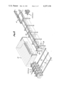
- FIG. 2a is a perspective view illustrating the novel bus suspension mating fixture assembly
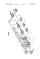
- FIG. 3 is a schematic perspective view illustrating the sequence of operations that are involved in taking the front bus suspension assembly and the rear bus suspension assembly to the bus suspension mating fixture assembly;
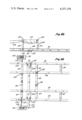
- FIG. 4a is a side elevation view of the forward portion of the bus suspension shuttle assembly
- FIG. 4b is a side elevation view of the middle portion of the bus suspension shuttle assembly
- FIG. 4c is a side elevation view of the rear portion of the bus suspension shuttle assembly
- FIG. 5a is a top plan view of FIG. 4a
- FIG. 5b is a top plan view of FIG. 4b.
- FIG. 5c is a top plan view of FIG. 4c.
- a traveling collector such as described in U.S. Pat. No. 4,033,033 is generally designed at numeral 8.
- collector 8 travels back and forth laterally along rails 9.
- floor sub-assembly 10 is loaded into the collector in its proper position.
- collector 8 travels to station B, where roof sub-assembly 12 is loaded therein, in its proper position.
- the collector travels to station C where roadside sidewall sub-assembly 14 is loaded into the collector.
- the collector then travels to station D where the curbside sidewall sub-assembly is loaded therein.
- overhead rail conveyor assembly 22 is seen to have a plurality of upright side beams 24 with transverse top beams 25 having their opposite ends attached to the top of upright side beams 24. Suspended from transverse top beams 25 are longitudinal overhead support rails 23. Continuing along the bus assembly process, the bus body is transported along overhead support rails 23 to station I where bus suspension mating fixture assembly 30 is found.
- bus suspension mating fixture assembly 30 is illustrated in more detail. It is at this station that the front and rear bus suspension assemblies are attached to the under side of the bus body, thus completing the assembly of the bus. The structure of bus suspension mating fixture assembly 30 will be described in detail later.
- Front bus suspension assembly 32 is initially taken to staging area 33 and bus rear suspension assembly 34 is initially taken to staging area 35. From this point rear suspension assembly 35 is taken to station H where its wheels are positioned within aligning blocks 36. Next front suspension assembly 32 is taken to station H and its wheels positioned within aligning blocks 37. At this point attaching members 41 of lifting jig 38 are secured to the respective front and rear suspension assemblies. Lifting jig 38 has a longitudinal beam 39 and two transverse beams 40 at its opposite ends. Extending downwardly from the lifting jig are attaching members 41 mentioned previously.
- Lifting chains 44 are attached at the opposite ends of transverse beams 40 and intermediate their ends they pass through a hook 45 extending downwardly from the bottom of cable 46. Cables 46 are attached at their top ends to a pair of overhead cranes 48 that carry the lifting jig to station I where the front and rear bus suspension assemblies are unloaded onto shuttle platform 54 of the bus suspension shuttle assembly 50.
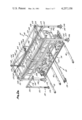
- the structure of shuttle platform 54 will be discussed by referring to FIGS. 4 and 5 of the drawings.
- the shuttle platform is in the form of a frame having a plurality of laterally spaced longitudinal beams 56 that are interconnected by transversely extending major crossbeams 58 and minor crossbeams 60.
- Crossplates 62 have their opposite ends welded to the top of a pair of spaced longitudinal beams 56 and these crossplates 62 provide a mounting surface for front wheel locator units 64.
- the top part of front wheel locator unit 64 is a wheel guideplate 65 that aids in directing the bus tire 67 into its proper position.
- the lift-bar cradles later provide a lifting structure for the wheels of the bus when completely assembled.
- Bus front suspension assembly locators 68 extend upwardly from the top of minor crossbeam 60. They consist of tubular supports 70 having a bracket 72 mounted at their top upon which crossbeam 69 of bus front suspension assembly 32 rests. Threaded rods 73 pass through brackets 72 and have a handle 74 for tightening the threaded rod against the frame crossbeam 69 for securing it in position.
- Bus front suspension assembly supports 80 are mounted forwardly of tires 67 and extend upwardly from minor crossbeams 60. These supports 80 comprise a tubular member 81 which has mounted at its top an upright plate 77 and an upright plate 78 that capture between them another frame crossbeam member 69 of the front suspension assembly.
- the most forwardly positioned bus front suspension assembly support 80 has a tubular post 81 with a plate 82 positioned at its top which supports the bus bumper 83.
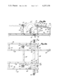
- roller bracket mounting plates 90 Mounted on the underside of shuttle platform 54 are a plurality of roller bracket mounting plates 90. Roller brackets 91 are mounted on their bottom surface and have rollers 92 attached thereto. As the shuttle platform 54 is moved inwardly into position and outwardly from beneath bus body overhead support assembly 140, rollers 92 travel along rail plates 93. At the opposite ends of each of the roll plates 93 are found shock absorber units 94 secured to mounting brackets 95.
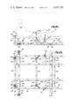
- FIGS 4c and 5c the rear portion of shuttle platform 54 will be described. It is on this portion that bus rear suspension assembly 34 is positioned.
- the basic framework for the shuttle platform 54 has been described previously and extending upwardly therefrom are a pair of laterally spaced rear locator assemblies 100. These rear locator assemblies have a post 101 having a bracket 102 mounted at their top. Post brace 103 adds rigidity to the rear locator assembly structure.
- the wheels of the rear suspension assembly are guided into wheel locator units 64 by wheel guide plates 65.
- the rear suspension assembly has an engine support frame 105 upon which is mounted engine 106.
- engine support frame 105 rests on bracket 102, and the rear portion of the engine support frame rests on rear support stand 110 which is comprised of a tubular support 111 having a bracket 112 mounted at its top through which extend threaded rods 113 and 115.
- the threaded rods can be brought into engagement with transverse frame member 107 of the rear suspension assembly for holding it in its proper position.
- the forward portion of the rear suspension assembly 34 has a tongue 118 whose front end is bolted to fuel tank bolster 119 (see FIGS. 4b and 5b).
- Fuel tank bolster 119 is positioned and supported by locator assemblies 120. These locator assemblies consist of post members 121 extending upwardly from the crossbeam members of the shuttle platform. At the top of the post 121 are found guide members 122 for directing the fuel tank bolster into its proper position.
- shuttle platform 54 Mounted transversely beneath the central portion of shuttle platform 54 is a guide plate 125. It interacts with guide rollers 127 that are attached to mounting plates 126 secured to the underside of the shuttle platform 54. This structure ensures that the shuttle platform will maintain its alignment as it is caused to travel into position beneath the overhead support assembly 140 and back outwardly to its loading position at its other extreme position.
- the structure for moving the shuttle platform 54 between its loading position and its unloading position consists of a pair of power winches 130 mounted on base plates 131 on opposite lateral sides of shuttle platform 54. Each of these power winches have a cable 132 with a ring loop 133 at its end that is secured to a cable attaching bracket assembly 134 mounted upon the outer surface of longitudinal beams 56.
- the bus body overhead support assembly is best illustrated in FIG. 2a.
- the overhead support assembly 140 has a pair of laterally spaced top longitudinal beams 142 whose opposite ends are attached to transverse top beam members 143. Supporting this structure are a plurality of upright side beams 144 that are mounted on base plates 146 and have ribbed brace members 147 to give them additional structural support. Lower longitudinal beams 148 are also connected between upright side beam 145 and along with upright brace member 149 and diagonal brace members 150 structurally reinforce the overhead support assembly 140.
- Longitudinal support rails 23 have transverse members 155 attached to them.
- the plurality of jack screw units 154 pass through the outer extremities of transverse members 155 and have their opposite ends secured in support brackets 156 at the bottom and in gear box units 158 at their top.
- the overhead support rails can be raised and lowered through a predetermined range as required.
- the jack screw units operate simultaneously they are connected together by transverse drive shafts 159, gearbox units 160, longitudinal drive shafts 162, gearbox units 163, transverse drive shaft 164, gear reducer 165 and are ultimately driven by motor 166.
- the structure for supporting the bus body shell as it is transported into the overhead support assembly 140 consists of a pair of laterally spaced longitudinal overhead bus support beams 167 having vertical support arms 168 extending upwardly therefrom. Rollers attached at the top of the support arms 168 travel along the overhead support rails 23.
- a plurality of longitudinally spaced support arms 169 extend inwardly from the overhead bus support beams 167 and are captured beneath structure of the bus body where the sidewalls are attached to the top unit. In this manner the bus body can be taken out of collector 8 after it has been assembled from its sub-assemblies and hung by its top structure by longitudinal overhead bus support beams 167.
- the bus body is then conveyed into the bus body overhead support assembly at which time the shuttle platform loaded with both the front and rear bus suspension assemblies is slid into position beneath the bus body.
- the bus body is lowered a predetermined distance so that it may be secured to the bus suspension assemblies.
- cables are attached to the lift-bar cradles and the assembled bus is raised upwardly a predetermined distance.
- the shuttle platform is withdrawn from beneath the completely assembled bus after which time the bus is lowered to ground level.
- the engine is then started and the bus is driven out through the end of the overhead support assembly 140. The last step would be to remove the lift-bar cradles by the use of the overhead lift assemblies 172.
- Winches 180 are used to pick up the lift-bar cradle units so that they may be returned to the top surface of shuttle platform 54. At this point the assembly of a new bus will start all over again.
Abstract
Description
Claims (17)
Priority Applications (1)
| Application Number | Priority Date | Filing Date | Title |
|---|---|---|---|
| US06/024,506 US4257158A (en) | 1979-03-28 | 1979-03-28 | Bus suspension mating fixture assembly |
Applications Claiming Priority (1)
| Application Number | Priority Date | Filing Date | Title |
|---|---|---|---|
| US06/024,506 US4257158A (en) | 1979-03-28 | 1979-03-28 | Bus suspension mating fixture assembly |
Publications (1)
| Publication Number | Publication Date |
|---|---|
| US4257158A true US4257158A (en) | 1981-03-24 |
Family
ID=21820939
Family Applications (1)
| Application Number | Title | Priority Date | Filing Date |
|---|---|---|---|
| US06/024,506 Expired - Lifetime US4257158A (en) | 1979-03-28 | 1979-03-28 | Bus suspension mating fixture assembly |
Country Status (1)
| Country | Link |
|---|---|
| US (1) | US4257158A (en) |
Cited By (11)
| Publication number | Priority date | Publication date | Assignee | Title |
|---|---|---|---|---|
| US4371303A (en) * | 1980-12-19 | 1983-02-01 | Acf Industries, Incorporated | Railway car fabrication facility |
| US5167065A (en) * | 1990-08-13 | 1992-12-01 | Fuji Jukogyo Kabushiki Kaisha | Wheel attachment aid apparatus in automobile assembly line |
| US6308404B1 (en) * | 1999-07-12 | 2001-10-30 | Daimlerchrysler Corporation | Apparatus and method for lifting two axles onto a vehicle chassis |
| EP1375318A2 (en) * | 2002-06-17 | 2004-01-02 | Trenkamp & Gehle GmbH | Sequential rack |
| ES2246617A1 (en) * | 2003-01-03 | 2006-02-16 | Schmitz Cargobull, S.A. | Installation for assembling axis of tow/semitrailer, has car subframe provided with large stone benches to support axes, and tracks provided in parallel to large stone benches, where tracks are perpendicular to limited zone between lifts |
| WO2009132363A1 (en) * | 2008-04-22 | 2009-10-29 | Singh, Rene | Jig for the manufacture of bus frames |
| WO2010004147A1 (en) * | 2008-07-10 | 2010-01-14 | Renault S.A.S. | Motor vehicle assembly line and method of assembling a motor vehicle |
| WO2012084087A1 (en) * | 2010-12-23 | 2012-06-28 | Daimler Ag | Method for fitting motor vehicle suspension systems |
| CN104085460A (en) * | 2014-07-16 | 2014-10-08 | 常州黄海汽车有限公司 | Passenger car assembly method and passenger car assembly line |
| US10465393B1 (en) * | 2017-12-20 | 2019-11-05 | Jared Bill Bradford | Apparatus, system and method for panelizing and installing wall and roof panels |
| CN112444361A (en) * | 2019-09-05 | 2021-03-05 | 郑州宇通客车股份有限公司 | Passenger car framework joint fixing tool and passenger car framework joint rigidity detection device |
Citations (2)
| Publication number | Priority date | Publication date | Assignee | Title |
|---|---|---|---|---|
| US2571572A (en) * | 1947-03-10 | 1951-10-16 | David L Harmon | Hoist for removing and installing springs on buses, trucks, and the like |
| US4033033A (en) * | 1976-02-23 | 1977-07-05 | Rohr Industries, Inc. | Bus manufacturing mechanism and method |
-
1979
- 1979-03-28 US US06/024,506 patent/US4257158A/en not_active Expired - Lifetime
Patent Citations (2)
| Publication number | Priority date | Publication date | Assignee | Title |
|---|---|---|---|---|
| US2571572A (en) * | 1947-03-10 | 1951-10-16 | David L Harmon | Hoist for removing and installing springs on buses, trucks, and the like |
| US4033033A (en) * | 1976-02-23 | 1977-07-05 | Rohr Industries, Inc. | Bus manufacturing mechanism and method |
Cited By (18)
| Publication number | Priority date | Publication date | Assignee | Title |
|---|---|---|---|---|
| US4371303A (en) * | 1980-12-19 | 1983-02-01 | Acf Industries, Incorporated | Railway car fabrication facility |
| US5167065A (en) * | 1990-08-13 | 1992-12-01 | Fuji Jukogyo Kabushiki Kaisha | Wheel attachment aid apparatus in automobile assembly line |
| US6308404B1 (en) * | 1999-07-12 | 2001-10-30 | Daimlerchrysler Corporation | Apparatus and method for lifting two axles onto a vehicle chassis |
| EP1375318A2 (en) * | 2002-06-17 | 2004-01-02 | Trenkamp & Gehle GmbH | Sequential rack |
| EP1375318A3 (en) * | 2002-06-17 | 2004-09-08 | Trenkamp & Gehle GmbH | Sequential rack |
| ES2246617A1 (en) * | 2003-01-03 | 2006-02-16 | Schmitz Cargobull, S.A. | Installation for assembling axis of tow/semitrailer, has car subframe provided with large stone benches to support axes, and tracks provided in parallel to large stone benches, where tracks are perpendicular to limited zone between lifts |
| WO2009132363A1 (en) * | 2008-04-22 | 2009-10-29 | Singh, Rene | Jig for the manufacture of bus frames |
| FR2933668A1 (en) * | 2008-07-10 | 2010-01-15 | Renault Sas | ASSEMBLY LINE FOR A MOTOR VEHICLE AND METHOD FOR ASSEMBLING A MOTOR VEHICLE |
| WO2010004147A1 (en) * | 2008-07-10 | 2010-01-14 | Renault S.A.S. | Motor vehicle assembly line and method of assembling a motor vehicle |
| WO2012084087A1 (en) * | 2010-12-23 | 2012-06-28 | Daimler Ag | Method for fitting motor vehicle suspension systems |
| CN103282268A (en) * | 2010-12-23 | 2013-09-04 | 戴姆勒股份公司 | Method for fitting motor vehicle suspension systems |
| CN103282268B (en) * | 2010-12-23 | 2016-03-23 | 戴姆勒股份公司 | For installing the method for automobile suspension system |
| US9434432B2 (en) | 2010-12-23 | 2016-09-06 | Daimler Ag | Method for fitting motor vehicle suspension systems |
| CN104085460A (en) * | 2014-07-16 | 2014-10-08 | 常州黄海汽车有限公司 | Passenger car assembly method and passenger car assembly line |
| CN104085460B (en) * | 2014-07-16 | 2017-12-12 | 北汽(常州)汽车有限公司 | Car assembly line |
| US10465393B1 (en) * | 2017-12-20 | 2019-11-05 | Jared Bill Bradford | Apparatus, system and method for panelizing and installing wall and roof panels |
| CN112444361A (en) * | 2019-09-05 | 2021-03-05 | 郑州宇通客车股份有限公司 | Passenger car framework joint fixing tool and passenger car framework joint rigidity detection device |
| CN112444361B (en) * | 2019-09-05 | 2022-10-28 | 宇通客车股份有限公司 | Passenger car framework joint fixing tool and passenger car framework joint rigidity detection device |
Similar Documents
| Publication | Publication Date | Title |
|---|---|---|
| US4031982A (en) | Device for mounting chassis details onto an automobile body | |
| US4257158A (en) | Bus suspension mating fixture assembly | |
| US4033033A (en) | Bus manufacturing mechanism and method | |
| JPS61166740A (en) | Automobile transport car with independent support structure exclusive for each axle | |
| US3743120A (en) | Vehicle with self-contained load transfer system | |
| CN106514254A (en) | Suspended type motorcycle frame assembly assembling system and method | |
| JP4397716B2 (en) | Heavy object placement method and system | |
| US1750130A (en) | Handling and assembling automobile bodies | |
| CN109532620A (en) | Land commutative case automobile and handling method | |
| US1824369A (en) | Vehicle for transporting automobiles or the like | |
| CN113530575B (en) | Arch frame installation trolley for tunnel multi-work construction | |
| CN106945753B (en) | Device and method for combining axle and chassis of semitrailer | |
| CN214647907U (en) | Oil pipe transport vehicle capable of automatically loading pipes from two sides | |
| JPH01101277A (en) | Welding machine for automobile body | |
| CN216805240U (en) | Motorcycle loading and unloading device | |
| CN217079894U (en) | Multifunctional automobile carrier and three-dimensional parking equipment using same | |
| CN217513117U (en) | Purlin car device and go up unloading system | |
| CN216401596U (en) | Automatic bumper system of tearing open | |
| CN215398400U (en) | Beam loading trolley device | |
| SU1765049A1 (en) | Tractor driver cab | |
| CN211541212U (en) | Rigid lifting shaft heavy truss robot | |
| CN214293084U (en) | War chariot assembling platform | |
| CN110846952B (en) | Work apparatus and control method for work apparatus | |
| JPH0259278B2 (en) | ||
| JPH0543552B2 (en) |
Legal Events
| Date | Code | Title | Description |
|---|---|---|---|
| AS | Assignment |
Owner name: GAC ACQUISITION CORPORATION, 2395 HURON PKWY., ANN Free format text: ASSIGNMENT OF ASSIGNORS INTEREST.;ASSIGNOR:GRUMMAN FLEXIBLE CORPORATION;REEL/FRAME:004160/0656 Effective date: 19830627 |
|
| AS | Assignment |
Owner name: PITTSBURGH NATIONAL BANK Free format text: ASSIGNMENT OF ASSIGNORS INTEREST;ASSIGNOR:FLXIBLE CORPORATION, THE;REEL/FRAME:006585/0842 Effective date: 19920715 |
|
| AS | Assignment |
Owner name: FLXIBLE CORPORATION, THE, OHIO Free format text: RELEASE;ASSIGNOR:PNC BANK, NATIONAL ASSOCIATION, F/K/A PITTSBURGH NATIONAL BANK;REEL/FRAME:008574/0105 Effective date: 19961009 Owner name: UNIVERSAL COACH PARTS, INC., ILLINOIS Free format text: ASSIGNMENT OF ASSIGNORS INTEREST;ASSIGNOR:FLXIBLE CORPORATION, THE;REEL/FRAME:008559/0125 Effective date: 19961025 |