US4249453A - Fluidic motor actuator - Google Patents
Fluidic motor actuator Download PDFInfo
- Publication number
- US4249453A US4249453A US05/952,029 US95202978A US4249453A US 4249453 A US4249453 A US 4249453A US 95202978 A US95202978 A US 95202978A US 4249453 A US4249453 A US 4249453A
- Authority
- US
- United States
- Prior art keywords
- fluid
- gear
- motor
- pressure
- control system
- Prior art date
- Legal status (The legal status is an assumption and is not a legal conclusion. Google has not performed a legal analysis and makes no representation as to the accuracy of the status listed.)
- Expired - Lifetime
Links
Images


Classifications
-
- F—MECHANICAL ENGINEERING; LIGHTING; HEATING; WEAPONS; BLASTING
- F15—FLUID-PRESSURE ACTUATORS; HYDRAULICS OR PNEUMATICS IN GENERAL
- F15B—SYSTEMS ACTING BY MEANS OF FLUIDS IN GENERAL; FLUID-PRESSURE ACTUATORS, e.g. SERVOMOTORS; DETAILS OF FLUID-PRESSURE SYSTEMS, NOT OTHERWISE PROVIDED FOR
- F15B9/00—Servomotors with follow-up action, e.g. obtained by feed-back control, i.e. in which the position of the actuated member conforms with that of the controlling member
- F15B9/02—Servomotors with follow-up action, e.g. obtained by feed-back control, i.e. in which the position of the actuated member conforms with that of the controlling member with servomotors of the reciprocatable or oscillatable type
- F15B9/08—Servomotors with follow-up action, e.g. obtained by feed-back control, i.e. in which the position of the actuated member conforms with that of the controlling member with servomotors of the reciprocatable or oscillatable type controlled by valves affecting the fluid feed or the fluid outlet of the servomotor
- F15B9/12—Servomotors with follow-up action, e.g. obtained by feed-back control, i.e. in which the position of the actuated member conforms with that of the controlling member with servomotors of the reciprocatable or oscillatable type controlled by valves affecting the fluid feed or the fluid outlet of the servomotor in which both the controlling element and the servomotor control the same member influencing a fluid passage and are connected to that member by means of a differential gearing
-
- F—MECHANICAL ENGINEERING; LIGHTING; HEATING; WEAPONS; BLASTING
- F15—FLUID-PRESSURE ACTUATORS; HYDRAULICS OR PNEUMATICS IN GENERAL
- F15B—SYSTEMS ACTING BY MEANS OF FLUIDS IN GENERAL; FLUID-PRESSURE ACTUATORS, e.g. SERVOMOTORS; DETAILS OF FLUID-PRESSURE SYSTEMS, NOT OTHERWISE PROVIDED FOR
- F15B9/00—Servomotors with follow-up action, e.g. obtained by feed-back control, i.e. in which the position of the actuated member conforms with that of the controlling member
- F15B9/14—Servomotors with follow-up action, e.g. obtained by feed-back control, i.e. in which the position of the actuated member conforms with that of the controlling member with rotary servomotors
Definitions
- Pneumatic actuators such as disclosed in U.S. Pat. No. 3,209,537 which provides a rotational output in response to a limited input signal are well known in the art of control mechanisms.
- the actuator or the present invention is of the continuous rotational category and is to be distinguished from those actuators such as disclosed in U.S. Pat. No. 3,486,518 which provides a rotational output in discrete steps and the continuous rotational actuator which uses a hydraulic servo mechanism to direct the position of the pneumatic supply control valve.
- the present invention relates to a fluidic control system for a motor which produces a continuous, directional, and specific angular output from a given input signal.
- the fluidic control system which accepts either angular or linear input motion, utilizes a direct drive mechanical servo to control a rotary plate directional control valve in order to direct a supply of fluid to motor to thereby provide a desired rotational output.
- the direct mechanical servo is a combination of a compound epicyclic gear train which receives a feedback position signal from the motor and an intermittent motion gear mechanism which directly engages the control valve.
- the compound epicyclic gear train allows the input motion and feedback position signal to act independently and/or simultaneously of one another to corresponding position the control valve signal to allow the required fluid to be communicated to the motor.
- Motor gear mechanism directs the position of the control valve and restrains the control valve in its last directed position against the effects of external forces.
- the intermittent motion gear mechanism generally relates to the family of limited engagement mechanisms known as "geneva lock" mechanism such as disclosed in U.S. Pat. Nos. 2,566,945 and 4,013,964, however, these prior art devices were not suitable for the operational environment of applicants' actuator.
- Applicants' intermittent motion gear mechanism is an improvement over such "geneva lock” mechanisms and directs the position of the control valve only between predetermined angular positions whereby the control valve opens and reaches a fully open position only for a predetermined input. An input greater than this predetermined amount has no further affect on the valve's position but sets the mechanical servo for the desired output.
- the feedback position signal from the motor acts through the compound epicyclic gear train and the intermittent motion gear mechanism to move the control valve to a null position when the desired output is reached.
- the present invention further includes a fluid regulator which receives a variable operational signal from the motor to regulate the pressure of the fluid supplied to control valve as a function of the differential between the pressure of the supply fluid and the exhaust from the motor.
- Another object of the present invention is to provide a motor with a regulator that limits the output torque of the motor.
- FIG. 1 is a block diagram of a control system for a motor assembly made according to the principles of this invention
- FIG. 2 is a schematic illustration of the mechanical elements of the present invention
- FIG. 3 is a detailed schematic illustration of a direct mechanical servo illustrating the relationship of a compound epicyclic gear train and the intermittent motion gear mechanism through which an input signal is transmitted to operate a control valve regulating an operational fluid supplied to the motor;
- FIG. 4 is an exploded view illustrating the intermittent motion gear mechanism of the present invention in the disengaged position
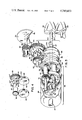
- FIG. 5 is a sectional view of the motor actuator showing a flow path for an operational fluid.
- numeral 10 generally designates the motor actuator which can be used in a gas turbine engine environment for positioning and controlling various aircraft engine functions such as the engine nozzle area, guide vanes, aircraft air foils or inlet area.
- the actuator 10 responds to an operational input, such as a request for a change in speed of the aircraft or one of the many functions performed by a turbine engine control system, to control the communication of a source of fluid under pressure to motor elements 48 and 50 of motor assembly 24.
- the fluid under pressure acts on the motor elements 48 and 50 to rotate the same and produce an output to meet the operational input request.
- the operational input which can either be linear or angular motor transmitted through belt 12, may be given a power boost through a servo-power assembly 18 shown in FIG. 2 in order to deliver sufficient mechanical force to operate the remainder of the actuator.
- the servo-power assembly 18 is adapted to transmit angular mechanical motion to a direct mechanical servo assembly 20.
- the mechanical servo assembly 20 is responsive to both the mechanical motor of the servo power assembly 18 and a feedback signal which represents the work being performed by the motor elements 48 and 50.
- the rotary output of the mechanical servo assembly 20 positions a control valve assembly 22 through linkage or shaft 58 to control the flow of fluid in conduit 14 to and from the motor assembly 24 along flow passage or conduits 26 or 28.
- the position of the control valve assembly 22 determines which flow passage 26 or 28 is the supply conduit and which is exhaust conduct. For example, when flow passage 28 is the supply conduit, as shown in FIG. 5, flow passage 26 is the exhaust conduit through which fluid from motor elements 48 and 50 is transmitted to the surrounding environment via passage 27 and conduit 25.
- a pressure regulator assembly 30 is located in conduit 14 upstream of the control valve assembly 22.
- Chamber 32 of the pressure regulator assembly 30 receives a first input signal from supply conduit or chamber 35 located in conduit 14 conduit or passage 36.
- the first input signal represents the fluid pressure in the fluid in chamber 35 after passing through orifice 138.
- Chamber 32 receives a second input signal through conduit 34.
- the second input signal represents the fluid pressure of the regulate fluid supply after passing through control valve assembly 22 but before operating the motor elements 48 and 50.
- the second input signal is a reference signal which varies in a direct relation to the flow of fluid through the motor elements 48 and 50. For example, when motor elements 48 and 50 are freely rotating the pressure level of the fluid in the supply conduit is lower than when the motor elements 48 and 50 are stationary or laboring under a load.
- conduit 34 is similarly alternately connected to the regulated fluid supply through a select high pressure valve assembly 42.
- the select high pressure valve assembly 42 includes a poppet valve member 43 and valve seat members 45 and 47.
- Valve seats 45 and 47 have passages 53 and 49 therethrough connected to a cross bore 51 for communicating fluid from conduit 102 coming from flow passage 26 and conduit 106 coming from passage 26 to passage 110.
- the poppet valve member 43 which is located in the cross bore 51 reacts to a predetermined pressure difference between the pressure of the fluid supplied to the motor elements 48 and 50 and the pressure of the fluid as it is exhausted to the surrounding environment through conduit 25 by moving toward whichever seat 45 or 47 is connected to the exhaust for the fluid from motor elements 48 and 50.
- the higher pressure of the operational fluid supplied to the motor elements 48 and 50 (the second input signal) is always communicated to conduit 34 for transmission to face 128 of piston 129.
- the fluid pressure of the supply fluid in chamber 35 is communicated to and acts on face 128 of piston 129.
- the second input signal is always less than the first input signal and a regulator pressure differential is created across piston 129.
- the regulator pressure differential reaches a predetermined value, the resulting force on piston 129 overcomes spring 126 and orifice member 136 attached to piston 129 is moved toward seat 137 to change the flow rate through orifice 138.
- the regulator pressure differential changes to allow spring 126 to position the orifice member 136 a corresponding amount to match the operation input requirement with the output of the motor assembly 24.
- a torque limiter assembly 44 connected to the regulator assembly 30 protects the motor assembly 24 and any system it controls from a situation wherein the output of motor elements 48 and 50 delivers a torque which could damage the system.
- the torque limiter assembly 44 as shown in FIG. 1 and 5, includes a housing with a bore 11.
- the housing has an inlet port connecting bore 111 to conduit 110 coming from the select high valve 42 and an outlet port connecting bore 111 to conduit 34.
- Bore 111 is directly connected to conduits 26 and 28 by conduit extensions 104 and 114 of passages or conduits 106 and 102, respectively.
- a first pressure responsive limiter valve 124 located in extension conduit 104 monitors the fluid pressure in conduit 26 and a second limiter valve 120 located in extension conduit 114 monitors the fluid pressure in conduit 28.
- Pressure limiter valve 124 is biased by spring 122 toward seat 121 and pressure limiter valve 120 is biased by spring 123 toward seat 116 to normally prevent communication from bore 111 to either extension conduit 104 or 114.
- the motor elements 48 and 50 experience a decrease in rotational speed. This decrease in speed causes an increase in the inlet fluid pressure and a decrease in the exhaust fluid pressure.
- the increase in the inlet fluid pressure is communicated through the select high valve 42, into bore 111 of the torque limiter 44 to create a pressure differential across the pressure limiter 120 or 124 then connected to the exhaust fluid pressure.
- Motor elements 48 and 50 intermesh and rotate toward each other under the influence of the fluid pressure of the supply fluid from control valve assembly 22 to provide shafts 38 and 40 with an operational output torque force responsive of an input signal supplied to the servo power assembly 18.
- the servo power assembly 18, as shown in FIG. 2, has a drive gear member 17 which receives a rotational torque from pulley 15.
- Drive gear member 17 is connected to gear 46 on shaft 47 through a rack 19 attached to a dual piston assembly.
- fluid from a source may be supplied to either piston 200 or piston 202 to amplify the input motion or operational input signal sufficiently to operate the mechanical servo 20.
- the mechanical servo 20 includes a compound epicyclic gear train 62 and an intermittent motion gear assembly 64 through which motion is transmitted from gear 46 to shaft 58 of the control valve assembly 22.
- the compound epicycle gear train 62 includes nine gears made up of the following: an input ring gear 66, an output ring gear 68, a sun gear 70, a first set of planetary gears 72, and a second set of planetary gears 74.
- Shaft 47 is fixed to the input ring gear 66 to provide a direct input from drive gear 46 to the first set of planetary gears 72, 74' and 72".
- the first set of planetary gears 72, 72' and 72" are located on corresponding shafts 76, 76' and 76".
- Shafts 76, 76' and 76" are fixed on a bearing plate 78 located inside of input ring gear 66.
- Shaft 23 which is connected to motor element 48 extends through bearing wall 87.
- the first and second planetary gears 72, 72' and 72", and 74, 74', and 74" only differ from each other by the number of teeth thereon which engage the input ring gear 66 and the output ring gear 68.
- the angular rotation of output ring gear 68 is different than the angular rotation of either the input ring gear 66 or sun gear 70.
- an input from drive gear 46 rotates the input ring gear 66 in a direction indicated by the arrow of FIG. 3.
- planetary gears 72, 72' and 72" rotates on shafts 76, 76' and 76" and at the same time rotate about sun gear 70.
- the intermittent motion gear assembly 64 includes section gear 82, gears 84 and 86, cam member 88, and four rollers 90, 90', 90" and 90'". As shown in FIG. 2, the sector gear 82 and cam member 88 are part of the output ring gear 68; however, it is not necessary that the entire member be formed as a single structure as long as the sector gear 82, ring gear 63 and cam member 88 rotate together.
- rollers 90 and 90' rotate on shafts 98 and 98' while peripheral surface 100 holds teeth 91 on gear 86 in engagement with gear 60.
- the engagement of both rollers 90 and 90' with peripheral surface 100 hold gear 86 in a stationary position.
- roller 90' enter recess 96 to synchronize the engagement of teeth 94 with the teeth on gear 84 to insure proper meshing.
- Rotation of gear 60 provides shaft 58 with an operational input for rotating plates 54 and 56 with respect to apertures or air passages 65, 67, 69 and 71 in walls 62 and 63 of the housing for the control valve assembly 22.
- a divider 73 separate passage 65 from passage 67 in wall 62 and passage 69 from passage 71 in wall 63 to estabish a first flow path between passage 69, conduit 28, motor assembly 29, conduit 26 and passage 67 and a second flow path between passage 65, conduit 26, motor assembly 24, conduit 28 and passage 71.
- the plates 54 and 56 which have slots 55 and 57 located thereon, are fixed to shaft 58 such that slots 55 and 57 are located over the walls 62 and 63 when roller 90 is aligned with the center tooth on section gear 82.
- the size of opening created between the edge of slots 55 and 57 on the plates 54 and 56 and the passages 65, 67, 69 and 71 as shaft 58 is rotated in response to an input signal supplied to pulley 15 controls the direction and the quantity of fluid supplied to motor assembly 24 for developing a resulting output force.
- Pully 15 rotates in response to an operational input signal transmitted through a belt or linkage member 12.
- the input signal to pully 15 causes a clockwise rotation thereof
- the fluid flow and gear rotation resulting therefrom to operate the actuator 10 is indicated by arrows in FIGS. 2, 3 or 4.
- pully 15 rotates in a counterclockwise direction the operation of the actuator 10 is the same; however, the rotations of the gears and flow of fluid are reversed. Therefore, in this detailed description, actuator 10 is only described when pully 15 rotated in a clockwise direction.
- the pressure of the fluid in conduit 28 is communicated through passage 102 to the select high valve 42 for communication to regulator assembly 30 by way of conduit 110 and bore 111 and conduit 34.
- the fluid pressure of the fluid in conduit 34 acts on face 130 of piston 129 and aids spring 126 in moving the orifice valve member 136 away from seat 137 to permit the supply fluid under pressure to flow from chamber 17 into supply chamber 35 or distribution to the motor elements 48 and 50.
- the supply fluid acts on motor element 48 and 50 to rotate the same and provide an output force for shafts 38 and 40 in an attempt to satisfy the operational requirements indicated by the input signal.
- shaft 23 also rotated and transmits rotary motion to planetary gears 72, 72' and 72" through sun gear 70.
- Rotation of planetary gears 72, 72' and 72" by the sun gear 70, which is alway opposite to the rotation direction thereof by the input ring gear 66 is carried through hubs 80, 80' and 80" to planetary gears 74, 74' and 74" to provide the output ring gear 68 with counterclockwise rotative motion. If the input signal as represented by rotation of the output ring 68 rotates the ring gear 68 to a position shown in FIG.
Priority Applications (10)
| Application Number | Priority Date | Filing Date | Title |
|---|---|---|---|
| US05/952,029 US4249453A (en) | 1978-10-16 | 1978-10-16 | Fluidic motor actuator |
| GB7934213A GB2032651B (en) | 1978-10-16 | 1979-10-02 | Control system for a fluid-operated motor |
| CA337,016A CA1130664A (fr) | 1978-10-16 | 1979-10-04 | Commande de moteur par fluide |
| DE19792941610 DE2941610A1 (de) | 1978-10-16 | 1979-10-13 | Steuersystem fuer einen stroemungsmittelbetriebenen motor |
| SE7908519A SE439665B (sv) | 1978-10-16 | 1979-10-15 | Kuggvexelmekanism for intermittent rorelse |
| JP13348979A JPS5557751A (en) | 1978-10-16 | 1979-10-16 | Controller of fluid motor |
| FR7925684A FR2439319A1 (fr) | 1978-10-16 | 1979-10-16 | Dispositif de commande pour moteur a pression de fluide |
| US06/142,205 US4352299A (en) | 1978-10-16 | 1980-04-21 | Intermittent motion gear apparatus |
| CA000378388A CA1136014A (fr) | 1978-10-16 | 1981-05-26 | Regulateur d'admission pour moteur actionne par fluide |
| CA000391474A CA1136935A (fr) | 1978-10-16 | 1981-12-03 | Systeme de commande a energie fluidique |
Applications Claiming Priority (1)
| Application Number | Priority Date | Filing Date | Title |
|---|---|---|---|
| US05/952,029 US4249453A (en) | 1978-10-16 | 1978-10-16 | Fluidic motor actuator |
Related Child Applications (1)
| Application Number | Title | Priority Date | Filing Date |
|---|---|---|---|
| US06/142,205 Division US4352299A (en) | 1978-10-16 | 1980-04-21 | Intermittent motion gear apparatus |
Publications (1)
| Publication Number | Publication Date |
|---|---|
| US4249453A true US4249453A (en) | 1981-02-10 |
Family
ID=25492509
Family Applications (1)
| Application Number | Title | Priority Date | Filing Date |
|---|---|---|---|
| US05/952,029 Expired - Lifetime US4249453A (en) | 1978-10-16 | 1978-10-16 | Fluidic motor actuator |
Country Status (7)
| Country | Link |
|---|---|
| US (1) | US4249453A (fr) |
| JP (1) | JPS5557751A (fr) |
| CA (1) | CA1130664A (fr) |
| DE (1) | DE2941610A1 (fr) |
| FR (1) | FR2439319A1 (fr) |
| GB (1) | GB2032651B (fr) |
| SE (1) | SE439665B (fr) |
Cited By (3)
| Publication number | Priority date | Publication date | Assignee | Title |
|---|---|---|---|---|
| US5388471A (en) * | 1993-10-12 | 1995-02-14 | Alliedsignal Inc. | Thrust bearing for an actuator driving a sensor device |
| US6713920B2 (en) * | 2001-07-06 | 2004-03-30 | Samsung Electronics Co., Ltd. | Linear actuator using two rotors |
| US20180038503A1 (en) * | 2016-08-04 | 2018-02-08 | Woodward, Inc. | Stepper motor driven proportional rotary actuator |
Families Citing this family (3)
| Publication number | Priority date | Publication date | Assignee | Title |
|---|---|---|---|---|
| DE3142583C2 (de) * | 1981-10-27 | 1986-01-30 | Klemens 4230 Wesel Milde | Stellantrieb |
| US4449442A (en) * | 1982-01-05 | 1984-05-22 | Sundstrand Corporation | Hydraulic valve control and feedback utilizing a harmonic drive differential |
| GB2244570B (en) * | 1990-05-29 | 1993-12-01 | Desoutter Ltd | Controllable drive apparatus |
Citations (7)
| Publication number | Priority date | Publication date | Assignee | Title |
|---|---|---|---|---|
| US2566945A (en) * | 1944-08-12 | 1951-09-04 | Westinghouse Freins & Signaux | Apparatus for the electrical control of railway track switches |
| US2886008A (en) * | 1953-08-03 | 1959-05-12 | Gen Motors Corp | Locking actuator and valve mechanism therefor |
| US3209537A (en) * | 1960-05-02 | 1965-10-05 | Bendix Corp | Motive fluid control for a re-expansion gas turbine engine |
| US3486518A (en) * | 1964-06-15 | 1969-12-30 | Bendix Corp | Control apparatus utilizing pure fluid logic control and nutating stepping motor |
| US3876030A (en) * | 1972-12-20 | 1975-04-08 | Kayaba Industry Co Ltd | Power steering system |
| US4012964A (en) * | 1975-02-14 | 1977-03-22 | Yuan Ho Lee | Intermittent rotary mechanism |
| US4178836A (en) * | 1977-02-08 | 1979-12-18 | Canron Inc. | Mechanical hydro servo valve |
Family Cites Families (8)
| Publication number | Priority date | Publication date | Assignee | Title |
|---|---|---|---|---|
| BE468278A (fr) * | 1939-06-09 | |||
| US2976471A (en) * | 1959-01-22 | 1961-03-21 | John L Harris | Control device |
| FR1255161A (fr) * | 1960-03-23 | 1961-03-03 | Bendix Aviat Corp | Appareil pour combiner des signaux de contrôle |
| FR1579551A (fr) * | 1968-04-02 | 1969-08-29 | ||
| DE2110868A1 (de) * | 1971-03-08 | 1972-09-21 | Alois Moosmann | Druckmittelsteuerung fuer eine Druckmittelservoturbine fuer Einstell- oder Regeleinrichtungen,insbesondere fuer hochempfindliche Servoturbinen an Werkzeugmaschinen |
| US3703027A (en) * | 1971-04-01 | 1972-11-21 | Gray & Co G A | Turret indexing assembly |
| IT975221B (it) * | 1972-10-11 | 1974-07-20 | Consiglio Nazionale Ricerche | Motore passo passo elettroidraulico di potenza particolarmente per mac chine utensili a controllo numerico |
| GB1513370A (en) * | 1974-07-30 | 1978-06-07 | Lucas Industries Ltd | Fluid-pressure operated actuator arrangements |
-
1978
- 1978-10-16 US US05/952,029 patent/US4249453A/en not_active Expired - Lifetime
-
1979
- 1979-10-02 GB GB7934213A patent/GB2032651B/en not_active Expired
- 1979-10-04 CA CA337,016A patent/CA1130664A/fr not_active Expired
- 1979-10-13 DE DE19792941610 patent/DE2941610A1/de not_active Ceased
- 1979-10-15 SE SE7908519A patent/SE439665B/sv not_active IP Right Cessation
- 1979-10-16 JP JP13348979A patent/JPS5557751A/ja active Pending
- 1979-10-16 FR FR7925684A patent/FR2439319A1/fr active Granted
Patent Citations (7)
| Publication number | Priority date | Publication date | Assignee | Title |
|---|---|---|---|---|
| US2566945A (en) * | 1944-08-12 | 1951-09-04 | Westinghouse Freins & Signaux | Apparatus for the electrical control of railway track switches |
| US2886008A (en) * | 1953-08-03 | 1959-05-12 | Gen Motors Corp | Locking actuator and valve mechanism therefor |
| US3209537A (en) * | 1960-05-02 | 1965-10-05 | Bendix Corp | Motive fluid control for a re-expansion gas turbine engine |
| US3486518A (en) * | 1964-06-15 | 1969-12-30 | Bendix Corp | Control apparatus utilizing pure fluid logic control and nutating stepping motor |
| US3876030A (en) * | 1972-12-20 | 1975-04-08 | Kayaba Industry Co Ltd | Power steering system |
| US4012964A (en) * | 1975-02-14 | 1977-03-22 | Yuan Ho Lee | Intermittent rotary mechanism |
| US4178836A (en) * | 1977-02-08 | 1979-12-18 | Canron Inc. | Mechanical hydro servo valve |
Cited By (6)
| Publication number | Priority date | Publication date | Assignee | Title |
|---|---|---|---|---|
| US5388471A (en) * | 1993-10-12 | 1995-02-14 | Alliedsignal Inc. | Thrust bearing for an actuator driving a sensor device |
| WO1995010717A1 (fr) * | 1993-10-12 | 1995-04-20 | Alliedsignal Inc. | Palier de butee pour un actionneur entrainant un dispositif de detection |
| US6713920B2 (en) * | 2001-07-06 | 2004-03-30 | Samsung Electronics Co., Ltd. | Linear actuator using two rotors |
| US20180038503A1 (en) * | 2016-08-04 | 2018-02-08 | Woodward, Inc. | Stepper motor driven proportional rotary actuator |
| US11015728B2 (en) * | 2016-08-04 | 2021-05-25 | Woodward, Inc. | Stepper motor driven proportional rotary actuator |
| US11543044B2 (en) | 2016-08-04 | 2023-01-03 | Woodward, Inc. | Stepper motor driven proportional rotary actuator |
Also Published As
| Publication number | Publication date |
|---|---|
| DE2941610A1 (de) | 1980-04-30 |
| SE7908519L (sv) | 1980-04-17 |
| CA1130664A (fr) | 1982-08-31 |
| GB2032651A (en) | 1980-05-08 |
| FR2439319B1 (fr) | 1981-06-12 |
| FR2439319A1 (fr) | 1980-05-16 |
| SE439665B (sv) | 1985-06-24 |
| GB2032651B (en) | 1982-10-20 |
| JPS5557751A (en) | 1980-04-28 |
Similar Documents
| Publication | Publication Date | Title |
|---|---|---|
| US4352299A (en) | Intermittent motion gear apparatus | |
| US4665695A (en) | Hydrostatic load sense steering system | |
| US7862306B2 (en) | Pressure regulating variable displacement vane pump | |
| US3752280A (en) | Constant speed differential fluid clutch | |
| US3442153A (en) | Hydrostatic transmission | |
| CA2105339C (fr) | Systeme de commande d'une helice a pas variable, a pleine autorite | |
| US5299920A (en) | Fixed geometry variable displacement pump system | |
| US3164034A (en) | Multiple stage torque converter drive | |
| US3953153A (en) | Multiple displacement pump system and method | |
| GB968688A (fr) | ||
| US4249453A (en) | Fluidic motor actuator | |
| US4046056A (en) | Pneumatic gun system and method | |
| US4270415A (en) | Traction-drive transmission with hydraulic control | |
| US4111074A (en) | Hydraulic control for hydromechanical transmission | |
| US4420014A (en) | Pressure regulator for a fluid motor | |
| US3953967A (en) | Servoed throttle valve for fuel controls | |
| JP2827727B2 (ja) | 無段変速機の油圧制御装置 | |
| US3076311A (en) | Gas turbine engine fuel system | |
| US2946194A (en) | Constant speed units | |
| JPS62240401A (ja) | 制御装置 | |
| US1677996A (en) | Hydraulic change-speed gear | |
| US3712055A (en) | Fuel control | |
| US4027472A (en) | Fuel control | |
| CA1136014A (fr) | Regulateur d'admission pour moteur actionne par fluide | |
| CA1136935A (fr) | Systeme de commande a energie fluidique |