US4239610A - Device for the production of anodized material - Google Patents
Device for the production of anodized material Download PDFInfo
- Publication number
- US4239610A US4239610A US06/051,453 US5145379A US4239610A US 4239610 A US4239610 A US 4239610A US 5145379 A US5145379 A US 5145379A US 4239610 A US4239610 A US 4239610A
- Authority
- US
- United States
- Prior art keywords
- foil
- cathodes
- bath
- aluminum
- strip
- Prior art date
- Legal status (The legal status is an assumption and is not a legal conclusion. Google has not performed a legal analysis and makes no representation as to the accuracy of the status listed.)
- Expired - Lifetime
Links
Images

Classifications
-
- G—PHYSICS
- G03—PHOTOGRAPHY; CINEMATOGRAPHY; ANALOGOUS TECHNIQUES USING WAVES OTHER THAN OPTICAL WAVES; ELECTROGRAPHY; HOLOGRAPHY
- G03F—PHOTOMECHANICAL PRODUCTION OF TEXTURED OR PATTERNED SURFACES, e.g. FOR PRINTING, FOR PROCESSING OF SEMICONDUCTOR DEVICES; MATERIALS THEREFOR; ORIGINALS THEREFOR; APPARATUS SPECIALLY ADAPTED THEREFOR
- G03F7/00—Photomechanical, e.g. photolithographic, production of textured or patterned surfaces, e.g. printing surfaces; Materials therefor, e.g. comprising photoresists; Apparatus specially adapted therefor
-
- C—CHEMISTRY; METALLURGY
- C25—ELECTROLYTIC OR ELECTROPHORETIC PROCESSES; APPARATUS THEREFOR
- C25D—PROCESSES FOR THE ELECTROLYTIC OR ELECTROPHORETIC PRODUCTION OF COATINGS; ELECTROFORMING; APPARATUS THEREFOR
- C25D11/00—Electrolytic coating by surface reaction, i.e. forming conversion layers
- C25D11/005—Apparatus specially adapted for electrolytic conversion coating
-
- C—CHEMISTRY; METALLURGY
- C25—ELECTROLYTIC OR ELECTROPHORETIC PROCESSES; APPARATUS THEREFOR
- C25D—PROCESSES FOR THE ELECTROLYTIC OR ELECTROPHORETIC PRODUCTION OF COATINGS; ELECTROFORMING; APPARATUS THEREFOR
- C25D11/00—Electrolytic coating by surface reaction, i.e. forming conversion layers
- C25D11/02—Anodisation
- C25D11/04—Anodisation of aluminium or alloys based thereon
Definitions
- the present invention relates to anodizing aluminum or aluminum alloy foil, and in particular deals with composite material for graphic applications wherein the aluminum is adhered to a substrate, as in the production of nameplates.
- a composite material consisting of an aluminum foil stuck on to a plastic support film has already been known for a long time for packaging or insulating purposes.
- the object of the invention is to produce for graphical applications in particular for nameplate production, a particularly suitable composite material and a device for its manufacture.
- a particular object of the invention is to provide an improved device for anodizing aluminum foil.
- a composite material of the kind described earlier is in terms of the invention characterized in that the aluminum foil bears, on its side facing away from the supporting layer, an aluminum oxide layer which is thick by comparison with the thickness of the aluminum foil and on top of this oxide layer a further layer of light-sensitive plastic (PR layer).
- PR layer light-sensitive plastic
- the thickness of the aluminum foil is advantageously 5 to 100 ⁇ m, preferably 20 to 50 ⁇ m and the thickness of the oxide layer at least 3 ⁇ m, usefully 4 to 14 ⁇ m.
- Such an aluminum oxide layer is relatively thick by comparison with the thickness of the aluminum foil but is however necessary to achieve the color constancy of the normally colored aluminum oxide layer.
- a preferred thickness of the support layer which is preferably made of plastic, is 100 to 200 ⁇ m, but plastic sheet of thickness greater than 1 mm can also be used.
- anodized aluminum or aluminum foil including said composite material.
- the device comprises: a strip of said foil; and electrolyte bath and an entry point to said bath; an anode roll spaced from said entry point and bath over which the foil passes on its way to said entry point and bath; a plurality of cathodes in said electrolyte bath through which the foil passes, wherein the effect of said cathodes is increased with increasing distance of the foil in the electrolyte from the point of entry.
- a master pattern e.g. a film negative is laid on the composite material on the side covered with the light-sensitive PR layer.
- the composite is then "illuminated", i.e. exposed to UV light through the master pattern.
- the PR layer which receive the UV light are hardened while those parts which are under the nontransparent parts of the master pattern remain unchanged.
- the subsequent developing then removes chemically the parts of the PR layer which were not exposed to the UV light, so that the aluminum oxide layer is laid bare at these places.
- the composite is then etched, removing aluminum oxide and aluminum up to the plastic support layer where the PR layer has already been removed. The support film then shows through these places.
- the developing stage removes the parts exposed to the UV light.
- the PR layer is not weather resistant the PR layer is also removed from the exposed areas by so-called stripping.
- the described composite material can be used for graphical applications, e.g. for putting patterns on interior surfaces and on facades, in particular to great advantage in the production of nameplates.
- nameplates have normally been produced individually by an engraving process and in series by printing, a plate can now be produced with very great time saving, in only a few minutes and by unskilled labor, such that the composite material, as described, is given a pattern and if desired mounted on to a stiffer substrate, e.g. an aluminum plate. Every nameplate user can produce his own plates, in particular individual plates or small series, without having to make a large investment.
- the composite material in place of a homogeneous material with only one component, e.g. an aluminum sheet, as has already been suggested for graphical purposes, has the following advantages: With the described treatment it is etched down to the plastic support film which is resistant to weathering and corrosion, and not to the blank aluminum which is susceptible to attack by corrosion.
- the composite material with the pattern is therefore more corrosion resistant. This corrosion resistance can be achieved, if aluminum is used, only by a subsequent treatment, e.g. by anodizing afterwards.
- the plastic support layer can be colored in colors of one's choice, preferably in colors which contrast with the coloring of the aluminum oxide layer. With a simple aluminum base the pattern can only take on the color of the bare aluminum on the etched places.
- the composite material makes possible therefore a large variety of color combinations which are given by the color of the plastic support layer and the coloring of the aluminum oxide layer.
- a process for the manufacture of the described composite material whereby a foil material is constructed by adhesively coating a support layer with a blank aluminum foil is in accordance with the invention characterized by the following further stages of the process.
- stage "(a)" problems which have never arisen before in the oxidation of aluminum have to be solved.
- These problems result mainly from the fact that a relatively thin foil has to be provided with an aluminum oxide layer which is thick in relation to the foil thickness.
- the aluminum oxide layer must therefore be relatively thick so that uniform and fast colors are achieved on coloring the oxide layer.
- the aluminum oxide layer is produced by anodizing the foil material in an electrolyte bath, i.e. the aluminum foil which is already stuck on to the plastic support foil is anodized, whereby the foil material is preferably transported continuously as an endless coil through the electrolytic bath to achieve rapid and economic anodizing.
- the foil material to be cooled in the air space between anode and entry into the bath and for the foil material to be led through the bath, past one, preferably several cathodes, whereby a stream of air has been found to be a favorable cooling medium.
- the mentioned air space is otherwise kept as short as possible.
- a further problem in continuous anodizing is that with increasing distance along the moving strip of foil material away from the point of entry into the bath the thicker is the aluminum oxide layer and thus the higher is the electrical resistance.
- the effect of the cathodes on the foil material is increased with increasing distance from the point of entry into the bath. This can take place for example by the cathodes, spaced out next to and along the length of the strip to be anodized, being positioned increasingly closer to the strip and/or being supplied with increasingly larger cathode voltage, with increasing distance from the point of entry into the bath.
- the strip can be deflected several times in the electrolytic bath.
- a particular simple arrangement is found by passing the strip of foil material, which is to be anodized, horizontally in a straight line through the electrolytic bath. However at the exit end of the bath, with this arrangement an overflow must be provided.
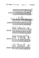
- FIG. 1 A section through a composite material in accordance with the invention.
- FIGS. 2-5 Sectional views as in FIG. 1 showing the basic stages of production of a graphic pattern on a composite material as in FIG. 1.
- FIG. 6 A sectional front view, schematically drawn, of a device for providing a strip shaped foil of aluminum, which may be stuck on to a plastic support foil, with an aluminum oxide layer.
- FIG. 7 The same kind of schematic drawing as in FIG. 6, this time showing another version of the device.
- the composite material of FIG. 1 has four layers.
- the bottom layer is a supporting layer 1 of flexible plastic which is stable with respect to light rays, etch-proof and heat-proof.
- the stability with respect to light rays is achieved by the plastic having a known additive which absorbs UV light rays, mixed into it before being manufactured as a foil for the supporting layer 1.
- the plastic can be a polyester.
- the thickness of the support film can be 100 to 200 ⁇ m, by way of example 180 ⁇ m.
- An aluminum foil 2 is stuck on to the support film 1 by means of an adhesive which is not shown here.
- the thickness of the aluminum foil is preferably 5 to 100 ⁇ m, by way of example 40 ⁇ m.
- an aluminum oxide layer 3 which is at least 3 ⁇ m thick. In one example the aluminum oxide layer is 8 ⁇ m.
- the aluminum oxide layer 3 On top of the aluminum oxide layer 3 there is a layer 4 of light-sensitive plastic, a so-called PR layer (Photo Resist layer).
- PR layer Photo Resist layer
- the plastic of the layer has the property of hardening when exposed to UV light.
- Both the aluminum oxide layer 3 and the supporting layer 1 can be colored, if desired in contrasting colors.
- the supporting foil 1 can also be transparent.
- FIG. 2 shows the first stage of production of such a pattern.
- a master pattern e.g. a film negative 5 is laid next to the PR layer.
- the master pattern has light-transparent areas 6, and areas 7 shown as dark in the drawing and which are nontransparent.
- the master pattern is then illuminated with UV light in such a way that the UV light is traveling approximately parallel to the arrow F when it strikes the master pattern.
- the master pattern allows the UV light to pass through the transparent areas 6 where it strikes the PR layer beneath and causes the PR layer to be hardened there (negative-positive process).
- the parts of the PR layer under the nontransparent areas 7 remain unchanged. In the same way a positive-positive process could be used whereby on developing, the exposed areas are removed.
- the material of layers 2 and 3 lying immediately below the places where the PR layer was removed is etched away to expose the supporting foil 1 leaving deeper hollows 7". Even if the sides 8 of the hollows 7" are not as vertical to the supporting foil 1 as shown in FIGS. 4 and 5, on etching an accuracy of the same order of magnitude as picture points is achieved with the projections at the light areas.
- the copying of the pattern can in practice be of such a high quality that grey and intermediate tones can be reproduced.
- the PR layer on the hardened areas are removed with an organic solvent to prevent the quality of the pattern produced from degenerating as a result of fading of the remaining part of the PR layer.
- the finished article as in FIG. 5 bears a durable pattern on a flexible substrate and depending on the coloring of the aluminum oxide layer 3 and the coloring of the transparent or opaque supporting layer 1, offers graphic images of the most varied kind which can find applications of the widest possible variety.
- the composite material in accordance with FIG. 1 is particularly suitable for fast and inexpensive production of nameplates, instruction panels, etc.
- the plate bearing a pattern, e.g. an inscription, produced as shown in FIGS. 2-5, can be mounted on a rigid supporting plate or can be affixed directly to the place of application.
- the latter method of use offers the advantage that because the composite is flexible it can be mounted around corners or edges.
- the device shown in FIG. 6 in cross section has a container for an electrolyte 22, e.g. a dilute sulphuric acid.
- the electrolyte is subdivided by exchangeable separating walls 24, 26 and 28 into chambers 30, 32, 34 and 36.
- a strip 40 of foil material is led upwards to an anode roll 42 denoted by a + sign from a supply coil not shown in FIG. 6.
- the strip may be a laminate produced by sticking a blank aluminum foil on to a plastic support foil, or may simply be the aluminum foil.
- the thickness of the support foil, if used, is at least 10 ⁇ m, e.g. 180 ⁇ m, while the aluminum is 5 to 100 ⁇ m thick, e.g. 40 ⁇ m.
- the aluminum side of the strip 40 faces the anode roll so that the anodizing current can be taken up by the strip from the roll.
- the anodizing roll 42 deflects the strip 40 through 90° so that the strip 40 passes horizontally through the electrolyte.
- the strip 40 may be cooled between the entry slit and the anode roll 42 by a ventilator fan (not shown here), which blows a stream of air on to the aluminum side of the foil in the direction of the arrow 46.
- the air cooling has been found to be surprisingly useful. With it a deformation due to excessive heating can be avoided. This excessive heating arises because a large electrical current has to be passed through a very small cross section. Because the cross section of the aluminum is very small the electrical resistance is very high and leads to the heating effect just mentioned.
- the amount of cooling can be kept small by making the distance between the anode roll 42 and the inlet slit 44 to the bath as short as possible. Such a construction is preferred therefore. There is however a lower limit to the diameter which the anode roll 42 can have. Thus a construction, in which a special deflection roll of small diameter is used, is preferred. This deflection roll is advantageously watercooled. The larger diameter, separate anode roll is placed as close as possible to the electrolyte. Such a construction is shown in FIG. 7 which is still to be described.
- a projecting wall 48 is provided to prevent any mechanical damage to the strip 40 between the anode roll 42 and the entry slit 44, the said projecting wall 48 preventing the strip 40 from buckling under the pressure of the cold air stream.
- Cathodes 50, 52, 54 and 56 are provided in the tank sections 30 to 36.
- the cathodes can desirably be tilted at various angles.
- the oxide layer can be regarded as an ohmic resistance.
- the voltage loss increases therefore along the whole length of the bath so that there is tendency for the greater part of the current to flow in the unoxidized or little oxidized part of the strip. This would lead to damaging or scorching of the foil.
- This harmful tendency is opposed first of all by dividing the bath into sections 30 to 35, by the distribution and arrangement of the cathode, and by the separate power supply.
- the cathodes 50 to 56 are supplied from a common transformer 60 via individual rectifiers 62, 64, 66 and 68 which are adjusted for each cathode.
- the leads from the rectifiers 62 to 68 are so connected to the transformer windings that the cathode next to the entry slit 44 has the lowest voltage. This voltage is then increased with increasing distance of the cathode in question from the entry point 44 and the increase may for example be linear.
- the cathodes are placed closer to the strip the further the cathode is from the entry point 44.
- the strip is fed into the bath through the entry slit 44 and led out through the exit slit 70. Any electrolyte which spills out through these slits is collected in the overflow tanks 45 and 72 and if desired returned to the tank 22.
- the foil which has now been provided with an aluminum oxide layer is deflected over a roll 74 and led to a coiling roll which is not shown.
- This coiling roll and/or the roll 74 can be power driven and function as the drive roll to pull the strip from the uncoiling roll which is not shown through the bath.
- a strip speed can be 1-2 m/min. with the device shown.
- a 50 cm wide strip of which 13.5 m is immersed in the electrolyte at any given time and using a current density of 139 A/mm 2 can be provided continuously with an aluminum oxide layer 8 ⁇ m thick with a throughput of 480 m 2 /8 h.
- the device as in FIG. 7 has a container 80 which is divided into sections 90, 92, 94, 96 and 98 by the dividing walls 82, 84, 86 and 88.
- the strip 40 is led over a small water-cooled deflection roll 100.
- an anode roll 102 which contacts the strip on its aluminum side if a composite is used at about the height of the deflection roll.
- the strip is deflected into a horizontal plane in the first section by means of a further deflection roll 106 and led through the dividing walls, through the individual sections of the bath to another deflection roll 108 in the last section 98 where the strip is led vertically upwards again and out to a power driven roll which pulls the strip through the tank.
- a cathode 112, 114 and 116 is arranged in each of the sections 92 to 96 all at the same distance from the strip and facing its aluminum side.
- the cathode 112 is separated from the entry point 103 by a dividing wall 82.
- This dividing wall is provided however with the device in accordance with FIG. 7 to avoid a short circuit between the entry point 103 of the strip and the cathode 112. A short circuit could otherwise occur because the resistance to the passage of the electric current is smaller there than through the bath and the strip which has an increasingly thicker oxide layer the further from the entry point 103 and therefore has a larger electrical resistance.
- the power supply to the cathodes 112, 114 and 116 is not shown in FIG. 7. It can take place in the same way as in the device shown in FIG. 6 where the transformer winding 60 is connected to the anode supply via a supply line 61 which ends in an arrow in FIG. 6.
- the described anodic oxidation of the foil takes place only after some preparatory treatment of the foil.
- the foil is firstly degreased and then with intermediate rinsing, is etched, neutralized and dried. These treatments can for the greater part take place by immersion and/or spraying and usefully are done continuously and at the same rate as the anodic oxidation.
- the strip can be treated with a nitric acid solution, rinsed again and then colored in a continuous process whereby the quality of the color is dependent on the thickness of the aluminum oxide layer produced by the anodic oxidation.
- the minimum thickness of oxide layer is about 3 ⁇ m.
- the coloring takes place conventionally by immersing in a bath whereby the indigenous pores in the aluminum oxide layer are filled with coloring material.
- the strip is rinsed once more and then subjected to a sealing operation.
- the pores filled with coloring material are closed by making the oxide layer swell in almost boiling water.
- care must be taken that the support foil does not become wavy on immersing in hot water or steam. For this reason the sealing temperature is lower than in the normal sealing operation and in one device used was 80° C.
- the result is a foil material with a colored and sealed aluminum oxide.
- the aluminum oxide layer may be coated with a PR layer as processed as aforesaid.
Landscapes
- Chemical & Material Sciences (AREA)
- Engineering & Computer Science (AREA)
- Chemical Kinetics & Catalysis (AREA)
- Electrochemistry (AREA)
- Materials Engineering (AREA)
- Metallurgy (AREA)
- Organic Chemistry (AREA)
- Physics & Mathematics (AREA)
- General Physics & Mathematics (AREA)
- Laminated Bodies (AREA)
- Printing Methods (AREA)
- Printing Plates And Materials Therefor (AREA)
Applications Claiming Priority (2)
| Application Number | Priority Date | Filing Date | Title |
|---|---|---|---|
| DE2340962 | 1973-08-13 | ||
| DE19732340962 DE2340962A1 (de) | 1973-08-13 | 1973-08-13 | Verbundwerkstoff und verfahren sowie vorrichtung zu seiner herstellung |
Related Parent Applications (2)
| Application Number | Title | Priority Date | Filing Date |
|---|---|---|---|
| US05/764,001 Division US4158079A (en) | 1973-08-13 | 1977-01-31 | Composite material and a process and device for its manufacture |
| US05/926,280 Continuation-In-Part US4177127A (en) | 1973-08-13 | 1978-07-20 | Device for the production of anodized material |
Publications (1)
| Publication Number | Publication Date |
|---|---|
| US4239610A true US4239610A (en) | 1980-12-16 |
Family
ID=5889639
Family Applications (1)
| Application Number | Title | Priority Date | Filing Date |
|---|---|---|---|
| US06/051,453 Expired - Lifetime US4239610A (en) | 1973-08-13 | 1979-06-22 | Device for the production of anodized material |
Country Status (13)
| Country | Link |
|---|---|
| US (1) | US4239610A (de) |
| JP (1) | JPS5044007A (de) |
| BE (1) | BE818655A (de) |
| CA (1) | CA1041348A (de) |
| CH (1) | CH579458A5 (de) |
| DE (1) | DE2340962A1 (de) |
| DK (1) | DK374974A (de) |
| FR (1) | FR2241097A1 (de) |
| GB (1) | GB1468447A (de) |
| IT (1) | IT1027544B (de) |
| NL (1) | NL7409559A (de) |
| NO (1) | NO742891L (de) |
| SE (1) | SE7410271L (de) |
Cited By (3)
| Publication number | Priority date | Publication date | Assignee | Title |
|---|---|---|---|---|
| US4437957A (en) | 1982-05-03 | 1984-03-20 | Freeman Industries, Inc. | Cathodic or anodic protection system and method for independently protecting different regions of a structure |
| US6649039B2 (en) * | 2001-10-24 | 2003-11-18 | Hon Hai Precision Ind. Co., Ltd. | Process of surface treating aluminum articles |
| US20130233702A1 (en) * | 2012-03-09 | 2013-09-12 | Chung-Shan Institute of Science and Technology, Armaments, Bureau, Ministry of National Defense | Multi-Stationed Continuous Electro-Polishing System |
Citations (6)
| Publication number | Priority date | Publication date | Assignee | Title |
|---|---|---|---|---|
| US2541275A (en) * | 1943-11-09 | 1951-02-13 | Alais & Froges & Camarque Cie | Apparatus for the electrolytic oxidation of metallic elements |
| US2951025A (en) * | 1957-06-13 | 1960-08-30 | Reynolds Metals Co | Apparatus for anodizing aluminum |
| US3074857A (en) * | 1957-11-23 | 1963-01-22 | Aluminium Walzwerke Singen | Method and apparatus for producing dielectric layer on the surface of an aluminum foil |
| US3510410A (en) * | 1965-07-16 | 1970-05-05 | Harry Pierre Rosenthal | Production of electrolytic condensers |
| US3864235A (en) * | 1971-08-25 | 1975-02-04 | Bobrov S B | Loop electrolyzer |
| US3970537A (en) * | 1973-07-11 | 1976-07-20 | Inland Steel Company | Electrolytic treating apparatus |
-
1973
- 1973-08-13 DE DE19732340962 patent/DE2340962A1/de active Pending
-
1974
- 1974-06-11 CH CH794474A patent/CH579458A5/xx not_active IP Right Cessation
- 1974-07-12 JP JP49080083A patent/JPS5044007A/ja active Pending
- 1974-07-12 DK DK374974A patent/DK374974A/da unknown
- 1974-07-15 NL NL7409559A patent/NL7409559A/xx unknown
- 1974-08-09 FR FR7427799A patent/FR2241097A1/fr not_active Withdrawn
- 1974-08-09 BE BE147435A patent/BE818655A/xx unknown
- 1974-08-12 SE SE7410271A patent/SE7410271L/xx unknown
- 1974-08-12 CA CA206,826A patent/CA1041348A/en not_active Expired
- 1974-08-12 NO NO742891A patent/NO742891L/no unknown
- 1974-08-13 GB GB3553074A patent/GB1468447A/en not_active Expired
- 1974-08-13 IT IT26288/74A patent/IT1027544B/it active
-
1979
- 1979-06-22 US US06/051,453 patent/US4239610A/en not_active Expired - Lifetime
Patent Citations (6)
| Publication number | Priority date | Publication date | Assignee | Title |
|---|---|---|---|---|
| US2541275A (en) * | 1943-11-09 | 1951-02-13 | Alais & Froges & Camarque Cie | Apparatus for the electrolytic oxidation of metallic elements |
| US2951025A (en) * | 1957-06-13 | 1960-08-30 | Reynolds Metals Co | Apparatus for anodizing aluminum |
| US3074857A (en) * | 1957-11-23 | 1963-01-22 | Aluminium Walzwerke Singen | Method and apparatus for producing dielectric layer on the surface of an aluminum foil |
| US3510410A (en) * | 1965-07-16 | 1970-05-05 | Harry Pierre Rosenthal | Production of electrolytic condensers |
| US3864235A (en) * | 1971-08-25 | 1975-02-04 | Bobrov S B | Loop electrolyzer |
| US3970537A (en) * | 1973-07-11 | 1976-07-20 | Inland Steel Company | Electrolytic treating apparatus |
Cited By (3)
| Publication number | Priority date | Publication date | Assignee | Title |
|---|---|---|---|---|
| US4437957A (en) | 1982-05-03 | 1984-03-20 | Freeman Industries, Inc. | Cathodic or anodic protection system and method for independently protecting different regions of a structure |
| US6649039B2 (en) * | 2001-10-24 | 2003-11-18 | Hon Hai Precision Ind. Co., Ltd. | Process of surface treating aluminum articles |
| US20130233702A1 (en) * | 2012-03-09 | 2013-09-12 | Chung-Shan Institute of Science and Technology, Armaments, Bureau, Ministry of National Defense | Multi-Stationed Continuous Electro-Polishing System |
Also Published As
| Publication number | Publication date |
|---|---|
| DK374974A (de) | 1975-04-07 |
| DE2340962A1 (de) | 1975-02-27 |
| BE818655A (fr) | 1974-12-02 |
| NL7409559A (nl) | 1975-02-17 |
| SE7410271L (de) | 1975-02-14 |
| FR2241097A1 (de) | 1975-03-14 |
| GB1468447A (en) | 1977-03-23 |
| JPS5044007A (de) | 1975-04-21 |
| IT1027544B (it) | 1978-12-20 |
| NO742891L (de) | 1975-03-10 |
| CH579458A5 (de) | 1976-09-15 |
| CA1041348A (en) | 1978-10-31 |
Similar Documents
| Publication | Publication Date | Title |
|---|---|---|
| US4158079A (en) | Composite material and a process and device for its manufacture | |
| US2854336A (en) | Method of forming a two-level photoengraved embossing plate or mold | |
| FI80350B (fi) | Ljuskaensliga polymerkompositioner, elektroforetiska skiktbildningsfoerfaranden daer dessa anvaendes och deras anvaendning vid bildning av filmer pao underlag. | |
| US4193848A (en) | Process for the production of composite material | |
| US20110089042A1 (en) | method of manufacturing a gas electron multiplier | |
| WO2018066844A1 (ko) | 증착용 마스크로 사용되는 합금 금속박, 증착용 마스크 및 이들의 제조방법과 이를 이용한 유기 발광 소자 제조방법 | |
| US4239610A (en) | Device for the production of anodized material | |
| DE2514176A1 (de) | Gekruemmte starre schaltungsplatte und verfahren zum herstellen derselben | |
| US4177127A (en) | Device for the production of anodized material | |
| US3989605A (en) | Method for continuous electrolytic coloring of aluminum articles | |
| CN110126438B (zh) | 一种非平整面印刷网版的制作方法 | |
| US2900580A (en) | Printed electrical circuit components having integral lead-outs and methods of making same | |
| DE1521306B2 (de) | Verfahren zum elektrolytischen oder chemischen aufbringen von elektrischen leitungszuegen | |
| KR101299556B1 (ko) | 스크린 인쇄를 위한 금속제판 제조방법 | |
| JPH07243086A (ja) | 装飾板及びその製造方法 | |
| US3197391A (en) | Method of etching aluminum | |
| US5164033A (en) | Electro-chemical etch device | |
| ATE926T1 (de) | Verfahren zur behandlung von aluminiumfolien oder flachdruckplatten sowie die so erhaltenen produkte. | |
| DE2254503C2 (de) | Für die Herstellung von Bimetallplatten für den Flachdruck geeignetes flächiges Material | |
| JPS5844760B2 (ja) | 穿孔された金属ホイルの製造法 | |
| DE2340961A1 (de) | Vorrichtung zum herstellen von graphischen mustern | |
| CN218004292U (zh) | 一种铝标牌的环保制作设备 | |
| DE2340963A1 (de) | Verfahren und vorrichtung zum oxidieren einer folie aus aluminium oder einer seiner legierungen | |
| CN1126148A (zh) | 具有彩色图形面的压花不锈钢星光板及其制作方法 | |
| JPH0158279B2 (de) |