US4215971A - Lift truck - Google Patents
Lift truck Download PDFInfo
- Publication number
- US4215971A US4215971A US05/915,889 US91588978A US4215971A US 4215971 A US4215971 A US 4215971A US 91588978 A US91588978 A US 91588978A US 4215971 A US4215971 A US 4215971A
- Authority
- US
- United States
- Prior art keywords
- mast
- frame
- pivot pin
- truck
- slide block
- Prior art date
- Legal status (The legal status is an assumption and is not a legal conclusion. Google has not performed a legal analysis and makes no representation as to the accuracy of the status listed.)
- Expired - Lifetime
Links
Images


Classifications
-
- B—PERFORMING OPERATIONS; TRANSPORTING
- B66—HOISTING; LIFTING; HAULING
- B66F—HOISTING, LIFTING, HAULING OR PUSHING, NOT OTHERWISE PROVIDED FOR, e.g. DEVICES WHICH APPLY A LIFTING OR PUSHING FORCE DIRECTLY TO THE SURFACE OF A LOAD
- B66F9/00—Devices for lifting or lowering bulky or heavy goods for loading or unloading purposes
- B66F9/06—Devices for lifting or lowering bulky or heavy goods for loading or unloading purposes movable, with their loads, on wheels or the like, e.g. fork-lift trucks
- B66F9/065—Devices for lifting or lowering bulky or heavy goods for loading or unloading purposes movable, with their loads, on wheels or the like, e.g. fork-lift trucks non-masted
-
- Y—GENERAL TAGGING OF NEW TECHNOLOGICAL DEVELOPMENTS; GENERAL TAGGING OF CROSS-SECTIONAL TECHNOLOGIES SPANNING OVER SEVERAL SECTIONS OF THE IPC; TECHNICAL SUBJECTS COVERED BY FORMER USPC CROSS-REFERENCE ART COLLECTIONS [XRACs] AND DIGESTS
- Y10—TECHNICAL SUBJECTS COVERED BY FORMER USPC
- Y10S—TECHNICAL SUBJECTS COVERED BY FORMER USPC CROSS-REFERENCE ART COLLECTIONS [XRACs] AND DIGESTS
- Y10S414/00—Material or article handling
- Y10S414/13—Handlers utilizing parallel links
Definitions
- This invention relates in general to material handling equipments and has specific reference to an improved lift truck of the type comprising a load-carrying platform movable vertically under the control of a hoisting device comprising a mast mounted at the front end of the truck and supporting said platfrom.
- This invention is concerned more particularly with a lift truck capable of meeting the requirements of safety regulations in force and of which the hoisting device cannot interfere with the stability, dimensional limits or mass of the truck.
- Hitherto known lift trucks comprise as a rule a mast, whether fixed or hingedly mounted, disposed ahead of the front drive-wheel axle, this mast constituting the means for guiding a load-carrying platform adapted to receive tools such as forks, clamps or other specialized tools. Under the control of a hydraulic cylinder, the load can travel parallel to the mast.
- This conventional structure leads to the construction of lift trucks supporting the load ahead of the front-drive axle, so that the steering rear axle must be ballasted in order to transfer the centre of gravity of the truck inside its polygonal basis of support.
- this polygonal basis is an isosceles triangle of which the vertices constitute the projection on the ground of the vertical pivot axis of the steering axle and the points of contact between the drive wheels and the ground. Therefore, known trucks are relatively bulky and heavy, so that their operation is attended by a considerable power consumption. Furthermore, the position of the centre of gravity above the ground increases the risks of tipping the truck, for example when changing its direction of travel or applying the brakes. It is also clear that the increment in the truck mass, its distribution and the position of its centre of gravity develop vertical, transverse and longitudinal inertia forces, and consequently stray movements tending to endanger the operator's safety and the truck load.
- the base of the hoisting mast carries a pivot pin rigid with a slide block mounted for longitudinal translation on the lower portion of the truck frame under the control of fluid-operated means.
- the hoisting mast can be moved to any desired inclined position, including a substantially horizontal position in which its centre of gravity lies between the two truck axles, thus improving considerably the static stability and the operator's field of vision.
- the centre of gravity of the truck is located at a very low level above the ground, the truck becomes insensitive to dynamic effects resulting from its acceleration and decelerations.
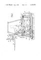
- FIG. 1 is a diagrammatical side elevational view of the truck frame showing the hoisting mast and the load supporting platform in its uppermost position;
- FIG. 2 is a view similar to FIG. 1 but showing the mast and platform control means in their lowermost position
- FIG. 3 is a plane view from above showing the truck with the load supporting platform in its lowermost position.
- the truck illustrated in FIGS. 1 and 2 comprises a frame 1, a pair of drive wheels 2 and a pair of steering or driving-cum-steering wheels 3, mounted on front and rear axles, respectively, of the truck.
- the frame 1 comprises essentially at its lower portion a pair of longitudinal side members 5, 6 supporting a connecting plate 7 and braced by three cross members 8, 9 and 10.
- Each longitudinal side member extends between the front and rear wheels 2, 3 and consists of an I-section member with horizontal wings directed towards the longitudinal centre line of the truck.
- the wings of the two section members 5, 6 constitute guide races for rollers, as will be explained presently.
- a pair of vertical H-sectioned stanchions or like members 11 and 12 are each rigid with one of said longitudinal members 5 and 6, respectively.
- the front stanchions 11 support the axle of the drive wheels, and the rear stanchions 12 have anchored thereto two hydraulic cylinders to be described presently.
- a number of ribs (not shown) are provided in order to impart to the frame the rigidity and strength necessary for absorbing the torque reaction of the truck and the reaction force of the control cylinder.
- the storage batteries 13 for energizing the drive motor 14, the oil tank 15, the counterweight 16, one portion of the reinforced protection cab for the operator, as well as the steering mechanism 17, are shown only diagrammatically, since they are well known in the art.
- the hoisting means illustrated more in detail in FIG. 1 comprise essentially at least one hoisting mast 19 consisting, for example, of a beam capable of withstanding severe torsional and flexion stresses.
- the front end of the mast 19 carries a load-supporting platform or like tool, in this example a conventional fork 20 for palletizing loads, of the variable-track type, supported by a pair of cross members 21, 22 interconnected by gussets 23 and extending transversely to the longitudinal centre line of the truck.
- the length of these cross members 21, 22 is substantially inferior to the overall width of the truck.
- the distance between the fork arms is adjusted in the conventional manner by causing said arms to slide on the cross members 21, 22.
- the load supporting platform is anchored to the mast 19 by means of a pin 24 carried by brackets 23a.
- the hoisting mast is associated with means capable of assuming a horizontal position when the load platform is moved to its lowermost or bottom position.
- the base of mast 19 carries a pivot pin 25 rigid with a slide block 26.
- the latter consists of a small guided carriage comprising essentially a pair of small longitudinal side members braced to each other and carrying four rollers 26a engaging the inner race-forming surfaces of the wings of the I-sectioned longitudinal members 5, 6 so as to be guided thereby.
- the rollers 26a allow the movements of translation of slide block 26 and consequently the movements of the pivot pin 25 in a horizontal plane.
- the slide block or guided carriage 26 is also provided with another transverse pivot pin 30 to which one end of a main positioning rod 28 is pivoted, the other end of this rod 28 being pivoted to another pivot pin 27 secured to a pair of brackets 29 rigid with the upper cross member 22.
- pivot pins 25 and 30 carried by the carriage 26 are equal to the distance between the axes of the pivot pins 24 and 27.
- These pivot pins 25, 30 and 24, 27 are on the other hand parallel to each other and lie in parallel planes, so that they constitute the vertices of a rigid parallelipipedic structure during the movements of carriage 26.
- the frame 1 carries the fixed pivot pin 31 of a support rod 32 having a length equal to one-half the distance between the pivot pin 25 of the hoisting mast 19 on the guide carriage 26, on the one hand, and the pivot pin 24 of the fork assembly 20-23, on the other hand.
- the pivot pin 31 is coaxial to the pivot pin 24 when the platform is in its lowermost position.
- the supporting rod 32 is pivoted on the other hand to the mast 19 about a pivot pin 0' located intermediate the parallel pivot pins 25, 24 and in the plane containing the axes of these pivot pins.
- the above-described structure is capable of lifting loads in a vertical plane under the control of power means to be described hereinafter with reference to the drawing.
- the hoisting mast 19 carries means for anchoring a traction member coupled to a cylinder.
- These anchoring means consist of a bracket 37 welded to the mast.
- the bracket 37 carries the pivot pin 36 of a pivoted lug 38.
- This lug 38 is rigidly connected to the traction member consisting in this example of a chain 39 co-operating with the contact surface of a cam 40 rotatably mounted on a shaft 45.
- a pair of hydraulic cylinders 41 control the upward and downward movements of the mast.
- each cylinder 41 is pivoted to a stanchion 12 and the piston rod 42 of the corresponding cylinder carries a tension roller 43 for the traction chain 39, this chain having its ends anchored the one to the lug 38 and the other to the cylinder 41, respectively.
- the traction or tension stress exerted on the chain 39 is supported by the shaft 45 of cam 40.
- the shaft 45 is carried by a bracket welded to an element of the truck frame 1. The contour of this cam 40 is such that the control effort transmitted to the mast 19 via chain 39 is directed substantially at right angles to said mast 19.
- the portion of chain 39 between the tension roller 43 and lug 38 is wound during one fraction of the movement of mast 19 over the cam 40 while preserving the coupling with play between the lug 38 and a notch 46 formed in said cam 40.
- the lug 38 is disengaged from notch 46 and the engagement between the lug 38 and cam notch 46 is restored during the downward movement of the mast.
- the piston rods 42 pull the chain 39 and consequently the lug 38.
- the profile of cam 40 is such that the efforts exerted on the cylinders 41 and mast 19 are somewhat limited.
- the flexion stress exerted on the cylinder body may be reduced considerably and the velocity of operation of the mast 19 shall be calculated as a function of a law of variation of the cylinder control pressure.
- the vertical movements accomplished by the load-supporting platform and the corresponding movements of the piston rods 42 of said cylinders are governed by a law of variation taking due account of the cam profile and of the positions of anchoring points 37.
- Two vertical parallel plates G bolted to the corresponding side members 5 and 6 and on the vertical stanchions 11 at the front of the truck are provided for guiding the mast 19 during its ascent or descent, to prevent accidental lateral shifts of the mast and the load supported thereby.
- the positioning rod 28 may comprise, if desired, an additional protection frame extending vertically in front of the operator's knees during the truck travel with the mast 19 in its retracted or lowermost position.
- an additional protection frame extending vertically in front of the operator's knees during the truck travel with the mast 19 in its retracted or lowermost position.
- control means comprising a fluid-operated cylinder adapted to actuate simultaneously with its traction member a pair of hoisting masts disposed on either side of the cylinder may be incorporated in the truck of this invention, without departing from its basic principles.
Landscapes
- Engineering & Computer Science (AREA)
- Transportation (AREA)
- Structural Engineering (AREA)
- Civil Engineering (AREA)
- Life Sciences & Earth Sciences (AREA)
- Geology (AREA)
- Mechanical Engineering (AREA)
- Forklifts And Lifting Vehicles (AREA)
Abstract
The lift truck of the invention comprises a frame, a mast adapted to be lifted in relation to the frame, a fluid-operated cylinder for controlling the ascent and descent of the mast, a load-supporting platform rigid with the mast, a first pivot pin carried by the lower end of the mast and rigid with a movable slide block guided horizontally along the lower portion of the frame. The slide block carries the pivot pin of a positioning rod for positioning the load supporting platform and a supporting rod, having a length equal to one-half of the distance between the pivot pin of the mast on the slide block and the pivot pin of the load supporting platform on the mast, is pivoted to the mast and to the lower portion of the frame ahead of the slide block.
Description
This invention relates in general to material handling equipments and has specific reference to an improved lift truck of the type comprising a load-carrying platform movable vertically under the control of a hoisting device comprising a mast mounted at the front end of the truck and supporting said platfrom.
This invention is concerned more particularly with a lift truck capable of meeting the requirements of safety regulations in force and of which the hoisting device cannot interfere with the stability, dimensional limits or mass of the truck.
It is known that a good truck stability is essential for improving its safety of operation and its performances in actual service, such as speed, acceleration and braking, while reducing to a large extent the load ascent and descent times.
Hitherto known lift trucks comprise as a rule a mast, whether fixed or hingedly mounted, disposed ahead of the front drive-wheel axle, this mast constituting the means for guiding a load-carrying platform adapted to receive tools such as forks, clamps or other specialized tools. Under the control of a hydraulic cylinder, the load can travel parallel to the mast.
This conventional structure leads to the construction of lift trucks supporting the load ahead of the front-drive axle, so that the steering rear axle must be ballasted in order to transfer the centre of gravity of the truck inside its polygonal basis of support. As a rule, this polygonal basis is an isosceles triangle of which the vertices constitute the projection on the ground of the vertical pivot axis of the steering axle and the points of contact between the drive wheels and the ground. Therefore, known trucks are relatively bulky and heavy, so that their operation is attended by a considerable power consumption. Furthermore, the position of the centre of gravity above the ground increases the risks of tipping the truck, for example when changing its direction of travel or applying the brakes. It is also clear that the increment in the truck mass, its distribution and the position of its centre of gravity develop vertical, transverse and longitudinal inertia forces, and consequently stray movements tending to endanger the operator's safety and the truck load.
It is therefore the essential object of the present invention to provide a lift truck having an improved stability and wherein the assembly of means implemented for obtaining this improved stability do not modify in any way the overall dimensions and mass of the truck.
It is another object of this invention to provide a lift truck in which the hoisting means are so arranged that the operator's visibility is greatly improved.
It is a further object of this invention to provide a lift truck wherein the component elements of the hoisting device are positioned with a view to reduce appreciably the masses located ahead of the drive or front axle, lower the centre of gravity and increase the visual field of the operator.
According to this invention, the base of the hoisting mast carries a pivot pin rigid with a slide block mounted for longitudinal translation on the lower portion of the truck frame under the control of fluid-operated means.
In the lift truck thus constructed the hoisting mast can be moved to any desired inclined position, including a substantially horizontal position in which its centre of gravity lies between the two truck axles, thus improving considerably the static stability and the operator's field of vision.
Moreover, since the centre of gravity of the truck is located at a very low level above the ground, the truck becomes insensitive to dynamic effects resulting from its acceleration and decelerations.
Other features and advantages of the improved lift truck of this invention will appear as the following description of a typical form of embodiment thereof proceeds, reference being made by way of example to the attached drawing, in which:
FIG. 1 is a diagrammatical side elevational view of the truck frame showing the hoisting mast and the load supporting platform in its uppermost position;
FIG. 2 is a view similar to FIG. 1 but showing the mast and platform control means in their lowermost position, and
FIG. 3 is a plane view from above showing the truck with the load supporting platform in its lowermost position.
The truck illustrated in FIGS. 1 and 2 comprises a frame 1, a pair of drive wheels 2 and a pair of steering or driving-cum-steering wheels 3, mounted on front and rear axles, respectively, of the truck.
The frame 1 comprises essentially at its lower portion a pair of longitudinal side members 5, 6 supporting a connecting plate 7 and braced by three cross members 8, 9 and 10. Each longitudinal side member extends between the front and rear wheels 2, 3 and consists of an I-section member with horizontal wings directed towards the longitudinal centre line of the truck. The wings of the two section members 5, 6 constitute guide races for rollers, as will be explained presently.
A pair of vertical H-sectioned stanchions or like members 11 and 12 are each rigid with one of said longitudinal members 5 and 6, respectively. The front stanchions 11 support the axle of the drive wheels, and the rear stanchions 12 have anchored thereto two hydraulic cylinders to be described presently.
A number of ribs (not shown) are provided in order to impart to the frame the rigidity and strength necessary for absorbing the torque reaction of the truck and the reaction force of the control cylinder.
In the drawing, the storage batteries 13 for energizing the drive motor 14, the oil tank 15, the counterweight 16, one portion of the reinforced protection cab for the operator, as well as the steering mechanism 17, are shown only diagrammatically, since they are well known in the art.
The hoisting means illustrated more in detail in FIG. 1 comprise essentially at least one hoisting mast 19 consisting, for example, of a beam capable of withstanding severe torsional and flexion stresses. The front end of the mast 19 carries a load-supporting platform or like tool, in this example a conventional fork 20 for palletizing loads, of the variable-track type, supported by a pair of cross members 21, 22 interconnected by gussets 23 and extending transversely to the longitudinal centre line of the truck. The length of these cross members 21, 22 is substantially inferior to the overall width of the truck. The distance between the fork arms is adjusted in the conventional manner by causing said arms to slide on the cross members 21, 22. The load supporting platform is anchored to the mast 19 by means of a pin 24 carried by brackets 23a.
In order to meet the primary requirements of this invention, the hoisting mast is associated with means capable of assuming a horizontal position when the load platform is moved to its lowermost or bottom position.
According to the invention, the base of mast 19 carries a pivot pin 25 rigid with a slide block 26. The latter consists of a small guided carriage comprising essentially a pair of small longitudinal side members braced to each other and carrying four rollers 26a engaging the inner race-forming surfaces of the wings of the I-sectioned longitudinal members 5, 6 so as to be guided thereby. With this arrangement, the rollers 26a allow the movements of translation of slide block 26 and consequently the movements of the pivot pin 25 in a horizontal plane. The slide block or guided carriage 26 is also provided with another transverse pivot pin 30 to which one end of a main positioning rod 28 is pivoted, the other end of this rod 28 being pivoted to another pivot pin 27 secured to a pair of brackets 29 rigid with the upper cross member 22. By construction, the distance between the pivot pins 25 and 30 carried by the carriage 26 is equal to the distance between the axes of the pivot pins 24 and 27. These pivot pins 25, 30 and 24, 27 are on the other hand parallel to each other and lie in parallel planes, so that they constitute the vertices of a rigid parallelipipedic structure during the movements of carriage 26.
To obtain a vertical movement of the pivot pins 24, 27 during the forward movement of the slide block or carriage 26, the frame 1 carries the fixed pivot pin 31 of a support rod 32 having a length equal to one-half the distance between the pivot pin 25 of the hoisting mast 19 on the guide carriage 26, on the one hand, and the pivot pin 24 of the fork assembly 20-23, on the other hand. The pivot pin 31 is coaxial to the pivot pin 24 when the platform is in its lowermost position. The supporting rod 32 is pivoted on the other hand to the mast 19 about a pivot pin 0' located intermediate the parallel pivot pins 25, 24 and in the plane containing the axes of these pivot pins.
The above-described structure is capable of lifting loads in a vertical plane under the control of power means to be described hereinafter with reference to the drawing.
The hoisting mast 19 carries means for anchoring a traction member coupled to a cylinder. These anchoring means consist of a bracket 37 welded to the mast. The bracket 37 carries the pivot pin 36 of a pivoted lug 38. This lug 38 is rigidly connected to the traction member consisting in this example of a chain 39 co-operating with the contact surface of a cam 40 rotatably mounted on a shaft 45. A pair of hydraulic cylinders 41 control the upward and downward movements of the mast. To this end, the body of each cylinder 41 is pivoted to a stanchion 12 and the piston rod 42 of the corresponding cylinder carries a tension roller 43 for the traction chain 39, this chain having its ends anchored the one to the lug 38 and the other to the cylinder 41, respectively. The traction or tension stress exerted on the chain 39 is supported by the shaft 45 of cam 40. To this end, the shaft 45 is carried by a bracket welded to an element of the truck frame 1. The contour of this cam 40 is such that the control effort transmitted to the mast 19 via chain 39 is directed substantially at right angles to said mast 19. For this purpose, the portion of chain 39 between the tension roller 43 and lug 38 is wound during one fraction of the movement of mast 19 over the cam 40 while preserving the coupling with play between the lug 38 and a notch 46 formed in said cam 40. At the end of the mast stroke, the lug 38 is disengaged from notch 46 and the engagement between the lug 38 and cam notch 46 is restored during the downward movement of the mast.
The above-described structure operates as follows:
When the cylinder or cylinders 41 are actuated by introducing fluid under pressure into them, the piston rods 42 pull the chain 39 and consequently the lug 38. The profile of cam 40 is such that the efforts exerted on the cylinders 41 and mast 19 are somewhat limited. According to a preferred form of embodiment of the present invention, the flexion stress exerted on the cylinder body may be reduced considerably and the velocity of operation of the mast 19 shall be calculated as a function of a law of variation of the cylinder control pressure. The vertical movements accomplished by the load-supporting platform and the corresponding movements of the piston rods 42 of said cylinders are governed by a law of variation taking due account of the cam profile and of the positions of anchoring points 37. More particularly, it will be possible to actuate the mast 19 by using a relatively moderate amount of power, and to store one fraction of this power during the downward movement of the mast either in the form of hydropneumatic energy stored in a reservoir connected to the cylinders 41, or by compressing spring means housed in the cylinder bodies.
Due to the tractive effort exerted through the chain 39, the slide-block or carriage 26 is moved along the longitudinal side members 5 and 6. This movement is attended by a pivotal movement of the supporting rod 32 about the fixed pivot pin 31. The pivot axis 0' of rod 32 on mast 19 will thus describe a circular arc about the axis of pivot pin 31 and the platform provided with the fork arms 20 is moved vertically upwards, parallel to the vertical containing said axis of pivot pin 31.
Two vertical parallel plates G bolted to the corresponding side members 5 and 6 and on the vertical stanchions 11 at the front of the truck are provided for guiding the mast 19 during its ascent or descent, to prevent accidental lateral shifts of the mast and the load supported thereby.
The positioning rod 28 may comprise, if desired, an additional protection frame extending vertically in front of the operator's knees during the truck travel with the mast 19 in its retracted or lowermost position. When the load supporting platform is in the uppermost position shown in FIG. 1, the additional frame is located automatically above the operator's head to protect it against the possible fall of a load.
It would not constitute a departure from the scope of the invention to use double-acting control cylinders incorporated in the positioning rod 28, such as the cylinders 50 schematically illustrated in FIG. 1. In this case, the function of such cylinders would be to move the pivot pin towards or away from the pivot pin 30. This movement would permit, for a given position of the mast 19, a slight rotation of forks 20 about the horizontal pivot 24, notably for facilitating the picking up of a load.
It would also be possible to bring many modifications and changes to the load supporting mast and its control cylinder or cylinders without departing from the basic principles of the invention. In fact, control means comprising a fluid-operated cylinder adapted to actuate simultaneously with its traction member a pair of hoisting masts disposed on either side of the cylinder may be incorporated in the truck of this invention, without departing from its basic principles.
Claims (7)
1. In a lift truck of the type comprising a frame, a mast adapted to be pivoted in relation to said frame, a fluid-operated cylinder for controlling the ascent and descent of said mast, a load-supporting platform operatively connected with said mast, a movable slide block, a first pivot pin carried by a lower end of the mast and operatively connected with the movable slide block, the slide block being guided horizontally along the lower portion of the frame for controlling mast movements, the improvements comprising a positioning rod, said positioning rod having a pivot pin at a lower end thereof for pivotally connecting said rod to said slide block for positioning the rod and the load supporting platform , a second pivot pin carried by an upper end of the mast and connected to the load supporting platform, and a supporting rod having a length equal to one-half of the distance between the first pivot pin of said mast on the slide block and the second pivot pin, said supporting rod being pivoted to said mast and to a lower portion of said frame ahead of said slide block, the frame including a pair of longitudinal side members for defining a guide race for the slide block controlling the mast movements.
2. A lift truck as set forth in claim 1, further comprising a traction member, means for anchoring the traction member carried by said mast, a reaction member cooperating with the anchoring means and fastened to the truck frame, and mast control means including said cylinder for moving said traction member.
3. A lift truck as set forth in claim 2, wherein the cylinder of the mast control means has a body having anchored thereto one end of said traction member, the traction member cooperating with a tension member controlled by said cylinder, an absorption member for absorbing reaction of the mast to a control effort, said absorption member being rigid with the truck frame.
4. A lift truck as set forth in claim 3, wherein the absorption member consists of a cam rotatably mounted by means of a pivot pin rigid with the truck frame, and that said cam has formed therein a notch adapted to be engaged with play by a lug carried by said traction member, said lug comprising a mast control member of said mast control means.
5. A lift truck as set forth in claim 4, wherein effort transmitted through said traction member is directed substantially at right angles to the mast.
6. A lift truck as set forth in claim 1, wherein said mast is disposed between two lateral guide members consisting of a pair of parallel vertical plates rigid with said longitudinal side members of the truck, and of front stanchions of the truck frame.
7. A lift truck as set forth in claim 1, wherein the rod for positioning the load supporting platform includes means for adjusting the length of said rod, said adjusting means partaking in rotation of said load supporting platform about its pivot axis, the pivot axis consisting of a pivot pin carried by the mast.
Applications Claiming Priority (2)
| Application Number | Priority Date | Filing Date | Title |
|---|---|---|---|
| FR7719913A FR2395939A1 (en) | 1977-06-29 | 1977-06-29 | PERFECTED FORKLIFT |
| FR7719913 | 1977-06-29 |
Publications (1)
| Publication Number | Publication Date |
|---|---|
| US4215971A true US4215971A (en) | 1980-08-05 |
Family
ID=9192712
Family Applications (1)
| Application Number | Title | Priority Date | Filing Date |
|---|---|---|---|
| US05/915,889 Expired - Lifetime US4215971A (en) | 1977-06-29 | 1978-06-15 | Lift truck |
Country Status (12)
| Country | Link |
|---|---|
| US (1) | US4215971A (en) |
| EP (1) | EP0000295B1 (en) |
| JP (1) | JPS5413181U (en) |
| AU (1) | AU519105B2 (en) |
| DE (1) | DE2860801D1 (en) |
| DK (1) | DK290478A (en) |
| ES (1) | ES470725A1 (en) |
| FR (1) | FR2395939A1 (en) |
| HU (1) | HU179291B (en) |
| IT (1) | IT1109731B (en) |
| TR (1) | TR20655A (en) |
| ZA (1) | ZA783288B (en) |
Cited By (8)
| Publication number | Priority date | Publication date | Assignee | Title |
|---|---|---|---|---|
| US4699560A (en) * | 1984-12-07 | 1987-10-13 | Veb Schwermaschinenbaukombinat Takraf | Lifting apparatus suitable for equipment such as forklifts |
| US4822237A (en) * | 1985-11-21 | 1989-04-18 | The Gradall Company | Extended reach materials handling apparatus |
| US5375963A (en) * | 1993-01-19 | 1994-12-27 | Wohlwend; Clayton E. | Multipurpose lifting apparatus |
| US5709523A (en) * | 1995-06-07 | 1998-01-20 | Ware; Emmet P. | Material handling lift |
| US6726436B2 (en) | 2000-05-11 | 2004-04-27 | Ulg Omniquip, Inc. | Modular frame load handler with translatable boom carriage |
| US20040151567A1 (en) * | 2003-01-30 | 2004-08-05 | Manitou Costruzioni Industriali S.R.L. | Terminal hinge for lift trucks having telescopic arms |
| CN110482447A (en) * | 2019-08-20 | 2019-11-22 | 戚春凤 | A kind of side fork mechanism suitable for fork truck |
| US11608255B2 (en) * | 2018-07-24 | 2023-03-21 | Cargotec Research & Development Ireland Limited | Truck mounted forklift |
Families Citing this family (4)
| Publication number | Priority date | Publication date | Assignee | Title |
|---|---|---|---|---|
| JPS60237918A (en) * | 1984-05-11 | 1985-11-26 | セイレイ工業株式会社 | Structure of output part of power for driving cassette tank in combine |
| FR2690895A1 (en) * | 1992-05-07 | 1993-11-12 | Manitou Bf | Electric forklift with telescopic arm. |
| DE4320988C2 (en) * | 1993-06-24 | 1995-10-26 | Josef Paul | Transport vehicle for loading and moving containers |
| BE1012693A3 (en) * | 1999-06-01 | 2001-02-06 | Callens Ludo Genoemd Ludwig Wi | Forklift truck. |
Citations (5)
| Publication number | Priority date | Publication date | Assignee | Title |
|---|---|---|---|---|
| US958911A (en) * | 1909-08-05 | 1910-05-24 | John Durkee | Hay-stacker. |
| GB191511964A (en) * | 1915-08-19 | 1916-07-27 | Henry Osborne Baldry | Improvements in Excavating Apparatus Applicable to Portable Steam and like Cranes. |
| US1623194A (en) * | 1921-08-30 | 1927-04-05 | Francis C Marshall | Excavating machine |
| US2276483A (en) * | 1940-07-23 | 1942-03-17 | Le Roy W Hahn | Loader-stacker |
| US2598685A (en) * | 1950-11-02 | 1952-06-03 | Greenlief Jasper | Material handling machine |
Family Cites Families (7)
| Publication number | Priority date | Publication date | Assignee | Title |
|---|---|---|---|---|
| US2310284A (en) * | 1940-11-19 | 1943-02-09 | Albert G Gurries | Front end loader |
| US2442043A (en) * | 1944-11-18 | 1948-05-25 | Henry Mfg Company Inc | Loading device |
| US2377112A (en) * | 1944-11-27 | 1945-05-29 | John H Strunk | Material handling apparatus |
| US2449160A (en) * | 1946-04-02 | 1948-09-14 | Reconstruction Finance Corp | Vehicle mounted front end loader |
| DE1009562B (en) * | 1955-09-05 | 1957-05-29 | Friedrich Jungheinrich Dr Ing | Stacking device |
| US2998891A (en) * | 1956-12-17 | 1961-09-05 | Fwd Corp | Side loading fork lift truck |
| FR2294979A1 (en) * | 1974-12-19 | 1976-07-16 | Unelec | Goods handling device for warehouse shelving - has forks movable along upright beam inclinable in direction of movement of support |
-
1977
- 1977-06-29 FR FR7719913A patent/FR2395939A1/en active Granted
-
1978
- 1978-06-01 EP EP78400003A patent/EP0000295B1/en not_active Expired
- 1978-06-01 DE DE7878400003T patent/DE2860801D1/en not_active Expired
- 1978-06-05 IT IT68294/78A patent/IT1109731B/en active
- 1978-06-08 ZA ZA00783288A patent/ZA783288B/en unknown
- 1978-06-13 ES ES470725A patent/ES470725A1/en not_active Expired
- 1978-06-15 US US05/915,889 patent/US4215971A/en not_active Expired - Lifetime
- 1978-06-19 AU AU37236/78A patent/AU519105B2/en not_active Expired
- 1978-06-27 JP JP1978087554U patent/JPS5413181U/ja active Pending
- 1978-06-28 DK DK290478A patent/DK290478A/en not_active Application Discontinuation
- 1978-06-28 TR TR20655A patent/TR20655A/en unknown
- 1978-06-28 HU HU78RE635A patent/HU179291B/en unknown
Patent Citations (5)
| Publication number | Priority date | Publication date | Assignee | Title |
|---|---|---|---|---|
| US958911A (en) * | 1909-08-05 | 1910-05-24 | John Durkee | Hay-stacker. |
| GB191511964A (en) * | 1915-08-19 | 1916-07-27 | Henry Osborne Baldry | Improvements in Excavating Apparatus Applicable to Portable Steam and like Cranes. |
| US1623194A (en) * | 1921-08-30 | 1927-04-05 | Francis C Marshall | Excavating machine |
| US2276483A (en) * | 1940-07-23 | 1942-03-17 | Le Roy W Hahn | Loader-stacker |
| US2598685A (en) * | 1950-11-02 | 1952-06-03 | Greenlief Jasper | Material handling machine |
Cited By (13)
| Publication number | Priority date | Publication date | Assignee | Title |
|---|---|---|---|---|
| US4699560A (en) * | 1984-12-07 | 1987-10-13 | Veb Schwermaschinenbaukombinat Takraf | Lifting apparatus suitable for equipment such as forklifts |
| US4822237A (en) * | 1985-11-21 | 1989-04-18 | The Gradall Company | Extended reach materials handling apparatus |
| US5375963A (en) * | 1993-01-19 | 1994-12-27 | Wohlwend; Clayton E. | Multipurpose lifting apparatus |
| US5709523A (en) * | 1995-06-07 | 1998-01-20 | Ware; Emmet P. | Material handling lift |
| US20070071587A1 (en) * | 2000-05-11 | 2007-03-29 | Jlg Omniquip, Inc. | Modular frame load handler with translatable boom carriage |
| US6757958B1 (en) | 2000-05-11 | 2004-07-06 | Jlg Omniquip, Inc. | Load handler with modular frame assembly |
| US20040247420A1 (en) * | 2000-05-11 | 2004-12-09 | Baumann James A. | Modular frame load handler with translatable carriage |
| US7182369B2 (en) | 2000-05-11 | 2007-02-27 | Jlg Omniquip, Inc. | Modular frame load handler with translatable carriage |
| US6726436B2 (en) | 2000-05-11 | 2004-04-27 | Ulg Omniquip, Inc. | Modular frame load handler with translatable boom carriage |
| US7390021B2 (en) | 2000-05-11 | 2008-06-24 | Jlg Omniquip, Inc. | Modular frame load handler with translatable boom carriage |
| US20040151567A1 (en) * | 2003-01-30 | 2004-08-05 | Manitou Costruzioni Industriali S.R.L. | Terminal hinge for lift trucks having telescopic arms |
| US11608255B2 (en) * | 2018-07-24 | 2023-03-21 | Cargotec Research & Development Ireland Limited | Truck mounted forklift |
| CN110482447A (en) * | 2019-08-20 | 2019-11-22 | 戚春凤 | A kind of side fork mechanism suitable for fork truck |
Also Published As
| Publication number | Publication date |
|---|---|
| FR2395939A1 (en) | 1979-01-26 |
| DE2860801D1 (en) | 1981-10-01 |
| ZA783288B (en) | 1979-06-27 |
| EP0000295B1 (en) | 1981-06-24 |
| EP0000295A1 (en) | 1979-01-10 |
| ES470725A1 (en) | 1979-01-16 |
| AU3723678A (en) | 1980-01-03 |
| AU519105B2 (en) | 1981-11-05 |
| IT1109731B (en) | 1985-12-23 |
| HU179291B (en) | 1982-09-28 |
| TR20655A (en) | 1982-03-25 |
| FR2395939B1 (en) | 1981-07-24 |
| IT7868294A0 (en) | 1978-06-05 |
| JPS5413181U (en) | 1979-01-27 |
| DK290478A (en) | 1978-12-30 |
Similar Documents
| Publication | Publication Date | Title |
|---|---|---|
| USRE30021E (en) | Material handling machine | |
| US4215971A (en) | Lift truck | |
| US3202242A (en) | Industrial truck with an elevatable operator platform that is movable with and relative to the load handling means | |
| US2646182A (en) | Loading and unloading apparatus | |
| US3558103A (en) | Scissor action hoist with components shaped so as to nest within one another | |
| US4024968A (en) | Heavy lift side loader truck | |
| US4395189A (en) | Dual mast lift truck for unbalanced loads and the like | |
| US3792779A (en) | Gantry cranes | |
| US3552557A (en) | Lifting apparatus | |
| DE953599C (en) | Forklift truck in tight construction training | |
| US4995774A (en) | Side-loading fork lift vehicle | |
| US3655081A (en) | Straddle carriers | |
| US5106257A (en) | Lift truck with telescopic arm | |
| DE1924968A1 (en) | Additional equipment, especially for forklifts including side loaders | |
| US3543957A (en) | Fork lift trucks | |
| US4427334A (en) | Load handling apparatus | |
| CA1255636A (en) | Towing vehicle | |
| EP0367356B1 (en) | Forklift with reach mechanism | |
| DE2128073A1 (en) | Mobile crane with stacking device | |
| GB1572373A (en) | Transport vehicles | |
| US4354794A (en) | Carriage assembly | |
| US4770271A (en) | Transportable, articulated-arm crane | |
| EP0205265A2 (en) | Vehicle for aerial working | |
| US4101040A (en) | Vehicle for transporting palletized loads | |
| US2810488A (en) | Fork and like trucks |