US4213494A - Process and apparatus for low pressure casting - Google Patents
Process and apparatus for low pressure casting Download PDFInfo
- Publication number
- US4213494A US4213494A US05/915,209 US91520978A US4213494A US 4213494 A US4213494 A US 4213494A US 91520978 A US91520978 A US 91520978A US 4213494 A US4213494 A US 4213494A
- Authority
- US
- United States
- Prior art keywords
- mould
- metal
- temperature
- counter
- output
- Prior art date
- Legal status (The legal status is an assumption and is not a legal conclusion. Google has not performed a legal analysis and makes no representation as to the accuracy of the status listed.)
- Expired - Lifetime
Links
Images

Classifications
-
- B—PERFORMING OPERATIONS; TRANSPORTING
- B22—CASTING; POWDER METALLURGY
- B22D—CASTING OF METALS; CASTING OF OTHER SUBSTANCES BY THE SAME PROCESSES OR DEVICES
- B22D18/00—Pressure casting; Vacuum casting
- B22D18/08—Controlling, supervising, e.g. for safety reasons
-
- G—PHYSICS
- G05—CONTROLLING; REGULATING
- G05B—CONTROL OR REGULATING SYSTEMS IN GENERAL; FUNCTIONAL ELEMENTS OF SUCH SYSTEMS; MONITORING OR TESTING ARRANGEMENTS FOR SUCH SYSTEMS OR ELEMENTS
- G05B19/00—Program-control systems
- G05B19/02—Program-control systems electric
- G05B19/04—Program control other than numerical control, i.e. in sequence controllers or logic controllers
- G05B19/07—Program control other than numerical control, i.e. in sequence controllers or logic controllers where the program is defined in the fixed connection of electrical elements, e.g. potentiometers, counters or transistors
- G05B19/075—Program control other than numerical control, i.e. in sequence controllers or logic controllers where the program is defined in the fixed connection of electrical elements, e.g. potentiometers, counters or transistors for delivering a step function, a slope or a continuous function
Definitions
- the present invention relates to a process of moulding a metal by low-pressure casting and more particularly by casting using an electromagnetic pump feed.
- the invention finds a particularly valuable, but not exclusive, application to the moulding of aluminum and its alloys by low-pressure casting.
- the invention also relates to apparatus for use in carrying out this process.
- FIG. 1 schematically represents a mould for low-pressure casting which comprises a body 1 and a cover 2. Liquid metal is introduced into the mould through a runner 3.
- FIG. 2 shows, for the various stages of casting, the variations in the supply voltage of the electromagnetic pump as a function of time, that is to say, in effect, it shows the variations in the delivery height in the mould and thereby the pressure of the metal in the mould.
- the metal In the rest state, the metal is kept at a height which is slightly below that of the inlet of the mould by applying to the pump a voltage U 0 set by means of a potentiometer.
- the voltage is set at a value U 1 in order to obtain a delivery height which is slightly greater than the height of the upper part of the mould.
- the pump creates a slight pressure in the metal which corresponds to a small head of metal, this pressure being applied for a time which, although fairly short, is necessary to form a skin only on the inner walls of the mould, the remainder of the metal being liquid.
- the use of an electromagnetic pump makes it possible to obtain better results by progressively increasing the voltage from the rest voltage U 0 to the voltage U 1 , and by then maintaining the voltage U 1 for the time which is necessary to form the skin on the inner walls of the mould.
- FIG. 2 shows the first stage of filling, properly referred to as the progressive speed of entry stage, which lasts for a time t1, and then the second stage for the formation of the skin, which lasts for a time t2.
- the progressive increase of the voltage from U 0 to U 1 is achieved in the usual manner by means of an analog-to-digital converter which makes it possible to divide up the voltage difference U 0 -U 1 into a number of elementary intervals which is set by means of a pre-selector associated with a clock couner.
- the counter thus increases the voltage by one elementary interval at each interval of time defined by the time base of the counter.
- the third stage of moulding is a cooling stage during which the full voltage U 2 is applied to the electromagnetic pump to produce its maximum delivery pressure in the liquid metal.
- the skin which has previously formed prevents metal from entering gaps in the mould at the junction between the body 1 and the cover 2, and also from entering air vents. This maximum pressure is maintained whilst the metal solidifies in the mould. It is cut off, by means of a time switch which measures the time t3 required, at the moment when the solidification front of the metal descends into the runner 3.
- the time switch may comprise a clock counter equipped with a time base and associated with a preselector for presetting the time t3.
- time t4 can also be determined by a time switch comprising a clock counter which is equipped with a time base and associated with a preselector for presetting the time t4.
- the output signals of the counters which control voltage variations are applied to a switch which actuates the circuits for feeding the pump with a variable voltage and, for example, circuits with thyristors.
- the output signal from the counter for the time t4 actuates the end-of-cycle controls controlling the opening of the mould.
- the temperature of the metal contained in the melting furnace which feeds the pump can, for example, vary, either due to heating failure or because the furnace has been filled with colder or hotter metal. The conditions for thermal equilibrium in the mould are then disturbed and there is a risk of producing poor castings.
- the mould may require partial redressing or some maintenance. If the mould then remains open, its temperature will fall and, again, in this case, the equilibrium of the mould will be disturbed and there is the risk that the castings will not be good.
- the parameters of the casting cycle must be changed, that is to say that, in practice, the relative duration of the various stages must be changed as the furnace and the mould regain their normal equilibrium temperature.
- a process of low-pressure casting a metal in a mould which is fed with metal from below by means of an electromagnetic pump comprises the following stages, starting from an initial position in which the metal to be moulded is at a height which is slightly lower than that of the inlet of said mould:
- the temperature of the mould and the temperature of the metal in the melting furnace are measured and used to control the duration of the stages (a) and (b), the duration of said stages being reduced when the temperature of the mould or the temperature of the metal in the furnace decreases.
- the measurement of the temperature of the mould may also be used to control the duration of the last solidification stage (d), the duration of this stage being reduced when the temperature of the mould decreases.
- a measurement of the temperature of the metal in the upper part of the mould may additionally be used to detect when the metal reaches the solidification temperature and thus to end the second filling stage (b).
- a measurement of the temperature of the metal at the inlet of the mould may additionally be used to detect when the metal reaches the solidification temperature and thus to end the third stage (c) of the cycle.
- the invention also applies to a device for carrying out the control of the above process.
- FIG. 1 is a cross-sectional view of the mould illustrating various temperature sensors
- FIG. 2 is a graphical representation of supply voltage of the pump as a function of time for various stages of casting
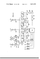
- FIG. 3 is a diagrammatic illustration of an embodiment of a control device according to the invention.
- FIGS. 4 to 6 relate to another embodiment in which the temperature of the metal at the upper part of the mould is measured by a differential measurement using two associated sensors, FIG. 4 showing the arangement of the two associated temperature sensors, FIG. 5 showing the corresponding modification of FIG. 3, and FIG. 6 showing the variations in the temperatures detected by the two sensors.
- the sensors 5 and 6 are for measuring the temperatures T1 and T2 of the mould itself and the sensor 7 measures the temperature T3 at the upper part of the mould.
- the sensor 8 measures the temperature T5 at the inlet or runner of the mould.
- potentiometers 11, 12 and 13 the rest voltage U 0 being taken from potentiometer 11, the holding voltage U 1 , corresponding to the formation of the skin, being taken from potentiometer 12, and the voltage U 2 , corresponding to the full pressure during solidification, being taken from potentiometer 13.
- the voltages U 0 and U 2 are connected directly to an analog switch 15 which governs the thyristor control 16 for the supply voltage of electromagnetic pump 17.
- the voltage U 1 is connected to the switch 15 by means of a digital-to-analog converter 18 driven by a clock counter 19.
- the clock counter 19 determines the duration of the stage t1 by setting a number N1 of impulses originating from a time base 20.
- the preset number N1 is transmitted by means of the connection 22 to the converter 18 and defines the number of stages of progression necessary to produce the voltage U 1 when counting has ended.
- Each counting step of the counter 19, which is actuated by a circuit-breaking input 23, is transmitted by means of connection 24 and increases by one stage the voltage which is transmitted by the converter 18 to the switch 15.
- the output signal when counting has ended which corresponds to the production of the full voltage U 1 on the switch 15, is transmitted by connection 25 to the switch 15 to start the holding of the voltage U 1 during the second stage t2.
- the signal actuates a counter 27 by connection 26, and the zeroing of the counter 19 by means of connection 28.
- the counter 27 determines the duration of the stage t2 by presetting a number N2 of impulses originating from the same time base 20.
- the signal actuates counter 35 by connection 33 and the zeroing of the counter 27 by connection 36.
- the counter 35 determines the duration of the stage t3 by presetting a number N3 of impulses originating from a time base 38.
- the signal actuates counter 45 by connection 44 and the zeroing of the counter 35 by connection 46.
- the counter 45 determines the duration of the last stage t4 by presetting a number N4 of impulses originating from a time base 51.
- the output signal from the counter 45 when counting has ended, which corresponds to the end of complementary solidification stage t4, it transmitted by connection 47 to a relay 48 of a device 49 for controlling opening of the mould.
- the signal actuates the zeroing of the counter 45 by connection 50.
- the device which has been described corresponds virtually to a known device, in which the duration of the four stages of the cycle is fixed solely by setting the indices N1, N2, N3 and N4.
- temperature measurements are involved in the control. As shown, the temperatures are measured by the thermocouples 5, 6, 7 and 8 located on the mould as shown in FIG. 1, and by a thermocouple 55 for measuring the temperature of the metal in the melting furnace.
- the signal from the thermocouple 55 which represents the temperature T 0 of the metal in the furnace, is introduced into the negative feedback circuit of an amplifier 57 in order to reverse the effect of the temperature variation.
- the mean signal from the thermocouples 5 and 6 which represents the mean of the temperatures T2 and T3 recorded on the mould and, consequently, the mean value of the temperature of the mould, is introduced into the negative feedback circuit of an amplifier 59 in order also to reverse the effect of the temperature variation.
- the outputs of the amplifiers 57 and 59 are applied, via loading resistors 60 and 61, to the circuit for controlling the time base 20 which drives the counters 19 and 27.
- the control of the time base 20 will be changed so as to shorten the period of the impulses.
- a reduction in the absolute duration of the counting will result, that is to say the same number of stages of progression of the voltage U 1 will be obtained but in a shorter time, and the progression of the rate of introduction of the metal into the mould will be increased.
- the duration of the stage t2 for holding the voltage at U 1 will be shortened by reducing the duration of the elementary impulses counted in the counter 27.
- thermocouple 7 which represents the temperature T3
- the signal from the thermocouple 7, which represents the temperature T3 is applied to a threshold detector 62 which is set to output when the temperature T3 reaches the solidication temperature of the metal.
- the detection signal from detector 62 is applied by connection 64 to the input of the OR gate 31 in parallel with the signal from the counter 27 when counting has ended.
- thermocouple 7 it is therefore possible to use the counter 27 only as a safety means, in order to instruct the switch 15 to proceed to stage t3 only if detection of the solidication has not occurred by thermocouple 7 or detector 62.
- advantage will thus be taken of all the factors which can lead, for example, to an acceleration of solidification, in order to reduce the stage t2 accordingly and, in effect, to reduce the total casting cycle.
- thermocouple 8 which represents the temperature T5
- T5 the temperature at the runner
- the signal from the thermocouple 8 which represents the temperature T5
- T5 the temperature at the runner
- the detection signal is applied by connection 67 to the input of the OR gate 41, in parallel with the signal from the counter 35 when counting has ended.
- the counter 35 it is possible for the counter 35 to be used only as a safety means. In normal operation, advantage will be taken of all the factors which make it possible to reduce the duration of the stage t3 and, in effect, the duration of the total casting cycle.
- the duration of the last stage t4 for the end of solidification is also automatically set so as to take account of the actual casting conditions, in such a way that it follows a reverse pattern to that of the temperature of the mould, because the solidification will be the more rapid, the lower is the temperature of the mould.
- the measurement of the mean tamperature of the mould by means of the thermocouples 5 and 6 is therefore used.
- the signal representing the mean of the measured temperatures T2 and T3 is introduced into the negative feedback circuit of an amplifier 70 to reverse the effect of temperature variations.
- the output from the amplifier 70 is applied, via a loading resistor 71, to the circuit for controlling the time base 51 which drives the counter 45.
- a decrease in the temperature of the mould will therefore result in a reduction in the period of the impulses counted at 45 and, for the same set number N4, it will lead to a reduction in the duration of the stage t4 which is terminated by opening the mould.
- each of the counters 19 and 27, which determine the stages t1 and t2, with its own time base instead of using the same time base. It would thus be possible, for example, to apply a different degree of correction to each of the two stages.
- thermocouple 7 is replaced by two thermocouples 75 and 76, arranged at slightly staggered heights, with the upper thermocouple 76 being slightly more set back from the mould cavity (FIG. 4).
- the thermocouples 75 and 76 respectively record temperatures T3 and T4.
- the curves in FIG. 6 represent the change in the temperatures T3 and T4 during a casting operation, and it is seen that T4 is always slightly behind T3.
- thermocouples If these two thermocouples are connected in opposition on a differential measuring apparatus, the latter will detect a voltage in one direction for the rising part of the curve, a zero near the peak where the two curves of T3 and T4 intersect, and then a reversed voltage in the descending part of the curve.
- the skin begins to form inside the mould when the temperature begins to decrease. It is therefore when the differential measuring apparatus reaches zero that the end of the stage t2 will be actuated.
- the threshold detector 62 is replaced by a zero detector.
Landscapes
- Engineering & Computer Science (AREA)
- Physics & Mathematics (AREA)
- General Physics & Mathematics (AREA)
- Automation & Control Theory (AREA)
- Mechanical Engineering (AREA)
- Molds, Cores, And Manufacturing Methods Thereof (AREA)
- Injection Moulding Of Plastics Or The Like (AREA)
- Dental Prosthetics (AREA)
- Casting Support Devices, Ladles, And Melt Control Thereby (AREA)
- Manufacture Of Alloys Or Alloy Compounds (AREA)
- Encapsulation Of And Coatings For Semiconductor Or Solid State Devices (AREA)
- Continuous Casting (AREA)
Applications Claiming Priority (2)
| Application Number | Priority Date | Filing Date | Title |
|---|---|---|---|
| FR7718395 | 1977-06-15 | ||
| FR7718395A FR2394347A1 (fr) | 1977-06-15 | 1977-06-15 | Procede et dispositif de regulation d'une operation de coulee basse pression |
Publications (1)
| Publication Number | Publication Date |
|---|---|
| US4213494A true US4213494A (en) | 1980-07-22 |
Family
ID=9192138
Family Applications (1)
| Application Number | Title | Priority Date | Filing Date |
|---|---|---|---|
| US05/915,209 Expired - Lifetime US4213494A (en) | 1977-06-15 | 1978-06-13 | Process and apparatus for low pressure casting |
Country Status (10)
| Country | Link |
|---|---|
| US (1) | US4213494A (enExample) |
| JP (1) | JPS54112330A (enExample) |
| AU (1) | AU517724B2 (enExample) |
| CA (1) | CA1101099A (enExample) |
| CH (1) | CH627388A5 (enExample) |
| DE (1) | DE2826060C3 (enExample) |
| FR (1) | FR2394347A1 (enExample) |
| GB (1) | GB1598385A (enExample) |
| IT (1) | IT7868212A0 (enExample) |
| NO (1) | NO781780L (enExample) |
Cited By (13)
| Publication number | Priority date | Publication date | Assignee | Title |
|---|---|---|---|---|
| US4469164A (en) * | 1981-05-15 | 1984-09-04 | Toyota Jidosha Kogyo Kabushiki Kaisha | Method of and apparatus for inspecting the quality of a casting produced by a die-casting machine |
| US4493362A (en) * | 1982-05-27 | 1985-01-15 | Ex-Cell-O Corporation | Programmable adaptive control method and system for die-casting machine |
| US4585050A (en) * | 1981-01-05 | 1986-04-29 | Etude Et Developpement En Metallurgie, E.D.E.M., S.A.R.L. | Process for automatic regulation of a casting cycle |
| US4590987A (en) * | 1983-03-10 | 1986-05-27 | Outboard Marine Corporation | Method and apparatus for determining flow pattern of molten metal casting charge |
| US4714102A (en) * | 1986-01-11 | 1987-12-22 | Toshiba Machine Co., Ltd. | Casting method and an apparatus therefor |
| US4976305A (en) * | 1987-12-01 | 1990-12-11 | Honda Giken Kogyo Kabushiki Kaisha | Method of and apparatus for controlling die temperature in low-pressure casting process |
| US4990059A (en) * | 1988-12-19 | 1991-02-05 | Aluminum Company Of America | Method for filtering liquid-phase metals |
| US5178203A (en) * | 1992-06-11 | 1993-01-12 | Cmi International, Inc. | Apparatus for the countergravity casting of metals |
| US5215141A (en) * | 1992-06-11 | 1993-06-01 | Cmi International, Inc. | Apparatus and method for controlling the countergravity casting of molten metal into molds |
| US6298898B1 (en) * | 1999-07-06 | 2001-10-09 | Ford Global Technologies, Inc. | Optimizing cycle time and/or casting quality in the making of cast metal products |
| US6685458B2 (en) | 2001-10-11 | 2004-02-03 | Acushnet Company | Split metal die assembly with injection cycle monitor |
| US20090065170A1 (en) * | 2007-09-11 | 2009-03-12 | Honda Motor Co., Ltd. | Die cooling apparatus and method thereof |
| CN108838372A (zh) * | 2018-07-26 | 2018-11-20 | 哈尔滨工业大学 | 大型船舶铜合金螺旋桨桨毂差压铸造成型非线性加压方法 |
Families Citing this family (4)
| Publication number | Priority date | Publication date | Assignee | Title |
|---|---|---|---|---|
| EP0055947B1 (fr) * | 1981-01-05 | 1985-04-24 | ETUDE ET DEVELOPPEMENT EN METALLURGIE, E.D.E.M. Société à Responsabilité Limitée dite | Procédé et dispositif d'automatisation d'un cycle de coulée du type à basse-pression |
| GB8320298D0 (en) * | 1983-07-27 | 1983-09-01 | Pereira J A T | Apparatus for low pressure die-casting of metals |
| GB2159445B (en) * | 1984-06-02 | 1988-07-06 | Cosworth Res & Dev Ltd | Casting of metal articles |
| GB8414129D0 (en) * | 1984-06-02 | 1984-07-04 | Cosworth Res & Dev Ltd | Casting of metal articles |
Citations (3)
| Publication number | Priority date | Publication date | Assignee | Title |
|---|---|---|---|---|
| US3842893A (en) * | 1971-10-28 | 1974-10-22 | British Non Ferrous Metals Res | Method and apparatus for controlling low pressure die casting |
| JPS5143317A (ja) * | 1974-10-14 | 1976-04-14 | Honda Motor Co Ltd | Kanagatachuzoniokeru imonoreikyakujikanno seigyosochi |
| US4050503A (en) * | 1973-08-16 | 1977-09-27 | Institute Po Metaloznanie I Technologia Na Metalite | Apparatus for controlling the rate of filling of casting molds |
-
1977
- 1977-06-15 FR FR7718395A patent/FR2394347A1/fr active Granted
-
1978
- 1978-05-22 NO NO781780A patent/NO781780L/no unknown
- 1978-05-25 AU AU36475/78A patent/AU517724B2/en not_active Expired
- 1978-05-25 GB GB22804/78A patent/GB1598385A/en not_active Expired
- 1978-05-26 IT IT7868212A patent/IT7868212A0/it unknown
- 1978-06-02 JP JP6717178A patent/JPS54112330A/ja active Pending
- 1978-06-13 US US05/915,209 patent/US4213494A/en not_active Expired - Lifetime
- 1978-06-13 CH CH644978A patent/CH627388A5/fr not_active IP Right Cessation
- 1978-06-14 DE DE2826060A patent/DE2826060C3/de not_active Expired
- 1978-06-14 CA CA305,479A patent/CA1101099A/fr not_active Expired
Patent Citations (3)
| Publication number | Priority date | Publication date | Assignee | Title |
|---|---|---|---|---|
| US3842893A (en) * | 1971-10-28 | 1974-10-22 | British Non Ferrous Metals Res | Method and apparatus for controlling low pressure die casting |
| US4050503A (en) * | 1973-08-16 | 1977-09-27 | Institute Po Metaloznanie I Technologia Na Metalite | Apparatus for controlling the rate of filling of casting molds |
| JPS5143317A (ja) * | 1974-10-14 | 1976-04-14 | Honda Motor Co Ltd | Kanagatachuzoniokeru imonoreikyakujikanno seigyosochi |
Cited By (13)
| Publication number | Priority date | Publication date | Assignee | Title |
|---|---|---|---|---|
| US4585050A (en) * | 1981-01-05 | 1986-04-29 | Etude Et Developpement En Metallurgie, E.D.E.M., S.A.R.L. | Process for automatic regulation of a casting cycle |
| US4469164A (en) * | 1981-05-15 | 1984-09-04 | Toyota Jidosha Kogyo Kabushiki Kaisha | Method of and apparatus for inspecting the quality of a casting produced by a die-casting machine |
| US4493362A (en) * | 1982-05-27 | 1985-01-15 | Ex-Cell-O Corporation | Programmable adaptive control method and system for die-casting machine |
| US4590987A (en) * | 1983-03-10 | 1986-05-27 | Outboard Marine Corporation | Method and apparatus for determining flow pattern of molten metal casting charge |
| US4714102A (en) * | 1986-01-11 | 1987-12-22 | Toshiba Machine Co., Ltd. | Casting method and an apparatus therefor |
| US4976305A (en) * | 1987-12-01 | 1990-12-11 | Honda Giken Kogyo Kabushiki Kaisha | Method of and apparatus for controlling die temperature in low-pressure casting process |
| US4990059A (en) * | 1988-12-19 | 1991-02-05 | Aluminum Company Of America | Method for filtering liquid-phase metals |
| US5178203A (en) * | 1992-06-11 | 1993-01-12 | Cmi International, Inc. | Apparatus for the countergravity casting of metals |
| US5215141A (en) * | 1992-06-11 | 1993-06-01 | Cmi International, Inc. | Apparatus and method for controlling the countergravity casting of molten metal into molds |
| US6298898B1 (en) * | 1999-07-06 | 2001-10-09 | Ford Global Technologies, Inc. | Optimizing cycle time and/or casting quality in the making of cast metal products |
| US6685458B2 (en) | 2001-10-11 | 2004-02-03 | Acushnet Company | Split metal die assembly with injection cycle monitor |
| US20090065170A1 (en) * | 2007-09-11 | 2009-03-12 | Honda Motor Co., Ltd. | Die cooling apparatus and method thereof |
| CN108838372A (zh) * | 2018-07-26 | 2018-11-20 | 哈尔滨工业大学 | 大型船舶铜合金螺旋桨桨毂差压铸造成型非线性加压方法 |
Also Published As
| Publication number | Publication date |
|---|---|
| DE2826060A1 (de) | 1978-12-21 |
| DE2826060C3 (de) | 1980-08-07 |
| CA1101099A (fr) | 1981-05-12 |
| GB1598385A (en) | 1981-09-16 |
| DE2826060B2 (de) | 1979-11-29 |
| FR2394347A1 (fr) | 1979-01-12 |
| JPS54112330A (en) | 1979-09-03 |
| AU3647578A (en) | 1979-11-29 |
| IT7868212A0 (it) | 1978-05-26 |
| NO781780L (no) | 1978-12-18 |
| AU517724B2 (en) | 1981-08-20 |
| CH627388A5 (fr) | 1982-01-15 |
| FR2394347B1 (enExample) | 1980-05-09 |
Similar Documents
| Publication | Publication Date | Title |
|---|---|---|
| US4213494A (en) | Process and apparatus for low pressure casting | |
| JP3143122B2 (ja) | 温度調節システム | |
| US3642402A (en) | Injection molding process control | |
| US3842893A (en) | Method and apparatus for controlling low pressure die casting | |
| US4304287A (en) | Flow cut-off method for foundry installations | |
| US3695800A (en) | Time monitored injection molding control apparatus | |
| US4874032A (en) | Die casting controlling method | |
| US5008052A (en) | Mold clamping pressure control method for injection compression molding and injection compression molding machine | |
| KR920005438B1 (ko) | 다이 캐스팅 머시인에 있어서의 스퀴이즈 플런저 작동방법 및 그 장치 | |
| US5017315A (en) | Method and apparatus of judging quality of injection molded products | |
| US4299268A (en) | Automatically controlled casting plant | |
| JPH02204018A (ja) | 射出成形の立上げ方法および装置 | |
| US3961662A (en) | Method for controlling the rate of filling of casting molds | |
| US4050503A (en) | Apparatus for controlling the rate of filling of casting molds | |
| JPS636341B2 (enExample) | ||
| JPH0422130B2 (enExample) | ||
| DE3142141C2 (de) | Steuereinrichtung einer Druckgießmaschine | |
| JP2799454B2 (ja) | 低圧鋳造機の加圧制御方法及び加圧制御装置 | |
| JP3897397B2 (ja) | 射出成形機の射出速度制御装置 | |
| JPS6260250B2 (enExample) | ||
| JPH0340658B2 (enExample) | ||
| JPS6347119A (ja) | 可塑化制御装置 | |
| JPS5892510A (ja) | セラミツク製品の射出成形装置 | |
| JPH0356887B2 (enExample) | ||
| JPH0243559Y2 (enExample) |