US4197866A - Soil moisture sampler and controller - Google Patents
Soil moisture sampler and controller Download PDFInfo
- Publication number
- US4197866A US4197866A US05/834,778 US83477877A US4197866A US 4197866 A US4197866 A US 4197866A US 83477877 A US83477877 A US 83477877A US 4197866 A US4197866 A US 4197866A
- Authority
- US
- United States
- Prior art keywords
- energy
- moisture
- soil
- signal
- sensing
- Prior art date
- Legal status (The legal status is an assumption and is not a legal conclusion. Google has not performed a legal analysis and makes no representation as to the accuracy of the status listed.)
- Expired - Lifetime
Links
Images

Classifications
-
- G—PHYSICS
- G05—CONTROLLING; REGULATING
- G05D—SYSTEMS FOR CONTROLLING OR REGULATING NON-ELECTRIC VARIABLES
- G05D22/00—Control of humidity
- G05D22/02—Control of humidity characterised by the use of electric means
-
- A—HUMAN NECESSITIES
- A01—AGRICULTURE; FORESTRY; ANIMAL HUSBANDRY; HUNTING; TRAPPING; FISHING
- A01G—HORTICULTURE; CULTIVATION OF VEGETABLES, FLOWERS, RICE, FRUIT, VINES, HOPS OR SEAWEED; FORESTRY; WATERING
- A01G25/00—Watering gardens, fields, sports grounds or the like
- A01G25/16—Control of watering
-
- Y—GENERAL TAGGING OF NEW TECHNOLOGICAL DEVELOPMENTS; GENERAL TAGGING OF CROSS-SECTIONAL TECHNOLOGIES SPANNING OVER SEVERAL SECTIONS OF THE IPC; TECHNICAL SUBJECTS COVERED BY FORMER USPC CROSS-REFERENCE ART COLLECTIONS [XRACs] AND DIGESTS
- Y10—TECHNICAL SUBJECTS COVERED BY FORMER USPC
- Y10T—TECHNICAL SUBJECTS COVERED BY FORMER US CLASSIFICATION
- Y10T137/00—Fluid handling
- Y10T137/0318—Processes
-
- Y—GENERAL TAGGING OF NEW TECHNOLOGICAL DEVELOPMENTS; GENERAL TAGGING OF CROSS-SECTIONAL TECHNOLOGIES SPANNING OVER SEVERAL SECTIONS OF THE IPC; TECHNICAL SUBJECTS COVERED BY FORMER USPC CROSS-REFERENCE ART COLLECTIONS [XRACs] AND DIGESTS
- Y10—TECHNICAL SUBJECTS COVERED BY FORMER USPC
- Y10T—TECHNICAL SUBJECTS COVERED BY FORMER US CLASSIFICATION
- Y10T137/00—Fluid handling
- Y10T137/1842—Ambient condition change responsive
- Y10T137/1866—For controlling soil irrigation
- Y10T137/189—Soil moisture sensing
Definitions
- the invention relates generally to the field of automatic irrigation systems and more specifically, to irrigation systems which maintain the proper degree of soil moisture by measuring the soil moisture with in-ground probes and, when needed, activating irrigation sprinklers for a pre-set period of time.
- the present invention measures the physical property of heat conductivity. It is based on the natural phenomenon that air is a good heat insulator, whereas water is a good conductor of heat. Similarly, when wet a porous element of the in-ground probe dissipates heat relatively quickly, whereas when the water has been replaced by air it dissipates heat relatively slowly. The porous element, being in physical contact with the soil, has virtually the same moisture content as the soil. By comparing the heat conductivity of the porous element to a given standard, one can tell the moisture content of the soil.
- This invention fulfills the need for more sophisticated irrigation management equipment. It takes advantage of microelectronics to keep the price low, the speed with which measurements taken high, and the accuracy high.
- the system is relatively maintenance free and highly corrosion resistant. Further, the system is not effected by salinity, or other ionization conditions of the soil and under the environmental conditions of normal use would not be effected by freezing weather.
- Another advantage of the present invention is that it uses microelectronics which provide speed and accuracy at a relatively low price, freedom from maintenance, long life, and a relatively low amount of energy usage.
- Another advantage of the invention is that it can be used to test the soil only at intermittent periods. This saves power because power can be supplied to the probe for a relatively short fixed period, spaced apart by relatively large intervals. This lengthens the life of the in-ground probe, reduces power consumption, and increases measurement accuracy.
- Another advantage is that the invention is able to record moisture readings from many probes and control irrigation based on soil moisture tests on a plurality of regions in the field.
- Another advantage is that the invention is amenable to solar/storage battery powered operation. For long periods, only a timer need be powered with intermittent short periods of greater power being drawn by the sensor probe's heating element.
- Another advantage is that the invention makes checking soil moisture much simpler than in the past and removes the need for manual handling of equipment. This allows a large number of measurements at each of a large number of locations to be taken each day.
- Another advantage is that the invention irrigates for an adjustable, preselected period of time. There is no need to activate the probes to control the irrigation shutoff. If the preselected interval should supply insufficient water, the irrigation period will be repeated after the next measurement cycle.
- probes can be installed permanently in their under ground position because they are of such a long life, have such a freedom from maintenance, and are resistant to freezing.
- a timer periodically actuates the in-ground probe(s) to measure soil moisture.
- a first signal is generated by a probe at the beginning of actuation which is used as a temperature reference signal, and a second signal is generated by the probe at the end of the measurement.
- a temperature compensation circuit adjusts the second signal for the ambient temperature of the ground.
- the change in temperature is inversely proportional to the amount of moisture in the porous element of the probe, which moisture is proportional to the moisture in the soil.
- the resultant temperature corrected signal which varies inversely with the moisture level of the soil is then sent to a recording device and to a comparator.
- the recording device such as a paper strip chart, makes a physical record of the moisture and the time of the reading.
- the comparator compares the output signal to a pre-set signal indicative of the minimum soil moisture thought desirable. If the comparator finds the soil drier then the pre-set minimum, then the comparator will send out a signal which activates a timer. The timer in turn controls a valve in the irrigation line. The timer will hold the valve open for a preselected period of time.
- a scanner enables the system to take moisture readings from a plurality of probes.
- FIG. 1 is a block diagram illustrating the soil moisture sampler/controller system
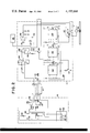
- FIG. 2 is a schematic diagram illustrating a second embodiment of the sampler/controller system with the circuitry in more detail.
- scanning means 9 controls the sampling of soil mositure at a plurality of test points determined by probes 16, 16', 16", buried in the ground at several points around the field or orchard.
- a sample rate timer 10 times the interval between actuations of the in-ground probes.
- the sample rate timer 10 may be adjustable, although a timed period of one-half hour between subsequent measurements at the same probe has been found to be very convenient, especially when the system is used with a means for permanently recording the moisture measurement. However, longer or shorter intervals may be used.
- Timer 10 periodically actuates a second timer 12 which is a sensor heater and temperature compensation circuit timer. Although timer 12 is illustrated as part of the scanner, it could also be located in the in-ground probe.
- Timer 12 through zero control circuit 14 actuates the temperature compensation circuit 24 and at the same time starts the actuation of the soil moisture testing in the in-ground probe 16.
- the first output signal from soil moisture sensor 18 which is indicative of the temperature of the probe is amplified by amplifiers 20 and 22 and stored by the temperature compensation circuit 24.
- timer 12 actuates a heater in the soil moisture sensor 18 for a fixed period of time, for example 150 seconds.
- a signal indicative of its temperature is read by the temperature compensation circuit 24.
- the temperature increase in soil moisture sensor 18 is indicative of the moisture of the soil. The more moist the soil, the greater the rate at which the heat is dissipated from the heating element.
- Temperature compensation circuit 24 then subtracts the first temperature from the second temperature to give the net temperature increase for the given period. Circuit 24 produces a voltage analog signal indicative of net temperature increase which also indicates the moisture of the soil.
- Optional amplifier 25 calibrates the output temperature compensation 24 to a convenient amplitude. For example, the output voltage amplifier 25 in volts equals the soil moisture tested in bars--1 volt equals 1 bar, 1/2 volt equals 1/2 bar, etc.
- Index circuit 11 selects the probe to be used.
- the signals may be selectively transmitted through index circuit by using a multiposition relay, or by using solid state gate elements in conjunction with a stepping register or counter which is stepped by timer 10 or timer 12 or a clock pulse generator or by the actuation of the preceding gate element, or using any one of the many circuitry combinations which are readily apparent.
- the index circuit 11 connects the output of timer 12 to one or more of the in-ground probes 16 and the output of a selected probe to the recorder and comparator circuit.
- the index circuit can be used so that timer 12 sequentially actuates one probe at a time with that probe's output being connected to the recorder and comparator. Other actuation orders are readily apparent, for example, timer 12 can actuate the heater elements of all in-ground probes simultaneously and sample the probe outputs in rapid succession.
- timer 10 may be eliminated in some modes of operation. For example, if timer 12 actuates each heater coil for 150 seconds and if one wishes to sample each of twenty probes once every 30 minutes, then timer 12 and index circuit 11 can be set up to sample the probes sequentially each immediately upon the termination of sampling the preceding probe.
- the output signal from each probe goes via the index circuit to both a soil moisture recorder 26 and comparator 28.
- the soil moisture recorder may be a strip chart recorder, such as the Watertech 1500.
- Comparator 28 compares the voltage analog signal from the temperature compensation circuit 24, with the voltage from an irrigation set point circuit 30. If the signal indicates that the soil is drier than that set on the irrigation set point circuit 30, comparator 28 sends a digital signal pulse to irrigation timer 32.
- Irrigation timer 32 in the preferred embodiment, is a digitally programmed timing device. In some instances, irrigation periods up to 10 hours have been found desirable, but normally shorter periods of 0 to 4 hours used.
- Digital timer 32 operates solenoid valve 34 in the irrigation line.
- Timer 32 holds solenoid valve 34 open for the fixed preselected period of time.
- a two state valve can be used so that a first pulse from timer 32 puts valve 34 in its open state and later pulse returns the valve to its closed state.
- the output signal from comparator 28 to timer 32 can also be gated through scanner 9 so that 2 or more irrigation line control valves similar to 34 can be controlled by the system. Although there could be one or more control valves for each probe, more normally there are many more probes than control valves.
- FIG. 2 describes a similar system in more detail. For simplicity, only one in-ground probe is illustrated, but this system can be adapted to handle several probes by merely adding an indexing circuit as shown in FIG. 1.
- a sample rate timer 110 is the basic timing unit for control unit 11. Base timer 110 can be set to provide an output pulse periodically, for example every half hour, to initiate the operation of a measurement cycle. The output pulse from timer 110 is connected to the input of a timing means 112. When timer 112 is actuated, it sends out a signal which puts transistors 114 and 120 in their conductive states. Transistor 114, when actuated by timer 112, allows current to flow through heater control line 116. Current flowing through this line flows through in-ground conduit 111 to resistance heater 118 of the in-ground probe 16.
- timer 112 The same output from timer 112 also turns on transistor 120, which in turn activates relay 122. These two transistors 114 and 120 and their associated systems stay actuated for the period of time fixed by the second timer, for example 150 seconds.
- In-ground probe 16 can be the matric potential sensor probe 1001A or 1002A made by Watertech of High Point, North Carolina.
- the probe includes a sensing means, such as diodes 124 and 126 along with energy supplying means such as a resistance heater 118 are encapsulated in transfer means such as a small porous ceramic rod 128.
- the sensing means senses the energy level temperature, of the transfer means at least before and after the energy supplying means supplies a known quantum of energy to the transfer means.
- Rod 128, being porous, absorbs water from the soil and has a moisture content proportional to that of the surrounding soil.
- Diode 126 compensates the sensor for ambient soil temperature changes while diode 124 measures the temperature rise at the center of the ceramic rod when electric current is passed through resistance heater 118.
- the temperature rise that takes place is inverse to the moisture content inside the ceramic rod. The greater the moisture within the ceramic rod the greater is the amount of heat absorbed by the water and the smaller is the temperature rise.
- the temperature is measured by diode 124 and diode 126 by the change in forward voltage drop with respect to temperature for a silicon diode. For the diodes used in Watertech probes 1001A and 1002A, this change will be approximately 2.2 millivolts per degree centigrade.
- Resistors 130-133 form with the diodes the basic elements of a Wheatstone bridge. Resistors 131 and 132 balance the current through diodes 124 and 126, allowing, in the preferred embodiment, approximately one milliamp of current to flow through each diode.
- Resistors 134-137 form the feedback components necessary to set the gain of amplifier 138, for example to a gain of 100.
- the amplifier 138 is connected with rod 128 for under ground installation to take advantage of the slow temperature changes under ground when the unit is installed at depths greater than six inches.
- Diodes 124 and 126 must be matched for proper temperature tracking capability. Also, the initial forward voltage drop of diodes 124 and 126 must match in order to prevent saturation of amplifier 138.
- the output signal of amplifier 138 in analog voltage form is fed to amplifier 140 where it is amplified a second time, e.g. another 10 times. From there, the voltage signal goes to a differential amplifier 142 and on into storage means 144.
- Storage means 144 may be, for example, a 0.68 MFD capacitor.
- the differential amplifier 142 acts as a combining means for subtractively combining the signal from the probe with the signal from the storage means to form an adjusted signal which is the difference between the voltage input from amplifier 140 and the voltage stored in the capacitor 144.
- the voltage representative of the difference between the starting and finishing voltages, i.e., temperature, of the diode 124 in the sensor probe is fed to a comparing means 146 and to recorder 26.
- Amplifier 140, differential amplifier 142, and storage capacitor 144 may, optionally, be built into the in-ground probe 16.
- Comparator 146 compares a reference signal from differential amplifier 142 with the voltage from an adjustable set point control 30.
- the voltage of set point control 30 may be produced by using a variable resistor as a voltage divider.
- the comparator converts the signal from an analog to a digital signal. If the voltage from circuit 142 exceeds the voltage from set point control 30, then comparator 146 provides an output pulse to digital timer 148.
- Digital timer 148 may be programed with an eight bit mini dip switch. For example, the time may be programmable from 55 seconds to 14,025 seconds. Timer 148 acts to bias transistor 150 into its conducting mode for the pre-set period of time.
- Transistor 150 controls a relay 152, which in turn controls the solenoid valve 34 in the irrigation line.
- Relay 152 may control irrigation in other ways such as controlling a water pump.
- this scanner could gate the output signals of comparator 146 to a plurality of irrigation control means in FIG. 2. Further, the scanner could program timer 148 for different times for different probes and/or irrigation lines. The correspondence of probes to irrigation lines will, of course, be dictated by the physical arrangement of the irrigation lines and placement of the probes.
Abstract
Description
Claims (14)
Priority Applications (1)
| Application Number | Priority Date | Filing Date | Title |
|---|---|---|---|
| US05/834,778 US4197866A (en) | 1977-09-19 | 1977-09-19 | Soil moisture sampler and controller |
Applications Claiming Priority (1)
| Application Number | Priority Date | Filing Date | Title |
|---|---|---|---|
| US05/834,778 US4197866A (en) | 1977-09-19 | 1977-09-19 | Soil moisture sampler and controller |
Publications (1)
| Publication Number | Publication Date |
|---|---|
| US4197866A true US4197866A (en) | 1980-04-15 |
Family
ID=25267783
Family Applications (1)
| Application Number | Title | Priority Date | Filing Date |
|---|---|---|---|
| US05/834,778 Expired - Lifetime US4197866A (en) | 1977-09-19 | 1977-09-19 | Soil moisture sampler and controller |
Country Status (1)
| Country | Link |
|---|---|
| US (1) | US4197866A (en) |
Cited By (45)
| Publication number | Priority date | Publication date | Assignee | Title |
|---|---|---|---|---|
| US4256133A (en) * | 1977-08-22 | 1981-03-17 | Coward Noel D | Watering valve device |
| US4385452A (en) * | 1981-06-03 | 1983-05-31 | Whirlpool Corporation | Low voltage sensor for dryer |
| US4396149A (en) * | 1980-12-30 | 1983-08-02 | Energy Management Corporation | Irrigation control system |
| US4548225A (en) * | 1981-09-28 | 1985-10-22 | Busalacchi Dwight J | Irrigation control system |
| EP0202847A2 (en) * | 1985-05-17 | 1986-11-26 | The Standard Oil Company | System and method for Scheduling irrigation |
| WO1987000725A1 (en) * | 1985-08-05 | 1987-02-12 | Wolfe Donald J Jr | Center pivot irrigation system |
| US4657039A (en) * | 1984-08-30 | 1987-04-14 | Ranya L. Alexander | Moisture sensor |
| US4693419A (en) * | 1981-11-02 | 1987-09-15 | Water Sentry, Inc. | Automatic control apparatus and method for sprinkling water over a predetermined area |
| US4785843A (en) * | 1988-02-29 | 1988-11-22 | Nicholson Laurence R | Multiplexed automatic control system |
| US4837499A (en) * | 1986-05-19 | 1989-06-06 | Scherer Iii Robert P | Moisture sensing device |
| GB2211320A (en) * | 1987-10-21 | 1989-06-28 | Tung Kung Chao | A soil moisture controller |
| GB2225520A (en) * | 1988-12-02 | 1990-06-06 | Colin Draper | Control of irrigation water supply |
| US4952868A (en) * | 1986-05-19 | 1990-08-28 | Scherer Iii Robert P | Moisture sensing system for an irrigation system |
| US5042294A (en) * | 1988-07-11 | 1991-08-27 | Ken Uzzell | Moisture detection probe |
| US5148826A (en) * | 1991-09-03 | 1992-09-22 | Behrooz Bakhshaei | Moisture monitoring and control system |
| US5207380A (en) * | 1992-02-26 | 1993-05-04 | Frank Harryman | Irrigation control system |
| US5287734A (en) * | 1992-02-13 | 1994-02-22 | Cuming Kenneth J | Thermal sensor |
| US5337957A (en) * | 1993-07-01 | 1994-08-16 | Olson Troy C | Microprocessor-based irrigation system with moisture sensors in multiple zones |
| US5355122A (en) * | 1992-07-24 | 1994-10-11 | Erickson Gary A | Rainfall detection and disable control system |
| GB2281419A (en) * | 1993-06-22 | 1995-03-01 | Kenneth Crawshaw | An irrigation system |
| US5430384A (en) * | 1994-07-22 | 1995-07-04 | Onset Computer Corp. | Temperature compensated soil moisture sensor |
| US5464044A (en) * | 1994-08-05 | 1995-11-07 | Brinkerhoff; Joseph M. | Sprinkler system controller |
| FR2735328A1 (en) * | 1995-06-15 | 1996-12-20 | Rain Bird Europ Sarl | Pre-programmed automatic plant watering controller |
| WO1997008942A1 (en) * | 1995-09-07 | 1997-03-13 | Smart Rain Corp. Inc. | Control system for the irrigation of watering stations |
| US5749521A (en) * | 1996-05-22 | 1998-05-12 | Lore Parker | Moisture sensing electronic irrigation control |
| US5859536A (en) * | 1997-01-08 | 1999-01-12 | Oliver Haugen | Moisture sensor having low sensitivity to conductance changes |
| US5878447A (en) * | 1997-10-24 | 1999-03-09 | Wkr Productions, Inc. | Automatic water regulator apparatus for filling a swimming pool or comparable body of water when the water level is low |
| US5927603A (en) * | 1997-09-30 | 1999-07-27 | J. R. Simplot Company | Closed loop control system, sensing apparatus and fluid application system for a precision irrigation device |
| US6377181B1 (en) | 2001-02-05 | 2002-04-23 | Dryvit Systems, Inc. | Method and apparatus for moisture detection in exterior sheathing of residential and commercial buildings |
| US20030222783A1 (en) * | 2002-05-28 | 2003-12-04 | Mark Amacher | Moisture detection and location system |
| US20050087620A1 (en) * | 2003-10-27 | 2005-04-28 | Bowers John R. | Moisture sensor sprinkler control systems |
| DE10355368A1 (en) * | 2003-11-25 | 2005-06-23 | Henkel Kgaa | humidity measurement |
| US20050218244A1 (en) * | 2002-06-17 | 2005-10-06 | Landcare Research New Zealand Limited | Soil moisture content measurement system and method |
| US20050240313A1 (en) * | 2004-05-10 | 2005-10-27 | Cartwright Brent A | Digital moisture monitor controller with wide applications soil and hydroponics moisture sensors and optional X10 multi sensor multi pump controller |
| US20060139037A1 (en) * | 2004-12-28 | 2006-06-29 | Hughes William C | Soil probe device and method of making same |
| US7130757B2 (en) | 2003-12-03 | 2006-10-31 | Jeld-Wen, Inc. | Remote monitoring system |
| US20070044378A1 (en) * | 2005-08-31 | 2007-03-01 | Blouin John P | Plant watering, conservation and improvement control system |
| US20080013437A1 (en) * | 2005-01-13 | 2008-01-17 | International Business Machines Corporation | Probe for scanning over a substrate and a data storage device |
| US20080302002A1 (en) * | 2005-11-23 | 2008-12-11 | Plantcare Ag | Watering System for Watering Plants |
| US20100076610A1 (en) * | 2008-09-19 | 2010-03-25 | Vuong Binh Hong | Low cost automatic sprinkler assistant |
| US8302881B1 (en) * | 2009-02-02 | 2012-11-06 | Green Badge, LLC | Method and system for soil and water resources |
| US20160183484A1 (en) * | 2014-11-03 | 2016-06-30 | MorpH2O Water Management, LLC | Soil Moisture Probe and System |
| CN106909182A (en) * | 2017-03-24 | 2017-06-30 | 中国矿业大学(北京) | A kind of soil temperature and humidity monitoring of ore deposit refuse dump and Intelligentized regulating and controlling system |
| US20190320601A1 (en) * | 2018-04-18 | 2019-10-24 | Agrome Inc. | Robotic agricultural irrigation and analysis system |
| US10968589B2 (en) * | 2014-01-13 | 2021-04-06 | Charlie J. Schafer | Water monitoring and control system and method thereof |
Citations (5)
| Publication number | Priority date | Publication date | Assignee | Title |
|---|---|---|---|---|
| US2718141A (en) * | 1952-01-25 | 1955-09-20 | Lorenzo A Richards | Electro-thermal element for measuring moisture in porous media |
| US3626286A (en) * | 1968-11-20 | 1971-12-07 | George P Rauchwerger | Capacitive moisture control system having a peak detector |
| US3777976A (en) * | 1973-03-29 | 1973-12-11 | S Milovancevic | Electronically controlled watering |
| US3847351A (en) * | 1973-06-29 | 1974-11-12 | H Hasenbeck | Soil matric potential sensor |
| US3882383A (en) * | 1973-06-07 | 1975-05-06 | Charles Matlin | Soil moisture sensing system |
-
1977
- 1977-09-19 US US05/834,778 patent/US4197866A/en not_active Expired - Lifetime
Patent Citations (5)
| Publication number | Priority date | Publication date | Assignee | Title |
|---|---|---|---|---|
| US2718141A (en) * | 1952-01-25 | 1955-09-20 | Lorenzo A Richards | Electro-thermal element for measuring moisture in porous media |
| US3626286A (en) * | 1968-11-20 | 1971-12-07 | George P Rauchwerger | Capacitive moisture control system having a peak detector |
| US3777976A (en) * | 1973-03-29 | 1973-12-11 | S Milovancevic | Electronically controlled watering |
| US3882383A (en) * | 1973-06-07 | 1975-05-06 | Charles Matlin | Soil moisture sensing system |
| US3847351A (en) * | 1973-06-29 | 1974-11-12 | H Hasenbeck | Soil matric potential sensor |
Non-Patent Citations (7)
| Title |
|---|
| McCune-Neal Brochure for Matric Potential Measurement System 2002A, 1971, High Point, N.C. * |
| McCune-Neal Brochure for Matric Potential Sensor Probes 1001A, 1002A, 1971, High Point, N.C. * |
| Phene, C. J. et al. Controlling Automated Irrigation with a Soil Matric Potential Sensor, U.S. Salinity Laboratory, Riverside, Calif. (published prior to Jul., 1976). * |
| Phene, C. J. et al. Controlling Automated Irrigation with Soil Matric Potential Sensor, Trans. Amer. Soc. Agr. Eng., vol. 16, No. 4, 773-776, 1973. * |
| Phene, C. J. et al. Measuring Soil Matric Potential in situ by Sensing Heat Dissipation Within a Porous Body: I. Theory and Sensor Construction, Soil Science Society of America Proceedings, vol. 35, No. 1, Jan.-Feb. 1971. * |
| Phene, C. J. et al. Measuring Soil Matric Potential in situ by Sensing Heat Dissipation Within a Porous Body: II. Experimenta Results, Soil Sci. Amer. Proc., vol. 35, No. 2, Mar.-Apr., 1971. * |
| Watertech Brochure, 1976, 6 pages (Model 2002B on cover) Watertech, Trinity, N.C. * |
Cited By (67)
| Publication number | Priority date | Publication date | Assignee | Title |
|---|---|---|---|---|
| US4256133A (en) * | 1977-08-22 | 1981-03-17 | Coward Noel D | Watering valve device |
| US4396149A (en) * | 1980-12-30 | 1983-08-02 | Energy Management Corporation | Irrigation control system |
| US4385452A (en) * | 1981-06-03 | 1983-05-31 | Whirlpool Corporation | Low voltage sensor for dryer |
| US4548225A (en) * | 1981-09-28 | 1985-10-22 | Busalacchi Dwight J | Irrigation control system |
| US4693419A (en) * | 1981-11-02 | 1987-09-15 | Water Sentry, Inc. | Automatic control apparatus and method for sprinkling water over a predetermined area |
| US4657039A (en) * | 1984-08-30 | 1987-04-14 | Ranya L. Alexander | Moisture sensor |
| EP0202847A2 (en) * | 1985-05-17 | 1986-11-26 | The Standard Oil Company | System and method for Scheduling irrigation |
| EP0202847A3 (en) * | 1985-05-17 | 1987-06-16 | The Standard Oil Company | System and method for scheduling irrigation |
| US4755942A (en) * | 1985-05-17 | 1988-07-05 | The Standard Oil Company | System for indicating water stress in crops which inhibits data collection if solar insolation exceeds a range from an initial measured value |
| WO1987000725A1 (en) * | 1985-08-05 | 1987-02-12 | Wolfe Donald J Jr | Center pivot irrigation system |
| US4837499A (en) * | 1986-05-19 | 1989-06-06 | Scherer Iii Robert P | Moisture sensing device |
| US4952868A (en) * | 1986-05-19 | 1990-08-28 | Scherer Iii Robert P | Moisture sensing system for an irrigation system |
| GB2211320A (en) * | 1987-10-21 | 1989-06-28 | Tung Kung Chao | A soil moisture controller |
| US4785843A (en) * | 1988-02-29 | 1988-11-22 | Nicholson Laurence R | Multiplexed automatic control system |
| US5042294A (en) * | 1988-07-11 | 1991-08-27 | Ken Uzzell | Moisture detection probe |
| GB2225520A (en) * | 1988-12-02 | 1990-06-06 | Colin Draper | Control of irrigation water supply |
| US5148826A (en) * | 1991-09-03 | 1992-09-22 | Behrooz Bakhshaei | Moisture monitoring and control system |
| US5287734A (en) * | 1992-02-13 | 1994-02-22 | Cuming Kenneth J | Thermal sensor |
| US5207380A (en) * | 1992-02-26 | 1993-05-04 | Frank Harryman | Irrigation control system |
| US5355122A (en) * | 1992-07-24 | 1994-10-11 | Erickson Gary A | Rainfall detection and disable control system |
| GB2281419B (en) * | 1993-06-22 | 1997-06-04 | Kenneth Crawshaw | An irrigation system |
| GB2281419A (en) * | 1993-06-22 | 1995-03-01 | Kenneth Crawshaw | An irrigation system |
| US5337957A (en) * | 1993-07-01 | 1994-08-16 | Olson Troy C | Microprocessor-based irrigation system with moisture sensors in multiple zones |
| US5430384A (en) * | 1994-07-22 | 1995-07-04 | Onset Computer Corp. | Temperature compensated soil moisture sensor |
| US5464044A (en) * | 1994-08-05 | 1995-11-07 | Brinkerhoff; Joseph M. | Sprinkler system controller |
| FR2735328A1 (en) * | 1995-06-15 | 1996-12-20 | Rain Bird Europ Sarl | Pre-programmed automatic plant watering controller |
| ES2121534A2 (en) * | 1995-06-15 | 1998-11-16 | Rain Bird Europ Sarl | Pre-programmed automatic plant watering controller |
| WO1997008942A1 (en) * | 1995-09-07 | 1997-03-13 | Smart Rain Corp. Inc. | Control system for the irrigation of watering stations |
| WO1997009612A1 (en) * | 1995-09-07 | 1997-03-13 | Smart Rain Corp. Inc. | Water content, salinity and texture sensor of porous media |
| US5740031A (en) * | 1995-09-07 | 1998-04-14 | Smart Rain Corp. Inc. | Control system for the irrigation of watering stations |
| US5749521A (en) * | 1996-05-22 | 1998-05-12 | Lore Parker | Moisture sensing electronic irrigation control |
| US5859536A (en) * | 1997-01-08 | 1999-01-12 | Oliver Haugen | Moisture sensor having low sensitivity to conductance changes |
| US5927603A (en) * | 1997-09-30 | 1999-07-27 | J. R. Simplot Company | Closed loop control system, sensing apparatus and fluid application system for a precision irrigation device |
| US5878447A (en) * | 1997-10-24 | 1999-03-09 | Wkr Productions, Inc. | Automatic water regulator apparatus for filling a swimming pool or comparable body of water when the water level is low |
| US6377181B1 (en) | 2001-02-05 | 2002-04-23 | Dryvit Systems, Inc. | Method and apparatus for moisture detection in exterior sheathing of residential and commercial buildings |
| US20020130781A1 (en) * | 2001-02-05 | 2002-09-19 | Kroll Richard E. | Method and apparatus for moisture detection in exterior sheathing of residential and commercial buildings |
| US7126486B2 (en) | 2001-02-05 | 2006-10-24 | Dryvit Systems, Inc. | Method and apparatus for moisture detection in exterior sheathing of residential and commercial buildings |
| US6995676B2 (en) | 2002-05-28 | 2006-02-07 | Mark Amacher | Moisture detection and location system |
| US20030222783A1 (en) * | 2002-05-28 | 2003-12-04 | Mark Amacher | Moisture detection and location system |
| US7222519B2 (en) | 2002-06-17 | 2007-05-29 | Landcare Research New Zealand Limited | Soil moisture content measurement system and method |
| US20050218244A1 (en) * | 2002-06-17 | 2005-10-06 | Landcare Research New Zealand Limited | Soil moisture content measurement system and method |
| US7063270B2 (en) * | 2003-10-27 | 2006-06-20 | Bowers John R | Moisture sensor sprinkler control systems |
| US20050087620A1 (en) * | 2003-10-27 | 2005-04-28 | Bowers John R. | Moisture sensor sprinkler control systems |
| DE10355368A1 (en) * | 2003-11-25 | 2005-06-23 | Henkel Kgaa | humidity measurement |
| US20090287447A1 (en) * | 2003-12-03 | 2009-11-19 | Jeld-Wen, Inc. | Remote Monitoring System |
| US7574320B2 (en) | 2003-12-03 | 2009-08-11 | Jeld-Wen, Inc. | Remote monitoring system |
| US7130757B2 (en) | 2003-12-03 | 2006-10-31 | Jeld-Wen, Inc. | Remote monitoring system |
| US8694277B2 (en) | 2003-12-03 | 2014-04-08 | Jeld-Wen, Inc. | Remote monitoring system |
| US20070093982A1 (en) * | 2003-12-03 | 2007-04-26 | Jeld-Wen, Inc. | Remote monitoring system |
| US20090287457A1 (en) * | 2003-12-03 | 2009-11-19 | Jeld-Wen, Inc. | Remote Monitoring System |
| US20050240313A1 (en) * | 2004-05-10 | 2005-10-27 | Cartwright Brent A | Digital moisture monitor controller with wide applications soil and hydroponics moisture sensors and optional X10 multi sensor multi pump controller |
| US20060139037A1 (en) * | 2004-12-28 | 2006-06-29 | Hughes William C | Soil probe device and method of making same |
| US7183779B2 (en) | 2004-12-28 | 2007-02-27 | Spectrum Technologies, Inc. | Soil probe device and method of making same |
| US7482826B2 (en) * | 2005-01-13 | 2009-01-27 | International Business Machines Corporation | Probe for scanning over a substrate and a data storage device |
| US20080013437A1 (en) * | 2005-01-13 | 2008-01-17 | International Business Machines Corporation | Probe for scanning over a substrate and a data storage device |
| US20070044378A1 (en) * | 2005-08-31 | 2007-03-01 | Blouin John P | Plant watering, conservation and improvement control system |
| US20080302002A1 (en) * | 2005-11-23 | 2008-12-11 | Plantcare Ag | Watering System for Watering Plants |
| US20100076610A1 (en) * | 2008-09-19 | 2010-03-25 | Vuong Binh Hong | Low cost automatic sprinkler assistant |
| US8302881B1 (en) * | 2009-02-02 | 2012-11-06 | Green Badge, LLC | Method and system for soil and water resources |
| US8366017B1 (en) * | 2009-02-02 | 2013-02-05 | Green Badge, LLC | Method and system for soil and water resources |
| US10968589B2 (en) * | 2014-01-13 | 2021-04-06 | Charlie J. Schafer | Water monitoring and control system and method thereof |
| US20160183484A1 (en) * | 2014-11-03 | 2016-06-30 | MorpH2O Water Management, LLC | Soil Moisture Probe and System |
| US9949450B2 (en) * | 2014-11-03 | 2018-04-24 | MorpH2O Water Management, LLC | Soil moisture probe and system with temperature adjustment |
| CN106909182B (en) * | 2017-03-24 | 2018-04-13 | 中国矿业大学(北京) | A kind of soil temperature and humidity monitoring of ore deposit refuse dump and Intelligentized regulating and controlling system |
| CN106909182A (en) * | 2017-03-24 | 2017-06-30 | 中国矿业大学(北京) | A kind of soil temperature and humidity monitoring of ore deposit refuse dump and Intelligentized regulating and controlling system |
| US20190320601A1 (en) * | 2018-04-18 | 2019-10-24 | Agrome Inc. | Robotic agricultural irrigation and analysis system |
| US10856476B2 (en) * | 2018-04-18 | 2020-12-08 | Agrome Inc. | Robotic agricultural irrigation and analysis system |
Similar Documents
| Publication | Publication Date | Title |
|---|---|---|
| US4197866A (en) | Soil moisture sampler and controller | |
| US5621669A (en) | Moisture sensor probe and control mechanism | |
| US4952868A (en) | Moisture sensing system for an irrigation system | |
| Benyon | Nighttime water use in an irrigated Eucalyptus grandis plantation | |
| US4837499A (en) | Moisture sensing device | |
| Lundblad et al. | Evaluation of heat balance and heat dissipation methods for sapflow measurements in pine and spruce | |
| US3771548A (en) | Capacitive moisture control system having a peak detector | |
| US4155252A (en) | Wind energy metering and recording systems | |
| US3626286A (en) | Capacitive moisture control system having a peak detector | |
| Buchan | Soil temperature regime | |
| US8924031B1 (en) | Irrigation scheduling and supervisory control and data acquisition system for moving and static irrigation systems | |
| US11310970B2 (en) | Method of determination of water stress in a one or more plants in a crop located in the vicinity of a soil moisture sensor array and knowledge of ETo | |
| US20220248617A1 (en) | Method of Determination of Water Stress in a One or More Plants in a Crop Located in the region of a Soil Moisture Sensor Array and Knowledge of ETo | |
| Mahan et al. | Agricultural applications of a low-cost infrared thermometer | |
| Dangare et al. | Design, fabrication and testing of a low cost Trunk Diameter Variation (TDV) measurement system based on an ATmega 328/P microcontroller | |
| Walker et al. | Stress Measurement Using Foliage Temperatures 1 | |
| Bailey et al. | Bulk stomatal resistance control on evaporation | |
| Jones et al. | Evaluation of various heat-pulse methods for estimation of sap flow in orchard trees: comparison with micrometeorological estimates of evaporation | |
| Long | Instruments for micro‐meteorology | |
| CN113267643A (en) | Trunk liquid flow non-invasive measurement device and method suitable for plant thin stems | |
| Saddler et al. | An apparatus for the measurement of sap flow in unexcised leafy shoots | |
| Kolapkar et al. | Design and development of embedded system for measurement of humidity, soil moisture and temperature in polyhouse using 89e516rd microcontroller | |
| Sutton et al. | Electronic monitoring and use of microprocessors in the field | |
| JP3035262B2 (en) | Moisture sensor, moisture measuring device, and water supply method using the same | |
| WO2019023108A1 (en) | Cost-effective real-time tree water status monitoring system for irrigation management and stress detection |
Legal Events
| Date | Code | Title | Description |
|---|---|---|---|
| AS | Assignment |
Owner name: NAIONAL CITY BANK Free format text: SECURITY INTEREST;ASSIGNOR:HANCOR, INC. A CORP. OF OH.;REEL/FRAME:004684/0176 Effective date: 19860422 Owner name: HANCOR, INC. Free format text: RELEASED BY SECURED PARTY;ASSIGNOR:NATIONAL CITY BANK, AS AGENT;REEL/FRAME:004684/0172 Effective date: 19860422 |
|
| AS | Assignment |
Owner name: NATIONAL CITY BANK Free format text: SECURITY INTEREST;ASSIGNOR:HANCOR, INC., A CORP. OF OH;REEL/FRAME:005404/0116 Effective date: 19900713 |
|
| AS | Assignment |
Owner name: NATIONAL CITY BANK, OHIO Free format text: SECOND AMENDED AND RESTATED COLLATERAL ASSIGNMENT OF PATENTS;ASSIGNOR:HANCOR, INC.;REEL/FRAME:006331/0651 Effective date: 19920923 |