US4164102A - Process for the manufacture of a ceramic axial turbine wheel - Google Patents
Process for the manufacture of a ceramic axial turbine wheel Download PDFInfo
- Publication number
- US4164102A US4164102A US05/762,520 US76252077A US4164102A US 4164102 A US4164102 A US 4164102A US 76252077 A US76252077 A US 76252077A US 4164102 A US4164102 A US 4164102A
- Authority
- US
- United States
- Prior art keywords
- profile
- machined
- blade
- tool means
- straight lines
- Prior art date
- Legal status (The legal status is an assumption and is not a legal conclusion. Google has not performed a legal analysis and makes no representation as to the accuracy of the status listed.)
- Expired - Lifetime
Links
- 238000000034 method Methods 0.000 title claims abstract description 37
- 239000000919 ceramic Substances 0.000 title claims abstract description 25
- 238000004519 manufacturing process Methods 0.000 title claims abstract description 20
- 238000003754 machining Methods 0.000 claims abstract description 25
- 238000009760 electrical discharge machining Methods 0.000 claims abstract description 16
- 230000003628 erosive effect Effects 0.000 claims description 6
- 230000010355 oscillation Effects 0.000 abstract description 4
- 239000011796 hollow space material Substances 0.000 abstract description 2
- 239000000463 material Substances 0.000 description 6
- 238000010276 construction Methods 0.000 description 3
- OKTJSMMVPCPJKN-UHFFFAOYSA-N Carbon Chemical compound [C] OKTJSMMVPCPJKN-UHFFFAOYSA-N 0.000 description 2
- 230000006978 adaptation Effects 0.000 description 2
- 230000007246 mechanism Effects 0.000 description 2
- 238000012986 modification Methods 0.000 description 2
- 230000004048 modification Effects 0.000 description 2
- 238000007493 shaping process Methods 0.000 description 2
- 239000003082 abrasive agent Substances 0.000 description 1
- 229910052799 carbon Inorganic materials 0.000 description 1
- 229910010293 ceramic material Inorganic materials 0.000 description 1
- 239000010437 gem Substances 0.000 description 1
- 229910052732 germanium Inorganic materials 0.000 description 1
- GNPVGFCGXDBREM-UHFFFAOYSA-N germanium atom Chemical compound [Ge] GNPVGFCGXDBREM-UHFFFAOYSA-N 0.000 description 1
- 239000011521 glass Substances 0.000 description 1
- 239000008187 granular material Substances 0.000 description 1
- 239000010439 graphite Substances 0.000 description 1
- 229910002804 graphite Inorganic materials 0.000 description 1
- 229910052751 metal Inorganic materials 0.000 description 1
- 239000002184 metal Substances 0.000 description 1
- 150000002739 metals Chemical class 0.000 description 1
- 229920001296 polysiloxane Polymers 0.000 description 1
- 239000007787 solid Substances 0.000 description 1
- 239000000725 suspension Substances 0.000 description 1
- 238000009210 therapy by ultrasound Methods 0.000 description 1
- 229910000859 α-Fe Inorganic materials 0.000 description 1
Images


Classifications
-
- B—PERFORMING OPERATIONS; TRANSPORTING
- B23—MACHINE TOOLS; METAL-WORKING NOT OTHERWISE PROVIDED FOR
- B23P—METAL-WORKING NOT OTHERWISE PROVIDED FOR; COMBINED OPERATIONS; UNIVERSAL MACHINE TOOLS
- B23P15/00—Making specific metal objects by operations not covered by a single other subclass or a group in this subclass
- B23P15/02—Making specific metal objects by operations not covered by a single other subclass or a group in this subclass turbine or like blades from one piece
-
- Y—GENERAL TAGGING OF NEW TECHNOLOGICAL DEVELOPMENTS; GENERAL TAGGING OF CROSS-SECTIONAL TECHNOLOGIES SPANNING OVER SEVERAL SECTIONS OF THE IPC; TECHNICAL SUBJECTS COVERED BY FORMER USPC CROSS-REFERENCE ART COLLECTIONS [XRACs] AND DIGESTS
- Y10—TECHNICAL SUBJECTS COVERED BY FORMER USPC
- Y10T—TECHNICAL SUBJECTS COVERED BY FORMER US CLASSIFICATION
- Y10T29/00—Metal working
- Y10T29/49—Method of mechanical manufacture
- Y10T29/49316—Impeller making
- Y10T29/4932—Turbomachine making
- Y10T29/49321—Assembling individual fluid flow interacting members, e.g., blades, vanes, buckets, on rotary support member
Definitions
- the present invention relates to a method for the manufacture of a ceramic axial turbine wheel from an electrically conductive or electrically non-conductive ceramic mass with the aid of spark erosion or supersonic machining and with the aid of cylindrical work tools used in connection therewith and matched correspondingly to the desired profile blade shape.
- the two profile surfaces i.e., the pressure side and the suction side of the profile
- a cylindrical shaping or profiling tool which has a larger machining cross section than corresponds to the final intended profile cross section at each cross-sectional place of the respective blades and which initially is moved past the one profile surface composed of inclined straight lines as well as is pivoted thereby corresponding to the inclination of the generating straight lines and then is moved past the other profile surface also composed of inclined straight lines and is thereby pivoted corresponding to the inclination of the generating straight lines, whereby the larger width of the profiling tool which is larger compared to the final profile, results from the magnitude of the pivoting action.
- the profile vane or blade edges after the forming of the profile surfaces, can be machined with different tools by means of an ultrasonic apparatus or by means of a spark erosion apparatus or also mechanically by hand. A shaping or profiling tool can also be used for that purpose.
- turbine wheels cannot only be made according to the methods described so far hereinabove but can also be manufactured according to a slightly modified method by working or machining the blades by means of spark erosion or ultrasonics.
- This modified method according to the present invention is characterized in that respectively a pressure side and the suction side disposed opposite thereto are machined or worked simultaneously by means of a single tool which is matched to the desired profile shape on the two machining sides and is introduced or fed radially with respect to the turbine wheel into the hollow space to be machined between respectively two profile blade surfaces to be machined, whereby the work tool carries out the oscillations necessary for the spark erosion or ultrasonic treatment.
- the profiling tool may be rotated during its radial introduction and while it carries out the machining oscillations.
- the method according to the present invention can be carried out by means of a work tool which is adapted to be mounted at the ultrasonic apparatus or at the spark erosion apparatus and is constructed in its working area approximately wedge-shaped as well as in such a manner that it fits into the intermediate space which remains between two adjacent blades of a finished turbine wheel, and that its working surfaces are matched to the respectively oppositely disposed surfaces of adjacent blades whereas, as to the rest, it includes a hilt or haft adapted to be inserted into the work tool holder of the ultrasonic or spark erosion apparatus.
- Another object of the present invention resides in a method for the manufacture of ceramic axial turbine wheels which not only greatly facilitates their manufacture with the aid of spark erosion or ultrasonic apparatus but increases the operating efficiency of the finished turbine.
- a further object of the present invention resides in a method of the type described above which permits the manufacture of twisted ceramic blades, especially twisted conical blades.
- Still a further object of the present invention resides in a method for the manufacture of ceramic axial turbine wheels which greatly simplifies the manufacturing operations, yet eliminates the limitations, heretofore imposed by the prior art methods, as regards the shapes of the blades.
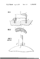
- FIG. 1 is a cross-sectional view through a workpiece with a work tool of an ultrasonic borer in accordance with the present invention which has already partly penetrated into the workpiece;
- FIG. 2 is a cross-sectional view through the work tool according to line II--II of FIG. 1;
- FIG. 3 is a side elevational view of a prior art turbine blade seated on a turbine wheel hub
- FIG. 4 is a cross-sectional view through the turbine wheel taken along line IV--IV of FIG. 3;
- FIG. 5 is an attempted schematic illustration of a turbine blade in accordance with the present invention whose twisted profile surfaces are formed by straight lines disposed adjacent one another;
- FIG. 6 is a plan view illustrating the congruence of the head and base cross section of the pressure side profile surface in accordance with the present invention.
- FIG. 7 is a plan view illustrating the congruence of the head and base cross section of the suction side profile surface of a turbine blade in accordance with the present invention.
- FIG. 8 is a somewhat schematic elevational view of a modified embodiment of an erosion machining tool in accordance with the present invention for manufacturing an axial turbine blade.
- FIG. 9 is a somewhat schematic elevational view illustrative of a modified method in accordance with the present invention utilizing the tool of FIG. 8.
- ultrasonic boring techniques can be used with electrically non-conductive, brittle-hard materials.
- this method is not applicable to ductile-hard materials.
- Brittle-hard materials are glass, ceramics, precious stones, silicone, germanium, carbon, graphite, ferrites and in some cases also hard metals.
- turbine wheels as indicated above, can be manufactured from ceramic materials with high heat resistance, the ultrasonic working or machining techniques are the correct method in order to manufacture turbine blades in the manner according to the present invention also with twisted profile surfaces.
- FIG. 1 A side elevational view and partially a cross section through the workpiece with the work tool already partly penetrated into the same of an ultrasonic machining apparatus of otherwise conventional construction is illustrated in FIG. 1 which operates vertically with about 22 kHz in a conventional manner.
- the workpiece 1 is gradually hollowed-out by the work tool 2 within the area of the cross-sectional profile of the work tool 2 illustrated in FIG. 2 as a result of the applied high oscillations.
- the cylindrical boring tool 2 therefore does not rotate but oscillates accurately in the feed direction. It therefore also need not be round but instead has the profile of the bore to be produced.
- the turbine wheel is positioned and adjusted anew and is mounted on the pivotal apparatus (not shown) in such a manner that now the profile lines of the suction side 11 become also congruent in this case as they pass the working or machining surface 12 of the tool.
- the resulting profile has been machined with a sufficiently large clear gap about the profile so that the ultrasonic apparatus no longer removes anything on the already machined pressure side from the pressure surface disposed thereat which has already been finish-machined.
- the blade profiles are machined in this manner, then the residual portions 13 to 16 still remain at the respective deflection edges of the profiles.
- the same can be removed by means of a further ultrasonic manual apparatus, which involves no great difficulty since the blade profiles only have a very slight dimension of about 1 to 2 cm. and the parts to be removed are only very small as regards volume.
- An ultrasonic machine with several ultrasonic heads of conventional construction may also be used for an economic series-manufacture so that correspondingly several profiles can be manufactured simultaneously.
- Ceramic blades can be manufactured in a similar manner by spark erosion if the blank consists of an electrically conductive ceramic mass.
- FIG. 9 illustrates a partially machined turbine wheel 101 which is being manufactured according to a modified method of the present invention.
- two turbine blades 102 have already been manufactured completely and two turbine blades 103 have already been manufactured partly.
- the turbine blades are worked or machined by means of the work tool generally designated by reference numeral 104 which includes wedge-shaped working areas 105, by means of which it is introduced into the intermediate spaces remaining between two turbine blades.
- the work tool 104 includes a hilt or handle 106 by means of which it is inserted into the work tool holder of the ultrasonic and spark erosion apparatus.
- the wedge-shaped working area 105 and the turbine wheel are moved toward one another (as represented by the arrow on tool 104), whereby with a turned-on ultrasonic or spark erosion apparatus, the intermediate space between two turbine blades is being machined out in each case (it is noted that tool 104 is exaggerated in size relative to turbine wheel 101 in FIG. 9 and in acutality, working area 105 is smaller than the resultant gap between the finished blades).
- the turbine wheel is further rotated through one pitch and then the work piece is introduced again for machining out the next intermediate space, until successively all turbine blades have been manufactured.
Landscapes
- Engineering & Computer Science (AREA)
- Mechanical Engineering (AREA)
- Turbine Rotor Nozzle Sealing (AREA)
- Processing Of Stones Or Stones Resemblance Materials (AREA)
- Grinding And Polishing Of Tertiary Curved Surfaces And Surfaces With Complex Shapes (AREA)
Applications Claiming Priority (4)
| Application Number | Priority Date | Filing Date | Title |
|---|---|---|---|
| DE2603226 | 1976-01-29 | ||
| DE19762603226 DE2603226A1 (de) | 1976-01-29 | 1976-01-29 | Verfahren und vorrichtung zur herstellung eines keramischen axialturbinenrades |
| DE19762627309 DE2627309A1 (de) | 1976-06-18 | 1976-06-18 | Verfahren und vorrichtung zur herstellung eines keramischen turbinenrades |
| DE2627309 | 1976-06-18 |
Publications (1)
| Publication Number | Publication Date |
|---|---|
| US4164102A true US4164102A (en) | 1979-08-14 |
Family
ID=25769975
Family Applications (1)
| Application Number | Title | Priority Date | Filing Date |
|---|---|---|---|
| US05/762,520 Expired - Lifetime US4164102A (en) | 1976-01-29 | 1977-01-26 | Process for the manufacture of a ceramic axial turbine wheel |
Country Status (2)
| Country | Link |
|---|---|
| US (1) | US4164102A (en:Method) |
| JP (1) | JPS5293412A (en:Method) |
Cited By (7)
| Publication number | Priority date | Publication date | Assignee | Title |
|---|---|---|---|---|
| US4866829A (en) * | 1982-05-31 | 1989-09-19 | Ngk Insulators, Ltd. | Method of producing a ceramic rotor |
| US5163987A (en) * | 1985-05-07 | 1992-11-17 | Sumitomo Electric Industries, Ltd. | Method for producing glass preform for optical fiber |
| US5191711A (en) * | 1991-12-23 | 1993-03-09 | Allied-Signal Inc. | Compressor or turbine blade manufacture |
| US5193311A (en) * | 1989-06-24 | 1993-03-16 | T&N Technology Limited | Tools for working non-metallic hard materials |
| US20050170762A1 (en) * | 2002-10-17 | 2005-08-04 | Kostar Timothy D. | Method and apparatus for ultrasonic machining |
| US9737933B2 (en) | 2012-09-28 | 2017-08-22 | General Electric Company | Process of fabricating a shield and process of preparing a component |
| US9890647B2 (en) | 2009-12-29 | 2018-02-13 | Rolls-Royce North American Technologies Inc. | Composite gas turbine engine component |
Citations (10)
| Publication number | Priority date | Publication date | Assignee | Title |
|---|---|---|---|---|
| US353551A (en) * | 1886-11-30 | Fertilizer-distributer | ||
| US1568746A (en) * | 1926-01-05 | F lawaczeck x | ||
| US2429324A (en) * | 1943-12-30 | 1947-10-21 | Meisser Christian | Rotor for centrifugal compressors |
| US2461948A (en) * | 1944-10-09 | 1949-02-15 | Bristol Aeroplane Co Ltd | Honing or the like machine |
| US2633776A (en) * | 1948-08-14 | 1953-04-07 | Kellogg M W Co | Method of manufacturing turbine blades integral with turbine rotor |
| US2729422A (en) * | 1951-04-06 | 1956-01-03 | Maschf Augsburg Nuernberg Ag | Shaped article of ceramic material |
| US2767460A (en) * | 1950-02-08 | 1956-10-23 | Robbins Engineering Company | Turbine blade and method of making same |
| US3091060A (en) * | 1957-07-12 | 1963-05-28 | Lehfeldt & Company G M B H Dr | Ultrasonic machining |
| US3863399A (en) * | 1974-03-15 | 1975-02-04 | Oakley Cowdrick | Apparatus for finishing a foil |
| US3897171A (en) * | 1974-06-25 | 1975-07-29 | Westinghouse Electric Corp | Ceramic turbine rotor disc and blade configuration |
-
1977
- 1977-01-26 US US05/762,520 patent/US4164102A/en not_active Expired - Lifetime
- 1977-01-29 JP JP826577A patent/JPS5293412A/ja active Granted
Patent Citations (10)
| Publication number | Priority date | Publication date | Assignee | Title |
|---|---|---|---|---|
| US353551A (en) * | 1886-11-30 | Fertilizer-distributer | ||
| US1568746A (en) * | 1926-01-05 | F lawaczeck x | ||
| US2429324A (en) * | 1943-12-30 | 1947-10-21 | Meisser Christian | Rotor for centrifugal compressors |
| US2461948A (en) * | 1944-10-09 | 1949-02-15 | Bristol Aeroplane Co Ltd | Honing or the like machine |
| US2633776A (en) * | 1948-08-14 | 1953-04-07 | Kellogg M W Co | Method of manufacturing turbine blades integral with turbine rotor |
| US2767460A (en) * | 1950-02-08 | 1956-10-23 | Robbins Engineering Company | Turbine blade and method of making same |
| US2729422A (en) * | 1951-04-06 | 1956-01-03 | Maschf Augsburg Nuernberg Ag | Shaped article of ceramic material |
| US3091060A (en) * | 1957-07-12 | 1963-05-28 | Lehfeldt & Company G M B H Dr | Ultrasonic machining |
| US3863399A (en) * | 1974-03-15 | 1975-02-04 | Oakley Cowdrick | Apparatus for finishing a foil |
| US3897171A (en) * | 1974-06-25 | 1975-07-29 | Westinghouse Electric Corp | Ceramic turbine rotor disc and blade configuration |
Cited By (11)
| Publication number | Priority date | Publication date | Assignee | Title |
|---|---|---|---|---|
| US4866829A (en) * | 1982-05-31 | 1989-09-19 | Ngk Insulators, Ltd. | Method of producing a ceramic rotor |
| US5163987A (en) * | 1985-05-07 | 1992-11-17 | Sumitomo Electric Industries, Ltd. | Method for producing glass preform for optical fiber |
| US5193311A (en) * | 1989-06-24 | 1993-03-16 | T&N Technology Limited | Tools for working non-metallic hard materials |
| US5191711A (en) * | 1991-12-23 | 1993-03-09 | Allied-Signal Inc. | Compressor or turbine blade manufacture |
| US5544873A (en) * | 1991-12-23 | 1996-08-13 | Alliedsignal Inc. | Apparatus to hold compressor or turbine blade during manufacture |
| US20050170762A1 (en) * | 2002-10-17 | 2005-08-04 | Kostar Timothy D. | Method and apparatus for ultrasonic machining |
| US7497764B2 (en) * | 2002-10-17 | 2009-03-03 | General Electric Company | Method and apparatus for ultrasonic machining |
| US9890647B2 (en) | 2009-12-29 | 2018-02-13 | Rolls-Royce North American Technologies Inc. | Composite gas turbine engine component |
| EP2519437B1 (en) * | 2009-12-29 | 2018-11-28 | Rolls-Royce North American Technologies, Inc. | Composite gas turbine engine component |
| US9737933B2 (en) | 2012-09-28 | 2017-08-22 | General Electric Company | Process of fabricating a shield and process of preparing a component |
| US10828701B2 (en) | 2012-09-28 | 2020-11-10 | General Electric Company | Near-net shape shield and fabrication processes |
Also Published As
| Publication number | Publication date |
|---|---|
| JPS5432006B2 (en:Method) | 1979-10-11 |
| JPS5293412A (en) | 1977-08-05 |
Similar Documents
| Publication | Publication Date | Title |
|---|---|---|
| EP1430983B1 (de) | Verfahren zur Formgebung durch elektrochemisches Abtragen | |
| US7827883B1 (en) | Cutting die and method of forming | |
| US6575674B2 (en) | Reaming tool and process for its production | |
| US8500518B2 (en) | Method of grinding an indexable insert and grinding wheel for carrying out the grinding method | |
| DE3911986A1 (de) | Verfahren und vorrichtung zur formgebenden bearbeitung von werkstuecken | |
| EP0038929B1 (de) | Abrichtwerkzeug | |
| US2286874A (en) | Method of making pinking shears | |
| US4164102A (en) | Process for the manufacture of a ceramic axial turbine wheel | |
| US2144987A (en) | Method for making cutter blades | |
| US4639991A (en) | Process for producing a new edge on an airfoil blade particularly the fan blade for a gas turbine engine | |
| EP1330339B1 (en) | Method and apparatus for making a cutting tool having a plurality of margins | |
| CN113770670B (zh) | 一种pcd立铣刀及其加工方法 | |
| EP1322448B1 (en) | Method and apparatus for making a cutting tool having a flute | |
| JPH0129641B2 (en:Method) | ||
| US4144678A (en) | Method for resharpening cutting blades for gear cutting machinery | |
| US4015509A (en) | Method and apparatus for shaping an airfoil | |
| GB2542124B (en) | Method and tools for manufacturing a bladed disk | |
| JPH0465739B2 (en:Method) | ||
| US4550497A (en) | Tool to produce a new angle on a fan blade | |
| US4608756A (en) | Tool to produce a new leading edge on a fan blade | |
| EP0327657A1 (de) | Verfahren zum Herstellen eines Schaufelrades | |
| JPH0929530A (ja) | ラフィングエンドミル | |
| GB2205513A (en) | Manufacture of form cutting tool tip | |
| CN87203994U (zh) | 四刃四点导向套料刀 | |
| US20200338643A1 (en) | Controlled fracture machining method for producing through-holes |