US4154136A - Drum pitch control assembly - Google Patents
Drum pitch control assembly Download PDFInfo
- Publication number
- US4154136A US4154136A US05/881,903 US88190378A US4154136A US 4154136 A US4154136 A US 4154136A US 88190378 A US88190378 A US 88190378A US 4154136 A US4154136 A US 4154136A
- Authority
- US
- United States
- Prior art keywords
- drum
- body portion
- tension
- drum head
- adjusting ring
- Prior art date
- Legal status (The legal status is an assumption and is not a legal conclusion. Google has not performed a legal analysis and makes no representation as to the accuracy of the status listed.)
- Expired - Lifetime
Links
- 230000002093 peripheral effect Effects 0.000 claims 2
- 230000007246 mechanism Effects 0.000 abstract description 3
- 241000208967 Polygala cruciata Species 0.000 description 6
- 230000009471 action Effects 0.000 description 2
- 238000010276 construction Methods 0.000 description 2
- 230000000694 effects Effects 0.000 description 2
- 230000000712 assembly Effects 0.000 description 1
- 238000000429 assembly Methods 0.000 description 1
- 230000008859 change Effects 0.000 description 1
- 238000007373 indentation Methods 0.000 description 1
- 239000003550 marker Substances 0.000 description 1
- 239000002184 metal Substances 0.000 description 1
- 230000004048 modification Effects 0.000 description 1
- 238000012986 modification Methods 0.000 description 1
- 230000000007 visual effect Effects 0.000 description 1
Images

Classifications
-
- G—PHYSICS
- G10—MUSICAL INSTRUMENTS; ACOUSTICS
- G10D—STRINGED MUSICAL INSTRUMENTS; WIND MUSICAL INSTRUMENTS; ACCORDIONS OR CONCERTINAS; PERCUSSION MUSICAL INSTRUMENTS; AEOLIAN HARPS; SINGING-FLAME MUSICAL INSTRUMENTS; MUSICAL INSTRUMENTS NOT OTHERWISE PROVIDED FOR
- G10D13/00—Percussion musical instruments; Details or accessories therefor
- G10D13/10—Details of, or accessories for, percussion musical instruments
- G10D13/16—Tuning devices; Hoops; Lugs
-
- G—PHYSICS
- G10—MUSICAL INSTRUMENTS; ACOUSTICS
- G10D—STRINGED MUSICAL INSTRUMENTS; WIND MUSICAL INSTRUMENTS; ACCORDIONS OR CONCERTINAS; PERCUSSION MUSICAL INSTRUMENTS; AEOLIAN HARPS; SINGING-FLAME MUSICAL INSTRUMENTS; MUSICAL INSTRUMENTS NOT OTHERWISE PROVIDED FOR
- G10D13/00—Percussion musical instruments; Details or accessories therefor
- G10D13/01—General design of percussion musical instruments
- G10D13/02—Drums; Tambourines with drumheads
Definitions
- the present invention relates in general to a pitch control assembly for a musical drum, and more specifically to such assemblies that are disposed on the exterior of the drums on which they are employed.
- the present invention provides a pitch control assembly that operates on a cam action principle and in that respect falls in the same general class as that of the Newberry and Hull inventions.
- the structure of the present invention is entirely different from that disclosed by Newberry and Hull so as to provide a pitch control assembly that is simple to manipulate and efficient in operation to easily and quickly effect precise tension adjustments.
- the present invention provides a pitch control assembly for a musical drum that includes an open ended cylindrical body portion, a drum head covering one of the open ends of said body portion and connected at its periphery to a flesh hoop, and a drum head tension band for engaging the flesh hoop.
- the control assembly includes a rotatable tension adjusting ring encircling the drum body portion and having a plurality of circumferentially spaced apart cam surfaces, means for limiting movement of the adjusting ring toward the drum head, a plurality of means connecting the tension band to the adjusting ring, each of which has a portion in coacting engagement with an associated cam surface of the adjusting ring, and adjusting means connected to the adjusting ring and the drum body portion for adjustably rotating the adjusting ring.
- the movement limiting means consists of a plurality of abutment means mounted circumferentially about the exterior of said drum body portion for engagement with a lateral annular flange on the adjusting ring.
- the connecting means of the preferred embodiment is formed of a plurality of adjustable members connected to the tension ring and having vertically moveable follower members engageable with the cam surfaces of the adjusting ring. As the adjusting ring is rotated about its axis the follower members are moved by the cam surfaces, thereby to control adjustment of the drum head tension.
- FIG. 1 is a perspective view of a drum having the pitch control assembly of the present invention in assembly relation therewith;
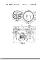
- FIG. 2 is a plan view of the drum of FIG. 1;
- FIG. 3 is an enlarged detail side view as seen along line 3--3 in FIG. 2;
- FIG. 4 is a sectional view taken on line 4--4 of FIG. 3;
- FIG. 5 is a sectional view taken on line 5--5 of FIG. 3;
- FIG. 6 is a sectional view on line 6--6 of FIG. 3;
- FIG. 7 is an enlarged perspective view of a journal member included in the pitch control assembly of FIG. 1.
- the present invention is adapted to serve as a pitch control assembly for a musical drum and is indicated generally at 10 in FIG. 1 in association with a drum 11.
- the drum 11 includes a cylindrical body portion 12 that is open at its opposite ends 13 and 14.
- Drum heads 18 and 19 cover each of the open ends 13 and 14, respectively, and are attached at their peripheries to flesh hoops 20 and 20a, also respectively, that fit snugly about the drum body portion ends 13 and 14.
- Tension bands 21 and 22, having outwardly projecting annular flange portions 23 and 24, respectively, for engaging the peripheries of the flesh hoops 20 and 20a, are connected to the body portion 12 to apply an axially directed pressure on the flesh hoops 20 and 20a, whereby to place the drum heads 18 and 19 under tension.
- the tension band 21 is connected in a usual manner to the drum body portion 12 by means of a plurality of circumferentially spaced bolts 25 extended through the flange 23 for threaded engagement with associated lugs 26 fixed about the drum body portion 12. Tension of the drum head 18 can, thus be varied by individually adjusting the bolts 25.
- the tension band 22 is connected to the drum body portion 12 by means including the pitch control assembly 10 in a manner to eliminate the necessity of individual adjustment of a plurality of bolts when a tension change in the drum head 19 is desired.
- the pitch control assembly 10 includes a tension adjusting ring 27 (FIG. 2) arranged in a concentrically spaced relation about the drum body portion 12, and formed from a lightweight, high strength metal.
- the ring 27 includes a band portion 28 formed with a plurality of circumferentially spaced slots 29 (FIGS. 1 and 3) which are inclined relative to the plane of the drumhead 19.
- the band portion 28 has an inwardly projected annular flange 30 (FIG. 4) on the side thereof remote from the drum head 19.
- a plurality of combination abutment and guide members 34 are circumferentially spaced about and are bolted to the exterior of the drum body portion 12 equi-distant from the drum head 19.
- Each combination member 34 has a U-shaped head portion 35 to form a guideway 36 that is open in a direction toward the drum head 19.
- the head portions 35 are positioned between the drum body portion 12 and the band portion 28 of the tension adjusting ring 27 for abutting engagement with the flange 30 and contact engagement with the inside diameter of the band portion 28. Accordingly, the head portions 35 abut against the ring band portion 28 and the ring flange 30 to position the band portion 28 whereby to concurrently maintain the tension adjusting ring 27 against movement toward the drum head 19 and concentrically spaced about the drum body portion 12.
- Each guideway 36 of the combination member 34 guidably receives a cylindrical elongated nut 37 threaded on a bolt 38 disposed through the annular flange member portion 24 on the tension band 22.
- the width of each of the guideways 36 is slightly larger than the diameter of one of the nut members 37 whereby to guidably support vertical movement of the nut members 37.
- One end of each of the cylindrical nut members 37 projects into one of the slots 29 of the tension adjusting ring 27 for bearing engagement with the upper sidewall 39 of an associated ring slot 29, thereby limiting movement of the ring 27 away from the drumhead 19.
- a nut member 37 thus functions as a cam follower member relative to the slot upper sidewall 39 which constitutes a cam section.
- the tension adjusting ring 27 is held against axial movement by the abutment of the combination members 34 and the connecting means comprised of the bolts 38 and the cylindrical nut member 37, it is permitted to rotate about its axis.
- the slots 29 are preferably cut entirely through the band portion 28 of the ring 27, such construction is not essential to the present invention and all that is necessary is that the ring 27 must have inclined protrusions or indentations that provide a surface similar to the sidewall peripheries 39 of the slots 29.
- an adjusting mechanism which includes a bracket 45 (FIGS. 3 and 5) secured to and suspended from the ring flange 28 and rotatably supporting an adjusting screw having a knurled central knob 46 and a threaded shaft 46a.
- the shaft 46a is in threaded engagement with a barrel nut 47 that is held in place by a journal member 48 (FIG. 7) bolted to the drum body portion 12.
- the shaft 46a has fixed thereto collars 51 and 52 on each side of the bracket 45, so that as the shaft 46a is threaded into or out of the barrel nut 47, the adjusting ring 27 is rotated respectively to the right or left about the longitudinal axis of the drum body portion 12 to produce relative movement of the nut members 37 in the slots 29.
- the peripheries 39 of the slots 29 are cam surfaces that coact with the nut members 37, which serve as follower members. Due to the inclined alignment of the slots 29, rotational movement of the ring 27 to the left will drive the nut members 37 downwardly thereby increasing tension on the drum head 19, whereas rotational ring movement to the right will have the opposite effect.
- a marker 49 attached to the bracket 45 is arranged to overlie a scale 50 on the journal member 48.
Landscapes
- Physics & Mathematics (AREA)
- Engineering & Computer Science (AREA)
- Acoustics & Sound (AREA)
- Multimedia (AREA)
- Electrophonic Musical Instruments (AREA)
Abstract
A pitch control assembly for adjusting the tension on a drum head of a musical drum having a cylindrical body portion with an open end covered by the drum head, a flesh hoop attached to the periphery of the drum head, and a tension band for engaging the flesh hoop to apply tension on the drum head. The control assembly includes a rotatable tension adjusting ring encircling the drum body portion and having a plurality of circumferentially spaced apart slots inclined to the plane of the drum head, a plurality of abutments on the drum body portion to hold the adjusting ring against movement toward the drum head, connecting links that connect the tension band with follower members arranged in contact engagement with sidewalls of the slots in the adjusting ring, and an adjustable mechanism connected to the adjustng ring and the drum body portion for rotatably adjusting the ring relative to the drum body portion.
Description
1. Field of the Invention
The present invention relates in general to a pitch control assembly for a musical drum, and more specifically to such assemblies that are disposed on the exterior of the drums on which they are employed.
2. Description of the Prior Art
Adjusting the tension of a drum head to vary the pitch of a standard drum has long been a tedious and inconvenient task that involves a separate adjustment of a plurality of adjustable units connected between a drumhead tension band and the body portion of the drum. In the past, various drum constructions have been proposed to make such adjustment easier. For example, U.S. Pat. Nos. 2,051,671 and 2,061,244, to Au-Miller disclose relatively elaborate arrangements that are disposed inside a drum for achieving pitch adjustment by manipulation of a single adjusting mechanism and patents to Hull and Newberry, U.S. Pat. Nos. 2,550,249, and 1,901,765 and 2,115,741, respectively, disclose the use of rotatable rings that provide a cam action to vary drum head tension.
The present invention provides a pitch control assembly that operates on a cam action principle and in that respect falls in the same general class as that of the Newberry and Hull inventions. However, the structure of the present invention is entirely different from that disclosed by Newberry and Hull so as to provide a pitch control assembly that is simple to manipulate and efficient in operation to easily and quickly effect precise tension adjustments.
The present invention provides a pitch control assembly for a musical drum that includes an open ended cylindrical body portion, a drum head covering one of the open ends of said body portion and connected at its periphery to a flesh hoop, and a drum head tension band for engaging the flesh hoop. The control assembly includes a rotatable tension adjusting ring encircling the drum body portion and having a plurality of circumferentially spaced apart cam surfaces, means for limiting movement of the adjusting ring toward the drum head, a plurality of means connecting the tension band to the adjusting ring, each of which has a portion in coacting engagement with an associated cam surface of the adjusting ring, and adjusting means connected to the adjusting ring and the drum body portion for adjustably rotating the adjusting ring.
In a preferred embodiment of the present invention, the movement limiting means consists of a plurality of abutment means mounted circumferentially about the exterior of said drum body portion for engagement with a lateral annular flange on the adjusting ring. The connecting means of the preferred embodiment is formed of a plurality of adjustable members connected to the tension ring and having vertically moveable follower members engageable with the cam surfaces of the adjusting ring. As the adjusting ring is rotated about its axis the follower members are moved by the cam surfaces, thereby to control adjustment of the drum head tension.
FIG. 1 is a perspective view of a drum having the pitch control assembly of the present invention in assembly relation therewith;
FIG. 2 is a plan view of the drum of FIG. 1;
FIG. 3 is an enlarged detail side view as seen along line 3--3 in FIG. 2;
FIG. 4 is a sectional view taken on line 4--4 of FIG. 3;
FIG. 5 is a sectional view taken on line 5--5 of FIG. 3;
FIG. 6 is a sectional view on line 6--6 of FIG. 3; and
FIG. 7 is an enlarged perspective view of a journal member included in the pitch control assembly of FIG. 1.
The present invention is adapted to serve as a pitch control assembly for a musical drum and is indicated generally at 10 in FIG. 1 in association with a drum 11.
The drum 11 includes a cylindrical body portion 12 that is open at its opposite ends 13 and 14. Drum heads 18 and 19 cover each of the open ends 13 and 14, respectively, and are attached at their peripheries to flesh hoops 20 and 20a, also respectively, that fit snugly about the drum body portion ends 13 and 14. Tension bands 21 and 22, having outwardly projecting annular flange portions 23 and 24, respectively, for engaging the peripheries of the flesh hoops 20 and 20a, are connected to the body portion 12 to apply an axially directed pressure on the flesh hoops 20 and 20a, whereby to place the drum heads 18 and 19 under tension.
The tension band 21 is connected in a usual manner to the drum body portion 12 by means of a plurality of circumferentially spaced bolts 25 extended through the flange 23 for threaded engagement with associated lugs 26 fixed about the drum body portion 12. Tension of the drum head 18 can, thus be varied by individually adjusting the bolts 25.
The tension band 22 is connected to the drum body portion 12 by means including the pitch control assembly 10 in a manner to eliminate the necessity of individual adjustment of a plurality of bolts when a tension change in the drum head 19 is desired. The pitch control assembly 10 includes a tension adjusting ring 27 (FIG. 2) arranged in a concentrically spaced relation about the drum body portion 12, and formed from a lightweight, high strength metal. The ring 27 includes a band portion 28 formed with a plurality of circumferentially spaced slots 29 (FIGS. 1 and 3) which are inclined relative to the plane of the drumhead 19. The band portion 28 has an inwardly projected annular flange 30 (FIG. 4) on the side thereof remote from the drum head 19.
To prevent movement of the tension adjusting ring 27 toward the drum head 19, a plurality of combination abutment and guide members 34 (FIG. 3) are circumferentially spaced about and are bolted to the exterior of the drum body portion 12 equi-distant from the drum head 19. Each combination member 34 has a U-shaped head portion 35 to form a guideway 36 that is open in a direction toward the drum head 19. Referring to FIG. 4, it is seen that the head portions 35 are positioned between the drum body portion 12 and the band portion 28 of the tension adjusting ring 27 for abutting engagement with the flange 30 and contact engagement with the inside diameter of the band portion 28. Accordingly, the head portions 35 abut against the ring band portion 28 and the ring flange 30 to position the band portion 28 whereby to concurrently maintain the tension adjusting ring 27 against movement toward the drum head 19 and concentrically spaced about the drum body portion 12.
Each guideway 36 of the combination member 34 guidably receives a cylindrical elongated nut 37 threaded on a bolt 38 disposed through the annular flange member portion 24 on the tension band 22. As indicated in FIG. 3, the width of each of the guideways 36 is slightly larger than the diameter of one of the nut members 37 whereby to guidably support vertical movement of the nut members 37. One end of each of the cylindrical nut members 37 projects into one of the slots 29 of the tension adjusting ring 27 for bearing engagement with the upper sidewall 39 of an associated ring slot 29, thereby limiting movement of the ring 27 away from the drumhead 19. A nut member 37 thus functions as a cam follower member relative to the slot upper sidewall 39 which constitutes a cam section. Although the tension adjusting ring 27 is held against axial movement by the abutment of the combination members 34 and the connecting means comprised of the bolts 38 and the cylindrical nut member 37, it is permitted to rotate about its axis. Although the slots 29 are preferably cut entirely through the band portion 28 of the ring 27, such construction is not essential to the present invention and all that is necessary is that the ring 27 must have inclined protrusions or indentations that provide a surface similar to the sidewall peripheries 39 of the slots 29.
To adjust the rotational movement of the tension adjusting ring 27, there is provided an adjusting mechanism which includes a bracket 45 (FIGS. 3 and 5) secured to and suspended from the ring flange 28 and rotatably supporting an adjusting screw having a knurled central knob 46 and a threaded shaft 46a. The shaft 46a is in threaded engagement with a barrel nut 47 that is held in place by a journal member 48 (FIG. 7) bolted to the drum body portion 12. The shaft 46a has fixed thereto collars 51 and 52 on each side of the bracket 45, so that as the shaft 46a is threaded into or out of the barrel nut 47, the adjusting ring 27 is rotated respectively to the right or left about the longitudinal axis of the drum body portion 12 to produce relative movement of the nut members 37 in the slots 29. The peripheries 39 of the slots 29 are cam surfaces that coact with the nut members 37, which serve as follower members. Due to the inclined alignment of the slots 29, rotational movement of the ring 27 to the left will drive the nut members 37 downwardly thereby increasing tension on the drum head 19, whereas rotational ring movement to the right will have the opposite effect.
To provide a visual indication of the tension setting of the drum head a marker 49 attached to the bracket 45 is arranged to overlie a scale 50 on the journal member 48. Thus, by simply manipulating the adjusting screw by the single control knob the control assembly of the present invention provides for a rapid, and precise adjustment of the drum head tension.
Although a single tension control assembly 10 for adjusting the drumhead 19 has been described, it is apparent that a similar second control assembly may be provided for drum head 18. Generally, however, it is only necessary to control the pitch of the drum head played upon.
Although the invention has been described with respect to a preferred embodiment thereof, it is to be understood that it is not to be so limited since changes and modifications can be made therein which are within the full intended scope of this invention as defined by the appended claims.
Claims (4)
1. A pitch control assembly for a musical drum having a tubular cylindrical body portion with open ends, a drum head covering at least one of said open ends and having a peripheral portion connected to a flesh hoop extended about said body portion, and an annular drum head tension band engageable with said flesh hoop to apply a tension on said drum head, said pitch control assembly comprising:
(a) a rotatable tension adjusting ring positioned about the body portion of said drum and formed with a plurality of circumferentially spaced cam surfaces inclined at an angle to the plane of said drum head;
(b) means for limiting axial movement of said adjusting ring toward said drum head;
(c) a plurality of means connecting said tension band with said adjusting ring, each of said connecting means having an extension member connected with said tension band and a cam follower portion adjustably disposed on said extension member and in coacting engagement with an associated cam surface of said adjusting ring; and
(d) adjustable means connected to said adjusting ring and said drum body portion for adjustably rotating said ring about the longitudinal axis of said body portion to move said cam surface relative to said cam follower to vary the tension on said drum head.
2. A pitch control assembly according to Claim 1 wherein:
(a) said movement limiting means is a plurality of abutment guide means mounted circumferentially about the exterior of said drum body portion and a flange on said adjusting ring that engages said abutment means.
3. A pitch control assembly according to claim 2, wherein:
(a) each of said abutment guide means includes a guideway for guidably supporting one of said follower members for vertical movement in response to rotation of said adjusting ring.
4. A pitch control assembly for a musical drum having a cylindrical body portion with opposite open ends, a drum head covering at least one of said open ends and having a peripheral portion connected to a flesh hoop extended about said body portion, and an annular drum head tension band engageable with said flesh hoop to apply a tension on said drum head, said pitch control assembly comprising:
(a) a plurality of abutment guide means mounted circumferentially about the exterior of said body portion and uniformly spaced from said drum head;
(b) a rotatable tension adjusting ring having a flange that engages said abutment means and is limited thereby from moving toward said drum head, said adjusting ring including a plurality of circumferentially spaced apart slots directed on an incline to the plane of said drum head;
(c) a plurality of means connecting between said tension band and said adjusting ring, each of said means having an extension member connected with said tension band and a cam follower portion adjustably disposed on said extension member and in coacting engagement with an associated slot in said adjusting ring; and
(d) adjustable means connected to said adjusting ring and said drum body portion for adjustably rotating said ring about the longitudinal axis of said body portion to vary the tension on said drum head.
Priority Applications (1)
| Application Number | Priority Date | Filing Date | Title |
|---|---|---|---|
| US05/881,903 US4154136A (en) | 1978-02-27 | 1978-02-27 | Drum pitch control assembly |
Applications Claiming Priority (1)
| Application Number | Priority Date | Filing Date | Title |
|---|---|---|---|
| US05/881,903 US4154136A (en) | 1978-02-27 | 1978-02-27 | Drum pitch control assembly |
Publications (1)
| Publication Number | Publication Date |
|---|---|
| US4154136A true US4154136A (en) | 1979-05-15 |
Family
ID=25379435
Family Applications (1)
| Application Number | Title | Priority Date | Filing Date |
|---|---|---|---|
| US05/881,903 Expired - Lifetime US4154136A (en) | 1978-02-27 | 1978-02-27 | Drum pitch control assembly |
Country Status (1)
| Country | Link |
|---|---|
| US (1) | US4154136A (en) |
Cited By (9)
| Publication number | Priority date | Publication date | Assignee | Title |
|---|---|---|---|---|
| US4295405A (en) * | 1978-10-18 | 1981-10-20 | Sleishman Donald E | Musician's drum |
| US4630521A (en) * | 1984-11-05 | 1986-12-23 | Alletto Darro F | Drum head retainer |
| US4709613A (en) * | 1986-08-18 | 1987-12-01 | Steven Powers | Variable tensioning mechanism for drum head |
| US5442988A (en) * | 1994-10-11 | 1995-08-22 | Mayo; Brett E. | Non-loosening, keyless drum tuning device |
| DE19807019A1 (en) * | 1998-02-19 | 1999-09-09 | Hallweger | Tensioning block for musical drums |
| US5977463A (en) * | 1998-06-22 | 1999-11-02 | Bartlett; Robert Orion | Tuning mechanism for a drum |
| FR2806204A1 (en) * | 2000-03-10 | 2001-09-14 | Jean Gael Vingot | Tuner for percussion musical instrument with skin has catch to connect each tension regulator to visual indicator |
| US8110730B2 (en) | 2010-06-28 | 2012-02-07 | Burdick Charles I | Keyless drum tuning device |
| US8404957B2 (en) | 2010-11-02 | 2013-03-26 | Steven S. Richards | Drum tuning apparatus |
Citations (5)
| Publication number | Priority date | Publication date | Assignee | Title |
|---|---|---|---|---|
| DE79778C (en) * | ||||
| US1284526A (en) * | 1918-05-23 | 1918-11-12 | Frederick C Claessens | Drum. |
| US2061244A (en) * | 1935-04-29 | 1936-11-17 | Cleve M Au-Miller | Unitensioned drum |
| DE697976C (en) * | 1937-12-10 | 1940-10-29 | Walter Bechstein | |
| US3439573A (en) * | 1967-09-05 | 1969-04-22 | Marco D Zottolo | Drum tuning device |
-
1978
- 1978-02-27 US US05/881,903 patent/US4154136A/en not_active Expired - Lifetime
Patent Citations (5)
| Publication number | Priority date | Publication date | Assignee | Title |
|---|---|---|---|---|
| DE79778C (en) * | ||||
| US1284526A (en) * | 1918-05-23 | 1918-11-12 | Frederick C Claessens | Drum. |
| US2061244A (en) * | 1935-04-29 | 1936-11-17 | Cleve M Au-Miller | Unitensioned drum |
| DE697976C (en) * | 1937-12-10 | 1940-10-29 | Walter Bechstein | |
| US3439573A (en) * | 1967-09-05 | 1969-04-22 | Marco D Zottolo | Drum tuning device |
Cited By (10)
| Publication number | Priority date | Publication date | Assignee | Title |
|---|---|---|---|---|
| US4295405A (en) * | 1978-10-18 | 1981-10-20 | Sleishman Donald E | Musician's drum |
| US4630521A (en) * | 1984-11-05 | 1986-12-23 | Alletto Darro F | Drum head retainer |
| US4709613A (en) * | 1986-08-18 | 1987-12-01 | Steven Powers | Variable tensioning mechanism for drum head |
| US5442988A (en) * | 1994-10-11 | 1995-08-22 | Mayo; Brett E. | Non-loosening, keyless drum tuning device |
| DE19807019A1 (en) * | 1998-02-19 | 1999-09-09 | Hallweger | Tensioning block for musical drums |
| US5977463A (en) * | 1998-06-22 | 1999-11-02 | Bartlett; Robert Orion | Tuning mechanism for a drum |
| FR2806204A1 (en) * | 2000-03-10 | 2001-09-14 | Jean Gael Vingot | Tuner for percussion musical instrument with skin has catch to connect each tension regulator to visual indicator |
| WO2001069587A1 (en) * | 2000-03-10 | 2001-09-20 | Vingot Jean Gael | Device for tuning a percussion instrument provided with skin(s) |
| US8110730B2 (en) | 2010-06-28 | 2012-02-07 | Burdick Charles I | Keyless drum tuning device |
| US8404957B2 (en) | 2010-11-02 | 2013-03-26 | Steven S. Richards | Drum tuning apparatus |
Similar Documents
| Publication | Publication Date | Title |
|---|---|---|
| US4154136A (en) | Drum pitch control assembly | |
| DE3850771T2 (en) | STAGE LIGHTING WITH VARIABLE BEAM WIDTH. | |
| US4337749A (en) | Compound bow | |
| EP3655945B1 (en) | Percussion instrument | |
| US2977065A (en) | Drag for fishing reels | |
| US4188852A (en) | Tuning system for timpani | |
| US3439573A (en) | Drum tuning device | |
| SU644367A3 (en) | Mechanism for tightening thread running off fixed thread-accumulating drum of thread feeding device | |
| US2985474A (en) | Mechanical movement device | |
| US2061244A (en) | Unitensioned drum | |
| US2433200A (en) | Percussion drum | |
| US5163563A (en) | Apparatus for sorting elongated produce, such as french beans | |
| US1647196A (en) | Meat chopper | |
| US2587310A (en) | Kettledrum | |
| US3498561A (en) | Pivoted fishing reel with brake | |
| US4742752A (en) | Drum head tensioning device | |
| JPS6033278B2 (en) | Teinpani for March | |
| US2096299A (en) | Fishing reel | |
| DE918294C (en) | Elliptical compass | |
| DE874069C (en) | Tabletop device in the form of a turntable with musical mechanism | |
| US4403721A (en) | Variable diameter drum | |
| DE4110590C2 (en) | Scanning device for a magnetic tape device | |
| DE466067C (en) | carousel | |
| SU1435202A1 (en) | Sprinkler | |
| US2609722A (en) | Drum |