US4152995A - Sewing machine having a driven feed roller - Google Patents
Sewing machine having a driven feed roller Download PDFInfo
- Publication number
- US4152995A US4152995A US05/887,554 US88755478A US4152995A US 4152995 A US4152995 A US 4152995A US 88755478 A US88755478 A US 88755478A US 4152995 A US4152995 A US 4152995A
- Authority
- US
- United States
- Prior art keywords
- feed roller
- drive
- housing
- gear
- carrier
- Prior art date
- Legal status (The legal status is an assumption and is not a legal conclusion. Google has not performed a legal analysis and makes no representation as to the accuracy of the status listed.)
- Expired - Lifetime
Links
- 238000009958 sewing Methods 0.000 title claims abstract description 31
- 239000000463 material Substances 0.000 claims abstract description 23
- 230000008878 coupling Effects 0.000 claims abstract description 13
- 238000010168 coupling process Methods 0.000 claims abstract description 13
- 238000005859 coupling reaction Methods 0.000 claims abstract description 13
- 230000010355 oscillation Effects 0.000 claims abstract description 3
- 230000007246 mechanism Effects 0.000 abstract description 8
- 238000010276 construction Methods 0.000 abstract description 2
- 230000009471 action Effects 0.000 description 5
- 239000004744 fabric Substances 0.000 description 5
- 230000000694 effects Effects 0.000 description 3
- 230000001771 impaired effect Effects 0.000 description 1
- 238000004519 manufacturing process Methods 0.000 description 1
- 230000007704 transition Effects 0.000 description 1
- 239000013598 vector Substances 0.000 description 1
Images

Classifications
-
- D—TEXTILES; PAPER
- D05—SEWING; EMBROIDERING; TUFTING
- D05B—SEWING
- D05B27/00—Work-feeding means
- D05B27/10—Work-feeding means with rotary circular feed members
- D05B27/14—Work-feeding means with rotary circular feed members rotating discontinuously
Definitions
- the invention relates in general to sewing machines and in particular to a new and useful sewing machine with a feed roller, a spring-loaded carrier carrying the feed roller and moving substantially in vertical directions, a driving wheel; arranged, with respect to the sewing direction, behind the feed roller, and which is in operating connection with a drive shaft, and a belt running over guide rollers which forms the driving connection between the feed roller and the driving wheel.
- the known sewing machines have a disadvantage that the vertical component of the driving force acting on the pulling strand of the drive belt has a disadvantageous effect on the pressure of the feed roller on the sewing material while pressure is necessary for a satisfactory feed of the sewing material.
- This has a particularly unfavorable effect when a pulling force is required for feeding the sewing material, for example, when sewing over transitions or when using cloth guiding apparatus which offer a different resistance to the sewing material at different thicknesses.
- the variable belt force necessary for carrying out these operations influences the pressure of the feed roller on the sewing material, particularly when it is necessary to maintain the normal pressure for a satisfactory feed of the sewing material.
- the pressure of the feed roller varies with changing driving requirements, the uniformity of the feeding action of this roller is impaired, and thus also the sewing result.
- the invention provides a belt drive where the pressure of the feed roller remains constant with changing driving forces.
- the guide roller for the pulling strand of the belt is rotatably secured on a rocker pivotally mounted coaxially to the driving wheel.
- the part of the strand extending between the guide roller and the driving wheel is substantially horizontal, and the rocker is connected with a carrier for the feed roller over a coupling rod whose longitudinal axis intersects the bisector of the looping angle of the belt about the guide roller substantially in the horizontal plane through the axis of rotation of the rocker.
- a sewing machine for sewing and feeding material which has a housing with a main shaft rotatable in the housing for driving the needle, and with a feed roller carrier which is mounted on a pressure rod which depends from the housing for movement upwardly and downwardly, which carries a feed roller which is rotatable thereon which engages the material to be fed, and wherein a feed roller carries a driven gear which is driven from a drive gear through a drive belt, and wherein the drive gear is intermittently driven from the main shaft, further including a connecting rod connected between the carrier and a rocker which is pivoted on the same axis as the drive gear, and which carries two guide rollers over which the drive belt is driven, and wherein the connection between the connecting rod and the rocker is such that the belt forms an engagement angle about one of the guide rollers which has a bisector which intersects the longitudinal axis of the connecting rod substantially in the horizontal plane extending through the axis of rotation of the rocker.
- a further object of the invention is to provide a sewing machine which has a drive roller which is mounted to engage the material being threaded which is connected to a drive mechanism such that there is substantially no lifting force produced by the pull of the drive belt which drives the drive roller during the feeding of the material.
- a further object of the invention is to provide a sewing machine which is simple in design, rugged in construction, and economical to manufacture.
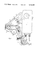
- FIG. 1 is a partial side elevational and sectional view of a feed roller drive mechanism for a sewing machine constructed in accordance with the invention.
- FIG. 2 is a schematic representation of the drive mechanism of FIG. 1 indicating the forces acting on the various parts.
- the invention embodied therein comprises a sewing machine generally designated 60 which includes a housing 1, a main shaft 2 rotatably mounted therein for reciprocating a needle 47 and for driving a feed mechanism generally designated 62 for intermittently rotating a drive gear or wheel 23 which is rotatable on a shaft 16 journaled on a bracket or supporting arm 10.
- the drive gear 23 drives a material feeding mechanism generally designated 64, which includes a carrier 33 which is mounted on a pressure rod 36 which depends from the housing 1 which may move upwardly and downwardly, which is biassed downwardly by a spring 66.
- the carrier 33 has two fork arms 32 which are spaced apart and provide a support for rotatably mounting a shaft 30 carrying a feed roller 35 and a gear wheel 31.
- the feed roller gear wheel 31 is driven from the drive wheel 23 by means of an endless gear belt or tooth belt 24, which is trained around the drive wheel 23 and the feed roller gear wheel 31, and is also guided over a guide roller 25 and a guide roller 26 having journals 27 and 28 which are rotatably mounted on a rocker member or plate 29.
- Plate 29 is substantially triangular so that the guide rollers 25 and 26 and the gear wheel 23 are arranged at spaced location from each other.
- the rocker 29 is positioned with respect to the carrier 33 by a coupling rod or connecting rod 39 which is adjustable in length and which is arranged so that the forces acting upon the drive mechanism and upon the material are optimally acting.
- an eccentric 3 On a main shaft 2 mounted in housing 1 of a sewing machine is secured an eccentric 3 which is embraced by an eccentric rod 4.
- the latter carries a hinge pin 5 which is secured adjustably in a slot 6 of a lever arm 7.
- Lever arm 7 is a part of a lever 8 which is connected to an axle 9 mounted in a supporting arm 10 secured on housing 1.
- Lever 8 has a second arm 11 which is connected by means of a hinge pin 12 to one end of a governor 13 whose other end embraces a pin 15 secured on a clutch housing 14.
- Clutch housing 14 which rests loosely on a clutch shaft 16 mounted in supporting arm 10, is part of a freewheel clutch 17, and has a circumferential wall 18 inside of which is mounted an entrainer disc 19 rigidly connected with shaft 16.
- Entrainer disc 19 has on its outer circumference eccentric recesses 20 in each of which is provided a roller 22 loaded by a spring 21. Due to the eccentric form of the recesses 20, the space provided for the respective rollers 22 is narrowed unilaterally in wedgeform.
- a driving wheel or gear 23 On shaft 16 is secured a driving wheel or gear 23 about which is looped a toothed belt 24 which runs over two guide rollers 25 and 26.
- Guide rollers 25 and 26 are mounted on journals 27 and 28 which are secured on a rocker 29 which is loosely mounted on shaft 16.
- the toothed belt 24 also surrounds a gear wheel 31 secured on shaft 30.
- Shaft 30, which is mounted between a pair of forked arms 32, 32 of a carrier 33, is rigidly connected with a feed roller 35 having on its circumference teeth 34.
- Carrier 33 is mounted on a spring-loaded cloth presser rod 36 for movement in a vertical plane in housing 1.
- Spring means 66 biases the carrier 33 downwardly.
- a coupling rod 39 consisting of two rod parts 37 and 38 is articulated by means of a journal 40 on the carrier 33, and by means of a journal 41 on the rocker 29.
- the journal 27 of the guide roller 25 is so secured on rocker 29 that the part of toothed belt 24 extending between guide roller 25 and driving wheel 23 is substantially horizontal, when feed roller 35 is in its normal operating position on the sewing material.
- journal 41 provided for the articulation of coupling rod 39 is so secured on rocker 29 that, likewise in the normal operating position of feed roller 35, the intersection of the line passing through the journals 40 and 41 with the bisector of the looping angle of toothed belt 24 about guide roller 25 is in the horizontal plane through the axis of rotation of rocker 29, as shown in FIG. 2.
- Double arm lever 45 On a journal 44 secured in one formed arm 32 of the carrier 33 is mounted a double arm lever 45.
- Double arm lever 45 has a first arm portion, which carries, at one end, a cloth presser foot sole 46, which is articulated thereon.
- the presser foot 46 extends into the range of the stitch-forming point of the sewing machine, through which runs the path of a needle 47.
- the needle 47 is secured in a needle bar 48 moving vertically in housing 1.
- Stop means are in the form of a stop 49 which is carried on a second arm portion of the double arm lever 45 and a counterstop 49' carried on the rod 50.
- the stop 49 has a recess 51 for embracing a rod 50 secured on the carrier 33 and can engage against the counterstop 49'.
- a spring 52 on rod 50 pushes against the stop 49 and it bears on a nut 54 threaded onto the threaded end 53 of rod 50. By adjusting nut 54, it is possible to adjust the pressure of sole 46 on the sewing material.
- main shaft 2 sets lever 8 in oscillation through the action of the eccentric 3 and the eccentric rod 4, so that the lever swings clutch housing 14 back and forth about shaft 16 via governor 13.
- Roller 22 jams between the eccentric recesses 20 and the interior of circumferential wall 18 during the movement of clutch housing 14 in the direction of the arrow 68 and takes along entrainer disc 19 in this direction, while the locking of the rollers 22 during the movement of clutch housing 14 opposite to the direction of the arrow is unlocked and entrainer disc 19 remains motionless.
- Entrainer disc 19 thus drives feed roller 35 intermittently through the looped belt 24.
- the size of the feed of feed roller 35 can be varied and adjusted respectively to a known underfeed, if any.
- the fastening of eccentric 3 on main shaft 2 is effected in known manner in such a way that feed roller 35 is driven during the piercing phase of operating the needle 47.
- FIG. 2 the forces appearing during the drive of feed roller 35 by belt 24 are represented as vectors.
- the force acting on cloth presser rod 36 by the adjustable pressure of a spring (not shown) on cloth presser rod 36 is designated with P 0 and the circumferential force for feeding the sewing material acting on feed roller 35 with P 1 .
- This circumferential force P 1 requires in the pulling strand of toothed belt 24 a belt pulling force P 2 whose magnitude is determined by the effective radii of feed roller 35 and of gear wheel 31 rigidly connected with it. From these two forces P 1 and P 2 results a force R 1 which extends through the axis of rotation of feed roller 35 and lifts feed roller 35 from the sewing material during the drive of the latter.
- the belt pulling force P 2 acting on the circumference of gear wheel 31 acts in the same magnitude on toothed belt 24 on the circumference of guide roller 25 as a belt pulling force P 3 and as a belt pulling force P 4 .
- These two forces P 3 and P 4 cause a resultant force R 2 extending through the journal 27. Since their line of action extends, due to the selected design through the intersection of the line of action of coupling rod 39 with the horizontal plane through the axis of rotation of rocker 29, this force R 2 can be represented as acting in the above mentioned intersection, so that it is designated with R 3 .
- This force R 3 provides the bearing pressure P 5 of rocker 29 on shaft 16 and on the respective bearing, and force component P 6 on coupling rod 39.
- Force component P 6 displaced in its line of action and arranged in the intersection with force R 1 can be decomposed into the horizontal force P 7 and into force P 8 acting in the direction of force R 1 . It can be seen that the forces R 1 and P 8 are equal, but oppositely directed, so that they cancel each other out.
- feed roller 35 is not limited to the position behind the path of needle 47 represented in the embodiment, but feed roller 35 can be arranged just as well next to or ahead of the path of needle 47, while maintaining the above described advantages.
Landscapes
- Engineering & Computer Science (AREA)
- Textile Engineering (AREA)
- Sewing Machines And Sewing (AREA)
Applications Claiming Priority (2)
| Application Number | Priority Date | Filing Date | Title |
|---|---|---|---|
| DE2718607 | 1977-04-27 | ||
| DE2718607A DE2718607C2 (de) | 1977-04-27 | 1977-04-27 | Nähmaschine mit einer angetriebenen Vorschubrolle |
Publications (1)
| Publication Number | Publication Date |
|---|---|
| US4152995A true US4152995A (en) | 1979-05-08 |
Family
ID=6007347
Family Applications (1)
| Application Number | Title | Priority Date | Filing Date |
|---|---|---|---|
| US05/887,554 Expired - Lifetime US4152995A (en) | 1977-04-27 | 1978-03-17 | Sewing machine having a driven feed roller |
Country Status (5)
| Country | Link |
|---|---|
| US (1) | US4152995A (it) |
| JP (1) | JPS53135754A (it) |
| DE (1) | DE2718607C2 (it) |
| GB (1) | GB1583432A (it) |
| IT (1) | IT1093831B (it) |
Cited By (12)
| Publication number | Priority date | Publication date | Assignee | Title |
|---|---|---|---|---|
| DE3008135A1 (de) * | 1979-09-19 | 1981-04-09 | Kochs Adler Ag, 4800 Bielefeld | Vorschubvorrichtung fuer naehmaschinen |
| US4413582A (en) * | 1979-09-19 | 1983-11-08 | Kochs Adler Ag | Workpiece feeding device for a sewing machine |
| US4425860A (en) | 1979-09-19 | 1984-01-17 | Kochs Adler Ag | Workpiece feeding device for a sewing machine |
| US4679515A (en) * | 1986-05-23 | 1987-07-14 | Keeton J Herbert | Process and apparatus for stitching excess thread chain on a sewing machine |
| US4738210A (en) * | 1986-05-23 | 1988-04-19 | Keeton J Herbert | Backlatch attachment with a rotatable thread catcher |
| US5448959A (en) * | 1994-04-06 | 1995-09-12 | Union Special Corporation | Belt drive puller mechanism |
| US5493979A (en) * | 1994-05-03 | 1996-02-27 | Union Special Corporation | Independent guide system for upper roller feeder |
| US5605106A (en) * | 1995-06-20 | 1997-02-25 | Union Special Corporation | Front roller feeder |
| US5694876A (en) * | 1995-06-20 | 1997-12-09 | One Union Special Corporation | Front roller feeder |
| US20110095065A1 (en) * | 2009-10-28 | 2011-04-28 | Wind Strips, LLC | Mount and feed guide apparatus and methods for selectively directing a supply of material to a fastener driver head |
| CN102560910A (zh) * | 2010-11-26 | 2012-07-11 | 大和缝纫机制造株式会社 | 缝纫机的送料装置 |
| US20130247805A1 (en) * | 2012-03-23 | 2013-09-26 | Midori MAGARA | Upper feed device and sewing machine |
Families Citing this family (6)
| Publication number | Priority date | Publication date | Assignee | Title |
|---|---|---|---|---|
| DE3048012C2 (de) * | 1978-11-06 | 1985-01-03 | Dürkoppwerke GmbH, 4800 Bielefeld | Nähmaschine mit von einer Armwelle und mindestens einer weiteren Welle angetriebenem oberen und unteren Band |
| DE3404530A1 (de) * | 1984-02-09 | 1985-09-05 | Gerhard 4800 Bielefeld Koch | Vorrichtung fuer den naehguttransport an einer naehmaschine |
| DE3447751A1 (de) * | 1984-12-21 | 1986-07-03 | Manfred 8024 Oberhaching Kropf | Stoffvorschub-zusatzvorrichtung |
| IT1203985B (it) * | 1987-04-30 | 1989-02-23 | Rockwell Rimoldi Spa | Macchina per cucire modulare, predisposta per il comando di dispositivi ausiliari |
| GB2219604A (en) * | 1988-06-08 | 1989-12-13 | Oemec Taiwan Corp | Crease eliminating device |
| WO2010086795A2 (en) * | 2009-01-29 | 2010-08-05 | Lohia Starlinger Limited | A fabric pulling mechanism for automated sewing or seam making machines and a method of pulling fabric |
Citations (5)
| Publication number | Priority date | Publication date | Assignee | Title |
|---|---|---|---|---|
| US2494888A (en) * | 1945-08-09 | 1950-01-17 | Union Special Machine Co | Sewing machine |
| US2678010A (en) * | 1951-03-28 | 1954-05-11 | Singer Mfg Co | Feeding mechanism for sewing machines |
| US2730977A (en) * | 1953-07-31 | 1956-01-17 | Union Special Machine Co | Feed mechanism for sewing machines |
| US3853078A (en) * | 1972-04-11 | 1974-12-10 | Rimoldi C Spa Virginio | Sewing machine with upper roller feeding device adjustable independently from the feed dog |
| US4073248A (en) * | 1975-10-02 | 1978-02-14 | Rockwell-Rimoldi, S.P.A. | Upper roller feed mechanism for a sewing machine |
-
1977
- 1977-04-27 DE DE2718607A patent/DE2718607C2/de not_active Expired
-
1978
- 1978-02-08 GB GB5061/78A patent/GB1583432A/en not_active Expired
- 1978-02-21 IT IT20450/78A patent/IT1093831B/it active
- 1978-03-17 US US05/887,554 patent/US4152995A/en not_active Expired - Lifetime
- 1978-04-24 JP JP4864278A patent/JPS53135754A/ja active Granted
Patent Citations (5)
| Publication number | Priority date | Publication date | Assignee | Title |
|---|---|---|---|---|
| US2494888A (en) * | 1945-08-09 | 1950-01-17 | Union Special Machine Co | Sewing machine |
| US2678010A (en) * | 1951-03-28 | 1954-05-11 | Singer Mfg Co | Feeding mechanism for sewing machines |
| US2730977A (en) * | 1953-07-31 | 1956-01-17 | Union Special Machine Co | Feed mechanism for sewing machines |
| US3853078A (en) * | 1972-04-11 | 1974-12-10 | Rimoldi C Spa Virginio | Sewing machine with upper roller feeding device adjustable independently from the feed dog |
| US4073248A (en) * | 1975-10-02 | 1978-02-14 | Rockwell-Rimoldi, S.P.A. | Upper roller feed mechanism for a sewing machine |
Cited By (17)
| Publication number | Priority date | Publication date | Assignee | Title |
|---|---|---|---|---|
| US4271776A (en) * | 1979-09-19 | 1981-06-09 | Kochs Adler Ag | Workpiece feeding device for a sewing machine |
| US4413582A (en) * | 1979-09-19 | 1983-11-08 | Kochs Adler Ag | Workpiece feeding device for a sewing machine |
| US4425860A (en) | 1979-09-19 | 1984-01-17 | Kochs Adler Ag | Workpiece feeding device for a sewing machine |
| DE3008135A1 (de) * | 1979-09-19 | 1981-04-09 | Kochs Adler Ag, 4800 Bielefeld | Vorschubvorrichtung fuer naehmaschinen |
| US4679515A (en) * | 1986-05-23 | 1987-07-14 | Keeton J Herbert | Process and apparatus for stitching excess thread chain on a sewing machine |
| US4738210A (en) * | 1986-05-23 | 1988-04-19 | Keeton J Herbert | Backlatch attachment with a rotatable thread catcher |
| GB2288193B (en) * | 1994-04-06 | 1998-03-11 | Union Special Corp | Belt drive puller mechanism |
| US5448959A (en) * | 1994-04-06 | 1995-09-12 | Union Special Corporation | Belt drive puller mechanism |
| GB2288193A (en) * | 1994-04-06 | 1995-10-11 | Union Special Corp | Work puller mechanism for sewing machine |
| US5493979A (en) * | 1994-05-03 | 1996-02-27 | Union Special Corporation | Independent guide system for upper roller feeder |
| US5694876A (en) * | 1995-06-20 | 1997-12-09 | One Union Special Corporation | Front roller feeder |
| US5605106A (en) * | 1995-06-20 | 1997-02-25 | Union Special Corporation | Front roller feeder |
| US20110095065A1 (en) * | 2009-10-28 | 2011-04-28 | Wind Strips, LLC | Mount and feed guide apparatus and methods for selectively directing a supply of material to a fastener driver head |
| US8292145B2 (en) * | 2009-10-28 | 2012-10-23 | Wind Strips, LLC | Mount and feed guide apparatus and methods for selectively directing a supply of material to a fastener driver head |
| CN102560910A (zh) * | 2010-11-26 | 2012-07-11 | 大和缝纫机制造株式会社 | 缝纫机的送料装置 |
| US20130247805A1 (en) * | 2012-03-23 | 2013-09-26 | Midori MAGARA | Upper feed device and sewing machine |
| US9416473B2 (en) * | 2012-03-23 | 2016-08-16 | Brother Kogyo Kabushiki Kaisha | Upper feed device and sewing machine |
Also Published As
| Publication number | Publication date |
|---|---|
| DE2718607B1 (de) | 1978-08-17 |
| JPS53135754A (en) | 1978-11-27 |
| IT1093831B (it) | 1985-07-26 |
| GB1583432A (en) | 1981-01-28 |
| IT7820450A0 (it) | 1978-02-21 |
| DE2718607C2 (de) | 1979-04-12 |
| JPS5711237B2 (it) | 1982-03-03 |
Similar Documents
| Publication | Publication Date | Title |
|---|---|---|
| US4152995A (en) | Sewing machine having a driven feed roller | |
| US2678010A (en) | Feeding mechanism for sewing machines | |
| US4602579A (en) | Apparatus for tensioning and controlled advancing of a tube-like sewing article | |
| US4691654A (en) | Lateral movement feed dog for a sewing machine | |
| GB1271175A (en) | Improvements in or relating to top feed means for sewing machines | |
| US5182999A (en) | Sewing machine feeder drive and stitch-length adjustment mechanism | |
| JPS6241035B2 (it) | ||
| JPH0240351B2 (it) | ||
| US3018746A (en) | Combined presser foot and feeder | |
| JPS606264B2 (ja) | ウエブ状物体移動制御装置 | |
| US3605662A (en) | Upper feed mechanism | |
| US4633796A (en) | Sewing machine material feeder | |
| US3853078A (en) | Sewing machine with upper roller feeding device adjustable independently from the feed dog | |
| US4271776A (en) | Workpiece feeding device for a sewing machine | |
| US4476796A (en) | Upper cloth feed in a sewing machine | |
| US3927629A (en) | Sewing machine presser foot and feed dog lifting mechanism | |
| US4643114A (en) | Device for controlling the looper thread of a double chainstitch sewing machine | |
| US3835716A (en) | Crank-driven reciprocating mechanisms | |
| KR20000048795A (ko) | 재봉기의 재봉물 이송을 위한 구동장치 | |
| US4102282A (en) | Metering device for sewing machines | |
| US5477796A (en) | Sewing machine with lower feed mechanism | |
| US3534696A (en) | Work feeding mechanism for sewing machines | |
| US4413582A (en) | Workpiece feeding device for a sewing machine | |
| US5664510A (en) | Blindstitch machine | |
| US3331344A (en) | Combined reversible lower feed and needle feed for sewing machines |