US4146707A - Heterocyclic ethenyl or vinyl heterocyclic or aromatic compounds for migration imaging processes - Google Patents
Heterocyclic ethenyl or vinyl heterocyclic or aromatic compounds for migration imaging processes Download PDFInfo
- Publication number
- US4146707A US4146707A US05/874,078 US87407878A US4146707A US 4146707 A US4146707 A US 4146707A US 87407878 A US87407878 A US 87407878A US 4146707 A US4146707 A US 4146707A
- Authority
- US
- United States
- Prior art keywords
- represent
- tetrahydro
- quinolizin
- benzo
- electrode
- Prior art date
- Legal status (The legal status is an assumption and is not a legal conclusion. Google has not performed a legal analysis and makes no representation as to the accuracy of the status listed.)
- Expired - Lifetime
Links
- -1 vinyl heterocyclic Chemical class 0.000 title claims description 54
- 238000003384 imaging method Methods 0.000 title description 54
- 238000000034 method Methods 0.000 title description 44
- 230000008569 process Effects 0.000 title description 40
- 230000005012 migration Effects 0.000 title description 37
- 238000013508 migration Methods 0.000 title description 37
- 150000001491 aromatic compounds Chemical class 0.000 title 1
- 229920002554 vinyl polymer Polymers 0.000 title 1
- 150000001875 compounds Chemical class 0.000 claims abstract description 28
- 125000004093 cyano group Chemical group *C#N 0.000 claims abstract description 15
- 101710190411 Chalcone synthase A Proteins 0.000 claims abstract description 13
- 125000004429 atom Chemical group 0.000 claims abstract description 9
- 150000007656 barbituric acids Chemical class 0.000 claims abstract description 5
- 125000001797 benzyl group Chemical group [H]C1=C([H])C([H])=C(C([H])=C1[H])C([H])([H])* 0.000 claims abstract description 5
- 125000000484 butyl group Chemical group [H]C([*])([H])C([H])([H])C([H])([H])C([H])([H])[H] 0.000 claims abstract description 5
- 229910052799 carbon Inorganic materials 0.000 claims abstract description 5
- 125000004432 carbon atom Chemical group C* 0.000 claims abstract description 5
- 125000001495 ethyl group Chemical group [H]C([H])([H])C([H])([H])* 0.000 claims abstract description 5
- 125000001997 phenyl group Chemical group [H]C1=C([H])C([H])=C(*)C([H])=C1[H] 0.000 claims abstract description 4
- 229910052760 oxygen Inorganic materials 0.000 claims abstract description 3
- 229910052717 sulfur Inorganic materials 0.000 claims abstract description 3
- UFHFLCQGNIYNRP-UHFFFAOYSA-N Hydrogen Chemical compound [H][H] UFHFLCQGNIYNRP-UHFFFAOYSA-N 0.000 claims description 12
- 229910052739 hydrogen Inorganic materials 0.000 claims description 12
- 239000001257 hydrogen Substances 0.000 claims description 12
- 125000002837 carbocyclic group Chemical group 0.000 claims description 8
- 125000001424 substituent group Chemical group 0.000 claims description 4
- 101100177155 Arabidopsis thaliana HAC1 gene Proteins 0.000 claims 1
- 101100386054 Saccharomyces cerevisiae (strain ATCC 204508 / S288c) CYS3 gene Proteins 0.000 abstract 1
- 101150035983 str1 gene Proteins 0.000 abstract 1
- 239000000463 material Substances 0.000 description 49
- 239000002245 particle Substances 0.000 description 47
- 239000007788 liquid Substances 0.000 description 27
- 230000005855 radiation Effects 0.000 description 19
- 239000011236 particulate material Substances 0.000 description 18
- 230000003213 activating effect Effects 0.000 description 16
- 230000005684 electric field Effects 0.000 description 12
- 239000012876 carrier material Substances 0.000 description 10
- 239000000203 mixture Substances 0.000 description 6
- 239000003795 chemical substances by application Substances 0.000 description 5
- 239000003086 colorant Substances 0.000 description 5
- 239000006185 dispersion Substances 0.000 description 5
- 239000000725 suspension Substances 0.000 description 5
- 206010034972 Photosensitivity reaction Diseases 0.000 description 4
- 239000011230 binding agent Substances 0.000 description 4
- 239000011159 matrix material Substances 0.000 description 4
- 230000036211 photosensitivity Effects 0.000 description 4
- 239000000049 pigment Substances 0.000 description 4
- PLXMOAALOJOTIY-FPTXNFDTSA-N Aesculin Natural products OC[C@@H]1[C@@H](O)[C@H](O)[C@@H](O)[C@H](O)[C@H]1Oc2cc3C=CC(=O)Oc3cc2O PLXMOAALOJOTIY-FPTXNFDTSA-N 0.000 description 3
- 150000004945 aromatic hydrocarbons Chemical class 0.000 description 3
- 150000001555 benzenes Chemical class 0.000 description 3
- 230000015572 biosynthetic process Effects 0.000 description 3
- 239000011248 coating agent Substances 0.000 description 3
- 238000000576 coating method Methods 0.000 description 3
- 230000000295 complement effect Effects 0.000 description 3
- 238000002360 preparation method Methods 0.000 description 3
- 239000011550 stock solution Substances 0.000 description 3
- CNPVJWYWYZMPDS-UHFFFAOYSA-N 2-methyldecane Chemical compound CCCCCCCCC(C)C CNPVJWYWYZMPDS-UHFFFAOYSA-N 0.000 description 2
- PXHVJJICTQNCMI-UHFFFAOYSA-N Nickel Chemical compound [Ni] PXHVJJICTQNCMI-UHFFFAOYSA-N 0.000 description 2
- 230000004075 alteration Effects 0.000 description 2
- 229910052782 aluminium Inorganic materials 0.000 description 2
- XAGFODPZIPBFFR-UHFFFAOYSA-N aluminium Chemical compound [Al] XAGFODPZIPBFFR-UHFFFAOYSA-N 0.000 description 2
- 238000009835 boiling Methods 0.000 description 2
- 230000008859 change Effects 0.000 description 2
- DIOQZVSQGTUSAI-UHFFFAOYSA-N decane Chemical compound CCCCCCCCCC DIOQZVSQGTUSAI-UHFFFAOYSA-N 0.000 description 2
- 239000000975 dye Substances 0.000 description 2
- 229920001971 elastomer Polymers 0.000 description 2
- 229930195733 hydrocarbon Natural products 0.000 description 2
- 150000002430 hydrocarbons Chemical class 0.000 description 2
- 238000010348 incorporation Methods 0.000 description 2
- 239000011810 insulating material Substances 0.000 description 2
- 230000003993 interaction Effects 0.000 description 2
- 229920000642 polymer Polymers 0.000 description 2
- 230000004044 response Effects 0.000 description 2
- 239000007787 solid Substances 0.000 description 2
- 239000002904 solvent Substances 0.000 description 2
- VZGDMQKNWNREIO-UHFFFAOYSA-N tetrachloromethane Chemical compound ClC(Cl)(Cl)Cl VZGDMQKNWNREIO-UHFFFAOYSA-N 0.000 description 2
- 230000009974 thixotropic effect Effects 0.000 description 2
- VHQGURIJMFPBKS-UHFFFAOYSA-N 2,4,7-trinitrofluoren-9-one Chemical compound [O-][N+](=O)C1=CC([N+]([O-])=O)=C2C3=CC=C([N+](=O)[O-])C=C3C(=O)C2=C1 VHQGURIJMFPBKS-UHFFFAOYSA-N 0.000 description 1
- 229910000825 440 stainless steel Inorganic materials 0.000 description 1
- 239000004215 Carbon black (E152) Substances 0.000 description 1
- 229910021407 M-carbon Inorganic materials 0.000 description 1
- 101150108015 STR6 gene Proteins 0.000 description 1
- 238000010521 absorption reaction Methods 0.000 description 1
- 230000009471 action Effects 0.000 description 1
- 125000001931 aliphatic group Chemical group 0.000 description 1
- QVQLCTNNEUAWMS-UHFFFAOYSA-N barium oxide Chemical compound [Ba]=O QVQLCTNNEUAWMS-UHFFFAOYSA-N 0.000 description 1
- 229910001864 baryta Inorganic materials 0.000 description 1
- 230000000903 blocking effect Effects 0.000 description 1
- 230000015556 catabolic process Effects 0.000 description 1
- 239000011195 cermet Substances 0.000 description 1
- 230000005670 electromagnetic radiation Effects 0.000 description 1
- 238000001704 evaporation Methods 0.000 description 1
- 230000008020 evaporation Effects 0.000 description 1
- 239000011521 glass Substances 0.000 description 1
- 150000008282 halocarbons Chemical class 0.000 description 1
- 229910003437 indium oxide Inorganic materials 0.000 description 1
- PJXISJQVUVHSOJ-UHFFFAOYSA-N indium(iii) oxide Chemical compound [O-2].[O-2].[O-2].[In+3].[In+3] PJXISJQVUVHSOJ-UHFFFAOYSA-N 0.000 description 1
- 239000011256 inorganic filler Substances 0.000 description 1
- 229910003475 inorganic filler Inorganic materials 0.000 description 1
- 239000003350 kerosene Substances 0.000 description 1
- 239000006194 liquid suspension Substances 0.000 description 1
- 229910052744 lithium Inorganic materials 0.000 description 1
- 238000012986 modification Methods 0.000 description 1
- 230000004048 modification Effects 0.000 description 1
- 230000007935 neutral effect Effects 0.000 description 1
- 238000006386 neutralization reaction Methods 0.000 description 1
- 229910052759 nickel Inorganic materials 0.000 description 1
- 230000009965 odorless effect Effects 0.000 description 1
- 230000003287 optical effect Effects 0.000 description 1
- 239000012766 organic filler Substances 0.000 description 1
- 239000003973 paint Substances 0.000 description 1
- 239000012188 paraffin wax Substances 0.000 description 1
- 230000002085 persistent effect Effects 0.000 description 1
- IEQIEDJGQAUEQZ-UHFFFAOYSA-N phthalocyanine Chemical compound N1C(N=C2C3=CC=CC=C3C(N=C3C4=CC=CC=C4C(=N4)N3)=N2)=C(C=CC=C2)C2=C1N=C1C2=CC=CC=C2C4=N1 IEQIEDJGQAUEQZ-UHFFFAOYSA-N 0.000 description 1
- 230000000704 physical effect Effects 0.000 description 1
- 229920002037 poly(vinyl butyral) polymer Polymers 0.000 description 1
- 229920000139 polyethylene terephthalate Polymers 0.000 description 1
- 239000005020 polyethylene terephthalate Substances 0.000 description 1
- 239000000843 powder Substances 0.000 description 1
- 229920005989 resin Polymers 0.000 description 1
- 239000011347 resin Substances 0.000 description 1
- 230000001235 sensitizing effect Effects 0.000 description 1
- 238000000926 separation method Methods 0.000 description 1
- 239000006104 solid solution Substances 0.000 description 1
- 230000003595 spectral effect Effects 0.000 description 1
- 239000000126 substance Substances 0.000 description 1
- 239000000758 substrate Substances 0.000 description 1
- 229920003002 synthetic resin Polymers 0.000 description 1
- 239000000057 synthetic resin Substances 0.000 description 1
- XOLBLPGZBRYERU-UHFFFAOYSA-N tin dioxide Chemical compound O=[Sn]=O XOLBLPGZBRYERU-UHFFFAOYSA-N 0.000 description 1
- 229910001887 tin oxide Inorganic materials 0.000 description 1
- 239000012780 transparent material Substances 0.000 description 1
- CYRMSUTZVYGINF-UHFFFAOYSA-N trichlorofluoromethane Chemical compound FC(Cl)(Cl)Cl CYRMSUTZVYGINF-UHFFFAOYSA-N 0.000 description 1
- 229940029284 trichlorofluoromethane Drugs 0.000 description 1
- 229910052724 xenon Inorganic materials 0.000 description 1
- FHNFHKCVQCLJFQ-UHFFFAOYSA-N xenon atom Chemical compound [Xe] FHNFHKCVQCLJFQ-UHFFFAOYSA-N 0.000 description 1
- 239000008096 xylene Substances 0.000 description 1
- 150000003738 xylenes Chemical class 0.000 description 1
Images
Classifications
-
- G—PHYSICS
- G03—PHOTOGRAPHY; CINEMATOGRAPHY; ANALOGOUS TECHNIQUES USING WAVES OTHER THAN OPTICAL WAVES; ELECTROGRAPHY; HOLOGRAPHY
- G03G—ELECTROGRAPHY; ELECTROPHOTOGRAPHY; MAGNETOGRAPHY
- G03G17/00—Electrographic processes using patterns other than charge patterns, e.g. an electric conductivity pattern; Processes involving a migration, e.g. photoelectrophoresis, photoelectrosolography; Processes involving a selective transfer, e.g. electrophoto-adhesive processes; Apparatus essentially involving a single such process
- G03G17/04—Electrographic processes using patterns other than charge patterns, e.g. an electric conductivity pattern; Processes involving a migration, e.g. photoelectrophoresis, photoelectrosolography; Processes involving a selective transfer, e.g. electrophoto-adhesive processes; Apparatus essentially involving a single such process using photoelectrophoresis
Definitions
- This invention relates to electrophoretic migration imaging processes and, in particular, to the use of certain photosensitive pigment materials in such processes.
- each of the foregoing electrophoretic migration imaging processes typically employs a layer of electrostatic charge-bearing photoconductive particles, i.e., electrically photosensitive particles, positioned between two spaced electrodes, one of which may be transparent.
- the charge-bearing photosensitive particles positioned between the two spaced electrodes, as described above are subjected to the influence of an electric field and exposed to activating radiation.
- the charge-bearing electrically photosensitive particles are caused to migrate electrophoretically to the surface of one or the other of the spaced electrodes, and one obtains an image pattern on the surface of these electrodes.
- a negative image is formed on one electrode
- a positive image is formed on the opposite electrode.
- Image discrimination occurs in the various electrophoretic migration imaging processes as a result of a net change in charge polarity of either the exposed electrically photosensitive particles (in the case of conventional electrophoretic migration imaging) or the unexposed electrically photosensitive particles (in the case of the electrophoretic migration imaging process described in the above-noted Groner patent) so that the image formed on one electrode surface is composed ideally of electrically photosensitive particles of one charge polarity, either negative or positive polarity, and the image formed on the opposite polarity electrode surface is composed ideally of electrically photosensitive particles having the opposite charge polarity, either positive or negative respectively.
- Useful electrically photosensitive or photoconductive pigment materials for electrophoretic migration imaging usually have been frequently selected from known classes of photoconductive materials which may be employed in conventional photoconductive elements, e.g., photoconductive plates, drums, or webs used in electrophotographic office-copier devices.
- photoconductive materials e.g., photoconductive plates, drums, or webs used in electrophotographic office-copier devices.
- both Sugarman and Kaprelian in the above-referenced patents state that electrically photosensitive materials useful in electrophoretic migration imaging processes may be selected from known classes of photoconductive materials.
- the phthalocyanine pigments described as a useful electrically photosensitive material for electrophoretic imaging processes in U.S. Pat. No. 3,615,558 by Tulagin et al. have long been known to exhibit useful photoconductive properties.
- X represents O, S or NR and R is benzyl or butyl;
- G 1 and G 2 represent cyano or taken together with the carbon atom to which they are attached represent sufficient atoms to complete an ethyl substituted barbituric acid nucleus;
- R 1 and R 2 which may be the same or different represent phenyl, (--CH ⁇ n A 1 , --CH ⁇ CH--A 2 ;
- R 3 and R 4 represent hydrogen or R 3 together with R 2 or R 4 together with R 1 represent sufficient atoms to form a fused substituted six membered saturated carbocyclic ring and said carbocyclic ring substituents are selected from the group consisting of 2,3,6,7-tetrahydro-1H,5H-benzo[ij]quinolizin-9-ylmethylene and 4-(N,N-dimethylamino)benzylidene;
- a 1 represents 3-ethylbenzoxazolin-2-ylidene or 2,6-diphenyl-4H-pyran-4-ylidene;
- a 2 represents anthracene-9-yl; 2,3,6,7-tetrahydro-1H,5H-benzo[ij]quinolizin-9-yl; 2-styrylthien-5-yl; 1,2,3,4-tetrahydro-1-methylquinolin-6-yl; 4-(N,N-dimethylamino)phenyl and 4-(N,N-diethylamino)-2-methoxyphenyl; and
- n 1 or 3.
- Charge-bearing, electrically photosensitive particles formulated from the compounds of the present invention are positioned between two spaced electrodes.
- these particles are contained in an electrically insulating carrier such as an electrically insulating liquid or an electrically insulating, liquefiable matrix material, e.g., a thixotropic or a heat- and/or solvent-softenable material, which is positioned between the spaced electrodes. While so positioned between the spaced electrodes, the photosensitive particles are subjected to an electric field and exposed to a pattern of activating radiation.
- the charge-bearing, electrically photosensitive particles undergo a radiation-induced variation in their charge polarity and migrate to one or the other of the electrode surfaces to form on at least one of these electrodes an image pattern representing a positive-sense or negative-sense image of the original radiation exposure pattern.
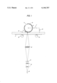
- FIG. 1 represents diagrammatically a typical imaging apparatus for carrying out a photoelectrophoretic migration imaging process using the compounds of the invention.
- G 1 and G 2 represent cyano
- R 1 and R 2 are the same and represent --CH ⁇ CH--A 2 ;
- a 2 represent anthracene-9-yl or 2,3,6,7-tetrahydro-1H,5H-benzo[ij]quinolizin-9-yl and 2-styrylthien-5-yl;
- R 3 and R 4 represent hydrogen.
- X represents O
- G 1 and G 2 represent cyano
- R 1 represents --CH ⁇ A 1 and A 1 represents 2,6-diphenyl-4H-pyran-4-ylidene;
- R 2 represents --CH ⁇ CH--A 2 and A 2 represents anthracen-9-yl or 2,3,6,7-tetrahydro-1H,5H-benzo[ij]quinolizin-9-yl;
- R 3 and R 4 represent hydrogen.
- X represents S
- G 1 and G 2 represent cyano
- R 1 and R 2 are the same and represent --CH ⁇ CH--A 2 ;
- a 2 represents 2,3,6,7-tetrahydro-1H,5H-benzo[ij]-quinolizin-9-yl or 1,2,3,4-tetrahydro-N-methylquinolin-6-yl;
- R 3 and R 4 are hydrogen.
- X represents NR and R is butyl or benzyl
- G 1 and G 2 represent cyano
- R 1 and R 2 are the same and represent --CH ⁇ CH--A 2 ;
- a 2 represents 4-(N,N-dimethylamino)phenyl, 2,3,6,7-tetrahydro-1H,5H-benzo[ij]quinolizin-9-yl or 4-(N,N-diethylamino)-2-methoxyphenyl;
- R 3 and R 4 represent hydrogen.
- G 1 and G 2 are each cyano or together with the carbon atom to which they are attached represent sufficient atoms to form an ethyl substituted barbituric acid nucleus;
- R 1 represents phenyl
- R 2 represents --CH ⁇ CH--CH ⁇ A 1 or --CH ⁇ CH--A 2 ;
- a 1 represents 3-ethylbenzoxazolin-2-ylidene
- a 2 represents 2,3,6,7-tetrahydro-1H,5H-benzo[ij]-quinolizin-9-yl
- R 3 and R 4 represent hydrogen.
- X represents O
- G 1 and G 2 represent cyano
- R 3 together with R 2 and R 1 together with R 4 represent sufficient atoms to form a fused substituted six-membered saturated carbocyclic ring; and said carbocyclic ring substituents are selected from the group consisting of 2,3,6,7-tetrahydro-1H,5H-benzo[ij]quinolizin-9-ylmethylene and 4-(N,N-dimethylamino)-benzylidene.
- the materials of Formula I which have been found to be electrophotosensitive tend to exhibit a maximum absorption wavelength, ⁇ max, within the range of from about 420 to about 750 nm.
- ⁇ max maximum absorption wavelength
- a variety of different materials within the class defined by Formula I have been tested and found to exhibit useful levels of electrical photosensitivity in electrophoretic migration imaging processes.
- the electrically photosensitive compounds described herein are useful in the preparation of the electrically photosensitive imaging particles used in electrophoretic migration imaging processes.
- electrically photosensitive particles useful in such processes have an average particle size within the range of from about 0.01 micron to about 20 microns, preferably from about 0.01 to about 5 microns.
- these particles are composed of one or more colorants such as the colorants described in the present invention.
- these electrically photosensitive particles may also contain various nonphotosensitive materials such as electrically insulating polymers, charging control agents, various organic and inorganic fillers, as well as various additional dyes or pigment materials to change or enhance various colorant and physical properties of the electrically photosensitive particle.
- such electrically photosensitive particles may contain other photosensitive materials such as various sensitizing dyes and/or chemical sensitizers to alter or enhance their response characteristics to activating radiation.
- the electrically photosensitive compounds described in Table I are typically positioned in particulate form, between two or more spaced electrodes, one or both of which typically are transparent to radiation to which the electrically photosensitive material is light-sensitive, i.e., activating radiation.
- the electrically photosensitive material, in particulate form may be dispersed simply as a dry powder between two spaced electrodes and then subjected to a typical electrophoretic migration imaging operation such as that described in U.S. Pat. No.
- the carrier material when the electrically photosensitive particles used in the present invention are dispersed in an electrically insulating carrier material, such carrier material may assume a variety of physical forms and may be selected from a variety of different materials.
- the carrier material may be a matrix of an electrically insulating, normally solid polymeric material capable of being softened or liquefied upon application of heat, solvent, and/or pressure so that the electrically photosensitive particulate material dispersed therein can migrate through the matrix.
- the carrier material can comprise an electrically insulating liquid such as decane, paraffin, Sohio Odorless Solvent 3440 (a kerosene fraction marketed by the Standard Oil Company, Ohio), various isoparaffinic hydrocarbon liquids such as those sold under the trademark Isopar G by Exxon Corporation and having a boiling point in the range of 145° C.
- an electrically insulating liquid such as decane, paraffin, Sohio Odorless Solvent 3440 (a kerosene fraction marketed by the Standard Oil Company, Ohio), various isoparaffinic hydrocarbon liquids such as those sold under the trademark Isopar G by Exxon Corporation and having a boiling point in the range of 145° C.
- various halogenated hydrocarbons such as carbon tetrachloride, trichloromonofluoromethane, and the like
- various alkylated aromatic hydrocarbon liquids such as the alkylated benzenes, for example, xylenes, and other alkylated aromatic hydrocarbons such as are described in U.S. Pat. No. 2,899,335.
- An example of one such useful alkylated aromatic hydrocarbon liquid which is commercially available is Solvesso 100 made by Exxon Corporation. Solvesso 100 has a boiling point in the range of about 157° C. to about 177° C.
- the electrically insulating carrier material used in the present invention is a material having a resistivity greater than about 10 9 ohm-cm, preferably greater than about 10 12 ohm-cm.
- a carrier material such as one of the above-described electrically insulating liquids
- various other addenda may also be incorporated in the resulting imaging suspension.
- charge control agents may be incorporated in such a suspension to improve the uniformity of charge polarity of the electrically photosensitive particles dispersed in the liquid suspension.
- charge control agents are well known in the field of liquid electrographic developer compositions where they are employed for purposes substantially similar to that described herein. Thus, extensive discussion of the materials herein is deemed unnecessary. These materials are typically polymeric materials incorporated by admixture thereof into the liquid carrier vehicle of the suspension. In addition to, and possibly related to, the aforementioned enhancement of uniform charge polarity, it has been found that the charge control agents often provide more stable suspensions, i.e., suspensions which exhibit substantially less settling out of the dispersed photosensitive particles.
- various polymeric binder materials such as various natural, semi-synthetic or synthetic resins, may be dispersed or dissolved in the electrically insulating carrier to serve as a fixing material for the final photosensitive particle image formed on one of the spaced electrodes used in electrophoretic migration imaging systems.
- fixing addenda is conventional and well known in the closely related art of liquid electrographic developer compositions so that extended discussion thereof is unnecessary herein.
- FIG. 1 illustrates a typical apparatus which employs the electrophoretic migration imaging.
- FIG. 1 shows a transparent electrode 1 supported by two rubber drive rollers 10 capable of imparting a translating motion via original image 11 to electrode 1 in the direction of the arrow.
- Electrode 1 may be composed of a layer of optically transparent material, such as glass or an electrically insulating, transparent polymeric support such as polyethylene terephthalate, covered with a thin, optically transparent, conductive layer such as tin oxide, indium oxide, nickel, and the like.
- the surface of electrode 1 may bear a "dark charge exchange" material, such as a solid solution of an electrically insulating polymer and 2,4,7-trinitro-9-fluorenone as described by Groner in U.S. Pat. No. 3,976,485 issued Aug. 24, 1976.
- Electrode 5 is connected to one side of the power source 15 by switch 7. The opposite side of the power source 15 is connected to electrode 1 so that as an exposure takes place, switch 7 is closed and an electric field is applied to the electrically photosensitive particulate material 4 which is positioned between electrodes 1 and 5.
- electrically photosensitive particulate material 4 is dispersed in an electrically insulating carrier material such as described hereinabove.
- the electrically photosensitive particulate material 4 may be positioned between electrodes 1 and 5 by applying material 4 to either or both of the surfaces of electrodes 1 and 5 prior to the imaging process or by injecting electrically photosensitive imaging material 4 between electrodes 1 and 5 during the electrophoretic migration imaging process.
- exposure of electrically photosensitive particulate material 4 takes place by use of an exposure system consisting of light source 8, an original image 11 to be reproduced, such as a photographic transparency, a lens system 12, and any necessary or desirable radiation filters 13, such as color filters, whereby electrically photosensitive material 4 is irradiated with a pattern of activating radiation corresponding to original image 11.
- the electrophoretic migration imaging system represented in FIG. 1 shows electrode 1 to be transparent to activating radiation from light source 8, it is possible to irradiate electrically photosensitive particulate material 4 in the nip 21 between electrodes 1 and 5 without either of electrodes 1 or 5 being transparent.
- the exposure source 8 and lens system 12 is arranged so that image material 4 is exposed in the nip or gap 21 between electrodes 1 and 5.
- electrode 5 is a roller electrode having a conductive core 14 connected to power source 15.
- the core is in turn covered with a layer of insulating material 6, for example, baryta paper.
- Insulating material 6 serves to prevent or at least substantially reduce the capability of electrically photosensitive particulate material 4 to undergo a radiation induced charge alteration upon interaction with electrode 5.
- blocking electrode may be used, as is conventional in the art of electrophoretic migration imaging, to refer to electrode 5.
- electrode 5 is shown as a roller electrode and electrode 1 is shown as essentially a translatable, flat plate electrode in FIG. 1, either or both of these electrodes may assume a variety of different shapes such as a web electrode, rotating drum electrode, plate electrode, and the like as is well known in the field of electrophoretic migration imaging.
- electrodes 1 and 5 are spaced such that they are in pressure contact or very close to one another during the electrophoretic migration imaging process, e.g., less than 50 microns apart.
- electrically photosensitive particulate material 4 is dispersed simply in an air gap between electrodes 1 and 5 or in a carrier such as a layer of heat-softenable or other liquefiable material coated as a separate layer on electrode 1 and/or 5, these electrodes may be spaced more than 50 microns apart during the imaging process.
- the strength of the electric field imposed between electrodes 1 and 5 during the electrophoretic migration imaging process may vary considerably; however, it has generally been found that optimum image density and resolution are obtained by increasing the field strength to as high a level as possible without causing electrical breakdown of the carrier medium in the electrode gap.
- electrically insulating liquids such as isoparaffinic hydrocarbons are used as the carrier in the imaging apparatus of FIG. 1
- the applied voltage across electrodes 1 and 5 typically is within the range of from about 100 volts to about 4 kilovolts or higher.
- image formation occurs in electrophoretic migration imaging processes as the result of the combined action of activating radiation and electric field on the electrically photosensitive particulate material 4 disposed between electrodes 1 and 5 in the attached drawing.
- field application and exposure to activating radiation occurs concurrently.
- process parameters such as field strength, activating radiation intensity, incorporation of suitable light sensitive addenda in or together with the electrically photosensitive particles formed from the material of Formula I, e.g., by incorporation of a persistent photoconductive material, and the like, it is possible to alter the timing of the exposure and field application events so that one may use sequential exposure and field application events rather than concurrent field application and exposure events.
- electrically photosensitive particulate material 4 When disposed between imaging electrodes 1 and 5 of FIG. 1, electrically photosensitive particulate material 4 exhibits an electrostatic charge polarity, either as a result of triboelectric interaction of the particles or as a result of the particles interacting with the carrier material in which they are dispersed, for example, an electrically insulating liquid, such as occurs in conventional liquid electrographic developing compositions composed of toner particles which acquire a charge upon being dispersed in an electrically insulating carrier liquid.
- an electrically insulating liquid such as occurs in conventional liquid electrographic developing compositions composed of toner particles which acquire a charge upon being dispersed in an electrically insulating carrier liquid.
- Image discrimination occurs in the electrophoretic migration imaging process as a result of the combined application of electric field and activating radiation on the electrically photosensitive particulate material dispersed between electrodes 1 and 5 of the apparatus shown in FIG. 1. That is, in a typical imaging operation, upon application of an electric field between electrodes 1 and 5, the particles 4 of charge-bearing, electrically photosensitive material are attracted in the dark to either electrodes 1 or 5, depending upon which of these electrodes has a polarity opposite to that of the original charge polarity acquired by the electrically photosensitive particles. And, upon exposing particles 4 to activating electromagnetic radiation, it is theorized that there occurs neutralization or reversal of the charge polarity associated with either the exposed or unexposed particles.
- Electrode 1 bears a conductive surface
- the exposed, electrically photosensitive particles 4 upon coming into electrical contact with such conductive surface, undergo an alteration (usually a reversal) of their original charge polarity as a result of the combined application of electric field and activating radiation.
- PIER photoimmobilized electrophoretic recording
- the surface of electrode 1 bears a dark charge exchange material as described by Groner in aforementioned U.S. Pat. No. 3,976,485
- the images which are formed on the surface of electrodes 1 and/or 5 of the apparatus shown in FIG. 1 may be temporarily or permanently fixed to these electrodes or may be transferred to a final image receiving element.
- Fixing of the final particle image can be effected by various techniques, for example, by applying a resinous coating over the surface of the image bearing substrate. For example, if electrically photosensitive particles 4 are dispersed in a liquid carrier between electrodes 1 and 5, one may fix the image or images formed on the surface of electrodes 1 and/or 5 by incorporating a polymeric binder material in the carrier liquid.
- binders which are well known for use in liquid electrophotographic liquid developers
- binders are known to acquire a charge polarity upon being admixed in a carrier liquid and therefore will, themselves, electrophoretically migrate to the surface of one or the other of the electrodes.
- a coating of a resinous binder (which has been admixed in the carrier liquid), may be formed on the surfaces of electrodes 1 and/or 5 upon evaporation of the liquid carrier.
- the electrically photosensitive colorant compounds of Formula I may be used to form monochrome images, or the compounds may be admixed with other electrically photosensitive material of proper color and photosensitivity and used to form polychrome images.
- Many of the electrically photosensitive compounds having Formula I have especially useful hues which make them particularly suited for use in polychrome imaging processes which employ a mixture of two or more differently colored electrically photosensitive particles.
- this liquid mixture of particulate material exhibits a black coloration.
- the specific cyan, magenta, and yellow particles selected for use in such a polychrome imaging process are chosen so that their spectral response curves do not appreciably overlap whereby color separation and subtractive multicolor image reproduction can be achieved.
- FIG. 1 An imaging apparatus was used in each of the following examples to carry out the electrophoretic migration imaging process described herein.
- This apparatus was a device of the type illustrated in FIG. 1.
- a translating film base having a conductive coating of 0.1 optical density cermet (Cr.SiO) served as electrode 1 and was in pressure contact with a 10 centimeter diameter aluminum roller 14 covered with dielectric paper coated with poly(vinyl butyral) resin which served as electrode 5.
- Plate 1 was supported by two 2.8 cm. diameter rubber drive rollers 10 positioned beneath film plate 1 such that a 2.5 cm. opening, symmetric with the axis of the aluminum roller 14, existed to allow exposure of electrically photosensitive particles 4 to activating radiation.
- the original transparency 11 to be reproduced was taped to the back side of film plate 1.
- the original transparency to be reproduced consisted of adjacent strips of clear (WO), red (W29), green (W61) and blue (W47B) filters.
- the light source consisted of a Kodak Ektagraphic AV434A Carousel Projector with a 1000 watt Xenon Lamp.
- the light was modulated with a Kodak No. 5 flexible M-carbon eleven step 0.3 neutral density step tablet.
- the residence time in the exposure zone was 10 milliseconds.
- the log of the light intensity (Log I) was as follows:
- the voltage between the electrode 5 and film plate 1 was about 2 kv.
- Film plate 1 was negative polarity in the case where electrically photosensitive particulate material 4 carried a positive electrostatic charge, and film plate 1 was positive in the case where electrically photosensitive electrostatically charged particles were negatively charged.
- the translational speed of film plate 1 was about 25 cm. per second.
- image formation occurs on the surfaces of film plate 1 and electrode 5 after simultaneous application of light exposure and electric field to electrically photosensitive material evaluated for use.
- Electrically photosensitive particulate material 4 was admixed with a liquid carrier as described below to form a liquid imaging dispersion which was placed in nip 21 between the electrodes 1 and 5. If the material being evaluated for use as material 4 possessed a useful level of electrical photosensitivity, one obtained a negative-appearing image reproduction of original 11 on electrode 5 and a complementary image on electrode 1.
- Imaging dispersions were prepared to evaluate each of the compounds in Table I.
- the dispersions were prepared by first making a stock solution of the following components. The stock solution was prepared simply by combining the components.
Abstract
Novel compounds having the following structure ##STR1## wherein X represents O, S or NR and R is benzyl or butyl;
G1 and G2 represent cyano or taken together with the carbon atom to which they are attached represent sufficient atoms to complete an ethyl substituted barbituric acid nucleus;
R1 and R2, which may be the same or different represent phenyl, (--CH═n A1, --CH═CH--A2 ; and R3, R4, A1, A2 and n are as stated in the detailed disclosure.
Description
This is a divisional of U.S. patent application Ser. No. 816,128 filed by Van Allan et al. on July 15, 1977.
This invention relates to electrophoretic migration imaging processes and, in particular, to the use of certain photosensitive pigment materials in such processes.
In the past, there has been extensive description in the patent and other technical literature of electrophoretic migration imaging processes. For example, a description of such processes may be found in U.S. Pat. Nos. 2,758,939 by Sugarman issued Aug. 14, 1956; 2,940,847, 3,100,426, 3,140,175 and 3,143,508, all by Kaprelian; 3,384,565, 3,384,488 and 3,615,558, all by Tulagin et al; 3,384,566 by Clark; and 3,383,993 by Yeh. In addition to the foregoing patent literature directed to conventional photoelectrophoretic migration imaging processes, another type of electrophoretic migration imaging process which advantageously provides for image reversal is described in Groner, U.S. Pat. No. 3,976,485 issued Aug. 24, 1976. This latter process has been termed photoimmobilized electrophoretic recording or PIER.
In general, each of the foregoing electrophoretic migration imaging processes typically employs a layer of electrostatic charge-bearing photoconductive particles, i.e., electrically photosensitive particles, positioned between two spaced electrodes, one of which may be transparent. To achieve image formation in these processes, the charge-bearing photosensitive particles positioned between the two spaced electrodes, as described above, are subjected to the influence of an electric field and exposed to activating radiation. As a result, the charge-bearing electrically photosensitive particles are caused to migrate electrophoretically to the surface of one or the other of the spaced electrodes, and one obtains an image pattern on the surface of these electrodes. Typically, a negative image is formed on one electrode, and a positive image is formed on the opposite electrode. Image discrimination occurs in the various electrophoretic migration imaging processes as a result of a net change in charge polarity of either the exposed electrically photosensitive particles (in the case of conventional electrophoretic migration imaging) or the unexposed electrically photosensitive particles (in the case of the electrophoretic migration imaging process described in the above-noted Groner patent) so that the image formed on one electrode surface is composed ideally of electrically photosensitive particles of one charge polarity, either negative or positive polarity, and the image formed on the opposite polarity electrode surface is composed ideally of electrically photosensitive particles having the opposite charge polarity, either positive or negative respectively.
In any case, regardless of the particular electrophoretic migration imaging process employed, it is apparent that an essential component of any such process is the electrically photosensitive particles. And, of course, to obtain an easy-to-read, visible image it is important that these electrically photosensitive particles be colored, as well as electrically photosensitive. Accordingly, there exists a continuing effort to find particles which possess both useful levels of electrical photosensitivity and which exhibit good colorant properties. Thus, various types of electrically photosensitive materials are disclosed for use in electrophoretic migration imaging processes. See for example U.S. Pat. Nos. 2,758,939 by Sugarman, 2,940,847 by Kaprelian, and 3,384,488 and 3,615,558 by Tulagin et al., noted hereinabove.
Useful electrically photosensitive or photoconductive pigment materials for electrophoretic migration imaging usually have been frequently selected from known classes of photoconductive materials which may be employed in conventional photoconductive elements, e.g., photoconductive plates, drums, or webs used in electrophotographic office-copier devices. For example, both Sugarman and Kaprelian in the above-referenced patents state that electrically photosensitive materials useful in electrophoretic migration imaging processes may be selected from known classes of photoconductive materials. Also, the phthalocyanine pigments described as a useful electrically photosensitive material for electrophoretic imaging processes in U.S. Pat. No. 3,615,558 by Tulagin et al. have long been known to exhibit useful photoconductive properties.
In accord with the present invention, a group of novel compounds have been discovered which are useful in electrophoretic migration imaging processes. To the best of our knowledge, none of said materials have been previously identified as photoconductors. Said compounds have the following structure: ##STR2## wherein
X represents O, S or NR and R is benzyl or butyl;
G1 and G2 represent cyano or taken together with the carbon atom to which they are attached represent sufficient atoms to complete an ethyl substituted barbituric acid nucleus;
R1 and R2, which may be the same or different represent phenyl, (--CH═n A1, --CH═CH--A2 ;
R3 and R4 represent hydrogen or R3 together with R2 or R4 together with R1 represent sufficient atoms to form a fused substituted six membered saturated carbocyclic ring and said carbocyclic ring substituents are selected from the group consisting of 2,3,6,7-tetrahydro-1H,5H-benzo[ij]quinolizin-9-ylmethylene and 4-(N,N-dimethylamino)benzylidene;
A1 represents 3-ethylbenzoxazolin-2-ylidene or 2,6-diphenyl-4H-pyran-4-ylidene;
A2 represents anthracene-9-yl; 2,3,6,7-tetrahydro-1H,5H-benzo[ij]quinolizin-9-yl; 2-styrylthien-5-yl; 1,2,3,4-tetrahydro-1-methylquinolin-6-yl; 4-(N,N-dimethylamino)phenyl and 4-(N,N-diethylamino)-2-methoxyphenyl; and
n represents 1 or 3.
Charge-bearing, electrically photosensitive particles formulated from the compounds of the present invention are positioned between two spaced electrodes. Preferably these particles are contained in an electrically insulating carrier such as an electrically insulating liquid or an electrically insulating, liquefiable matrix material, e.g., a thixotropic or a heat- and/or solvent-softenable material, which is positioned between the spaced electrodes. While so positioned between the spaced electrodes, the photosensitive particles are subjected to an electric field and exposed to a pattern of activating radiation. As a consequence, the charge-bearing, electrically photosensitive particles undergo a radiation-induced variation in their charge polarity and migrate to one or the other of the electrode surfaces to form on at least one of these electrodes an image pattern representing a positive-sense or negative-sense image of the original radiation exposure pattern.
FIG. 1 represents diagrammatically a typical imaging apparatus for carrying out a photoelectrophoretic migration imaging process using the compounds of the invention.
In accordance with one embodiment the present invention there is provided a group of compounds which are useful in photoelectrophoretic migration imaging processes. Said materials have a structure according to general Formula I wherein:
X represents 0;
G1 and G2 represent cyano;
R1 and R2 are the same and represent --CH═CH--A2 ;
A2 represent anthracene-9-yl or 2,3,6,7-tetrahydro-1H,5H-benzo[ij]quinolizin-9-yl and 2-styrylthien-5-yl; and
R3 and R4 represent hydrogen.
In accordance with another embodiment of the present invention there are provided compounds according to general Formula I wherein:
X represents O;
G1 and G2 represent cyano;
R1 represents --CH═A1 and A1 represents 2,6-diphenyl-4H-pyran-4-ylidene;
R2 represents --CH═CH--A2 and A2 represents anthracen-9-yl or 2,3,6,7-tetrahydro-1H,5H-benzo[ij]quinolizin-9-yl; and
R3 and R4 represent hydrogen.
In accordance with another embodiment of the present invention, there are provided compounds according to general Formula I wherein
X represents S;
G1 and G2 represent cyano;
R1 and R2 are the same and represent --CH═CH--A2 ;
A2 represents 2,3,6,7-tetrahydro-1H,5H-benzo[ij]-quinolizin-9-yl or 1,2,3,4-tetrahydro-N-methylquinolin-6-yl; and
R3 and R4 are hydrogen.
In accordance with yet another embodiment of the present invention there are provided compounds according to general Formula I wherein
X represents NR and R is butyl or benzyl;
G1 and G2 represent cyano;
R1 and R2 are the same and represent --CH═CH--A2 ;
A2 represents 4-(N,N-dimethylamino)phenyl, 2,3,6,7-tetrahydro-1H,5H-benzo[ij]quinolizin-9-yl or 4-(N,N-diethylamino)-2-methoxyphenyl; and
R3 and R4 represent hydrogen.
In accordance with yet another embodiment of the present invention there are provided compounds according to general Formula I wherein
X represents 0;
G1 and G2 are each cyano or together with the carbon atom to which they are attached represent sufficient atoms to form an ethyl substituted barbituric acid nucleus;
R1 represents phenyl;
R2 represents --CH═CH--CH═A1 or --CH═CH--A2 ;
A1 represents 3-ethylbenzoxazolin-2-ylidene;
A2 represents 2,3,6,7-tetrahydro-1H,5H-benzo[ij]-quinolizin-9-yl; and
R3 and R4 represent hydrogen.
In accordance with yet another embodiment of the present invention, there are provided compounds according to general Formula I wherein
X represents O;
G1 and G2 represent cyano;
R3 together with R2 and R1 together with R4 represent sufficient atoms to form a fused substituted six-membered saturated carbocyclic ring; and said carbocyclic ring substituents are selected from the group consisting of 2,3,6,7-tetrahydro-1H,5H-benzo[ij]quinolizin-9-ylmethylene and 4-(N,N-dimethylamino)-benzylidene.
In general the materials of Formula I which have been found to be electrophotosensitive tend to exhibit a maximum absorption wavelength, λmax, within the range of from about 420 to about 750 nm. A variety of different materials within the class defined by Formula I have been tested and found to exhibit useful levels of electrical photosensitivity in electrophoretic migration imaging processes.
A partial listing of representative compounds are included herein in Table I.
                                  TABLE I
__________________________________________________________________________
No.                                                    Color
__________________________________________________________________________
    ##STR3##                                           Reddish Brown
2
    ##STR4##                                           Dark Purple
3
    ##STR5##                                           Brown
4
    ##STR6##                                           Reddish Purple
5
    ##STR7##                                           Purple
6
    ##STR8##                                           Purple
7
    ##STR9##                                           Black
8
    ##STR10##                                          Purplish Black
9
    ##STR11##                                          Yellow
 10
    ##STR12##                                          Purple
 11
    ##STR13##                                          Purplish Black
 12
    ##STR14##                                          Red
 13
    ##STR15##                                          Orange
 14
    ##STR16##                                          Yellow
 15
    ##STR17##                                          Orange
__________________________________________________________________________
The materials described by general Formula I may be prepared by the various procedures. The procedures disclosed in U.S. Pat. No. 2,965,486 to Brooker et al., issued Dec. 20, 1960 may be used to prepare any of the compounds falling within the scope of general Formula I.
As indicated hereinabove, the electrically photosensitive compounds described herein are useful in the preparation of the electrically photosensitive imaging particles used in electrophoretic migration imaging processes. In general, electrically photosensitive particles useful in such processes have an average particle size within the range of from about 0.01 micron to about 20 microns, preferably from about 0.01 to about 5 microns. Typically, these particles are composed of one or more colorants such as the colorants described in the present invention. However, these electrically photosensitive particles may also contain various nonphotosensitive materials such as electrically insulating polymers, charging control agents, various organic and inorganic fillers, as well as various additional dyes or pigment materials to change or enhance various colorant and physical properties of the electrically photosensitive particle. In addition, such electrically photosensitive particles may contain other photosensitive materials such as various sensitizing dyes and/or chemical sensitizers to alter or enhance their response characteristics to activating radiation.
When used in an electrophoretic migration imaging process, the electrically photosensitive compounds described in Table I are typically positioned in particulate form, between two or more spaced electrodes, one or both of which typically are transparent to radiation to which the electrically photosensitive material is light-sensitive, i.e., activating radiation. Although the electrically photosensitive material, in particulate form, may be dispersed simply as a dry powder between two spaced electrodes and then subjected to a typical electrophoretic migration imaging operation such as that described in U.S. Pat. No. 2,758,939 by Sugarman, it is more typical to disperse the electrically photosensitive particulate material in an electrically insulating carrier, such as an electrically insulating liquid, or an electrically insulating, liquefiable matrix material, such as a heat- and/or solvent-softenable polymeric material or a thixotropic polymeric material. Typically, when one employs such a dispersion of electrically photosensitive particulate material and electrically insulating carrier material between the spaced electrodes of an electrophoretic migration imaging system, it is conventional to employ from about 0.05 part to about 2.0 parts of electrically photosensitive particulate material for each 10 parts by weight of electrically insulating carrier material.
As indicated above, when the electrically photosensitive particles used in the present invention are dispersed in an electrically insulating carrier material, such carrier material may assume a variety of physical forms and may be selected from a variety of different materials. For example, the carrier material may be a matrix of an electrically insulating, normally solid polymeric material capable of being softened or liquefied upon application of heat, solvent, and/or pressure so that the electrically photosensitive particulate material dispersed therein can migrate through the matrix. In another, more typical embodiment of the invention, the carrier material can comprise an electrically insulating liquid such as decane, paraffin, Sohio Odorless Solvent 3440 (a kerosene fraction marketed by the Standard Oil Company, Ohio), various isoparaffinic hydrocarbon liquids such as those sold under the trademark Isopar G by Exxon Corporation and having a boiling point in the range of 145° C. to 186° C., various halogenated hydrocarbons such as carbon tetrachloride, trichloromonofluoromethane, and the like, various alkylated aromatic hydrocarbon liquids such as the alkylated benzenes, for example, xylenes, and other alkylated aromatic hydrocarbons such as are described in U.S. Pat. No. 2,899,335. An example of one such useful alkylated aromatic hydrocarbon liquid which is commercially available is Solvesso 100 made by Exxon Corporation. Solvesso 100 has a boiling point in the range of about 157° C. to about 177° C. and is composed of 9 percent dialkyl benzenes, 37 percent trialkyl benzenes, and 4 percent aliphatics. Typically, whether solid or liquid at normal room temperatures, i.e., about 22° C., the electrically insulating carrier material used in the present invention is a material having a resistivity greater than about 109 ohm-cm, preferably greater than about 1012 ohm-cm. When the electrically photosensitive particles formed from the materials of the present invention are incorporated in a carrier material, such as one of the above-described electrically insulating liquids, various other addenda may also be incorporated in the resulting imaging suspension. For example, various charge control agents may be incorporated in such a suspension to improve the uniformity of charge polarity of the electrically photosensitive particles dispersed in the liquid suspension. Such charge control agents are well known in the field of liquid electrographic developer compositions where they are employed for purposes substantially similar to that described herein. Thus, extensive discussion of the materials herein is deemed unnecessary. These materials are typically polymeric materials incorporated by admixture thereof into the liquid carrier vehicle of the suspension. In addition to, and possibly related to, the aforementioned enhancement of uniform charge polarity, it has been found that the charge control agents often provide more stable suspensions, i.e., suspensions which exhibit substantially less settling out of the dispersed photosensitive particles.
In addition to the foregoing charge control agent materials, various polymeric binder materials such as various natural, semi-synthetic or synthetic resins, may be dispersed or dissolved in the electrically insulating carrier to serve as a fixing material for the final photosensitive particle image formed on one of the spaced electrodes used in electrophoretic migration imaging systems. Here again, the use of such fixing addenda is conventional and well known in the closely related art of liquid electrographic developer compositions so that extended discussion thereof is unnecessary herein.
The process of the present invention will be described in more detail with reference to the accompanying drawing, FIG. 1, which illustrates a typical apparatus which employs the electrophoretic migration imaging.
FIG. 1 shows a transparent electrode 1 supported by two rubber drive rollers 10 capable of imparting a translating motion via original image 11 to electrode 1 in the direction of the arrow. Electrode 1 may be composed of a layer of optically transparent material, such as glass or an electrically insulating, transparent polymeric support such as polyethylene terephthalate, covered with a thin, optically transparent, conductive layer such as tin oxide, indium oxide, nickel, and the like. Optionally, depending upon the particular type of electrophoretic migration imaging process desired, the surface of electrode 1 may bear a "dark charge exchange" material, such as a solid solution of an electrically insulating polymer and 2,4,7-trinitro-9-fluorenone as described by Groner in U.S. Pat. No. 3,976,485 issued Aug. 24, 1976.
Spaced opposite electrode 1 and in pressure contact therewith is a second electrode 5, an idler roller which serves as a counter electrode to electrode 1 for producing the electric field used in the electrophoretic migration imaging process. Typically, electrode 5 has on the surface thereof a thin, electrically insulating layer 6. Electrode 5 is connected to one side of the power source 15 by switch 7. The opposite side of the power source 15 is connected to electrode 1 so that as an exposure takes place, switch 7 is closed and an electric field is applied to the electrically photosensitive particulate material 4 which is positioned between electrodes 1 and 5. Typically, electrically photosensitive particulate material 4 is dispersed in an electrically insulating carrier material such as described hereinabove.
The electrically photosensitive particulate material 4 may be positioned between electrodes 1 and 5 by applying material 4 to either or both of the surfaces of electrodes 1 and 5 prior to the imaging process or by injecting electrically photosensitive imaging material 4 between electrodes 1 and 5 during the electrophoretic migration imaging process.
As shown in FIG. 1, exposure of electrically photosensitive particulate material 4 takes place by use of an exposure system consisting of light source 8, an original image 11 to be reproduced, such as a photographic transparency, a lens system 12, and any necessary or desirable radiation filters 13, such as color filters, whereby electrically photosensitive material 4 is irradiated with a pattern of activating radiation corresponding to original image 11. Although the electrophoretic migration imaging system represented in FIG. 1 shows electrode 1 to be transparent to activating radiation from light source 8, it is possible to irradiate electrically photosensitive particulate material 4 in the nip 21 between electrodes 1 and 5 without either of electrodes 1 or 5 being transparent. In such a system, although not shown in FIG. 1, the exposure source 8 and lens system 12 is arranged so that image material 4 is exposed in the nip or gap 21 between electrodes 1 and 5.
As shown in FIG. 1, electrode 5 is a roller electrode having a conductive core 14 connected to power source 15. The core is in turn covered with a layer of insulating material 6, for example, baryta paper. Insulating material 6 serves to prevent or at least substantially reduce the capability of electrically photosensitive particulate material 4 to undergo a radiation induced charge alteration upon interaction with electrode 5. Hence, the term "blocking electrode" may be used, as is conventional in the art of electrophoretic migration imaging, to refer to electrode 5.
Although electrode 5 is shown as a roller electrode and electrode 1 is shown as essentially a translatable, flat plate electrode in FIG. 1, either or both of these electrodes may assume a variety of different shapes such as a web electrode, rotating drum electrode, plate electrode, and the like as is well known in the field of electrophoretic migration imaging. In general, during a typical electrophoretic migration imaging process wherein electrically photosensitive material 4 is dispersed in an electrically insulating, liquid carrier, electrodes 1 and 5 are spaced such that they are in pressure contact or very close to one another during the electrophoretic migration imaging process, e.g., less than 50 microns apart. However, where electrically photosensitive particulate material 4 is dispersed simply in an air gap between electrodes 1 and 5 or in a carrier such as a layer of heat-softenable or other liquefiable material coated as a separate layer on electrode 1 and/or 5, these electrodes may be spaced more than 50 microns apart during the imaging process.
The strength of the electric field imposed between electrodes 1 and 5 during the electrophoretic migration imaging process may vary considerably; however, it has generally been found that optimum image density and resolution are obtained by increasing the field strength to as high a level as possible without causing electrical breakdown of the carrier medium in the electrode gap. For example, when electrically insulating liquids such as isoparaffinic hydrocarbons are used as the carrier in the imaging apparatus of FIG. 1, the applied voltage across electrodes 1 and 5 typically is within the range of from about 100 volts to about 4 kilovolts or higher.
As explained hereinabove, image formation occurs in electrophoretic migration imaging processes as the result of the combined action of activating radiation and electric field on the electrically photosensitive particulate material 4 disposed between electrodes 1 and 5 in the attached drawing. Typically, for best results, field application and exposure to activating radiation occurs concurrently. However, as would be expected, by appropriate selection of various process parameters such as field strength, activating radiation intensity, incorporation of suitable light sensitive addenda in or together with the electrically photosensitive particles formed from the material of Formula I, e.g., by incorporation of a persistent photoconductive material, and the like, it is possible to alter the timing of the exposure and field application events so that one may use sequential exposure and field application events rather than concurrent field application and exposure events.
When disposed between imaging electrodes 1 and 5 of FIG. 1, electrically photosensitive particulate material 4 exhibits an electrostatic charge polarity, either as a result of triboelectric interaction of the particles or as a result of the particles interacting with the carrier material in which they are dispersed, for example, an electrically insulating liquid, such as occurs in conventional liquid electrographic developing compositions composed of toner particles which acquire a charge upon being dispersed in an electrically insulating carrier liquid.
Image discrimination occurs in the electrophoretic migration imaging process as a result of the combined application of electric field and activating radiation on the electrically photosensitive particulate material dispersed between electrodes 1 and 5 of the apparatus shown in FIG. 1. That is, in a typical imaging operation, upon application of an electric field between electrodes 1 and 5, the particles 4 of charge-bearing, electrically photosensitive material are attracted in the dark to either electrodes 1 or 5, depending upon which of these electrodes has a polarity opposite to that of the original charge polarity acquired by the electrically photosensitive particles. And, upon exposing particles 4 to activating electromagnetic radiation, it is theorized that there occurs neutralization or reversal of the charge polarity associated with either the exposed or unexposed particles. In typical electrophoretic migration imaging systems wherein electrode 1 bears a conductive surface, the exposed, electrically photosensitive particles 4, upon coming into electrical contact with such conductive surface, undergo an alteration (usually a reversal) of their original charge polarity as a result of the combined application of electric field and activating radiation. Alternatively, in the case of photoimmobilized electrophoretic recording (PIER), wherein the surface of electrode 1 bears a dark charge exchange material as described by Groner in aforementioned U.S. Pat. No. 3,976,485, one obtains reversal of the charge polarity of the unexposed particles, while maintaining the original charge polarity of the exposed electrically photosensitive particles, as these particles come into electrical contact with the dark charge exchange surface of electrode 1. In any case, upon the application of electric field and activating radiation to electrically photosensitive particulate material 4 disposed between electrodes 1 and 5 of the apparatus shown in FIG. 1, one can effectively obtain image discrimination so that an image pattern is formed by the electrically photosensitive particles which corresponds to the original pattern of activating radiation. Typically, using the apparatus shown in FIG. 1, one obtains a visible image on the surface of electrode 1 and a complementary image pattern on the surface of electrode 5.
Subsequent to the application of the electric field and exposure to activating radiation, the images which are formed on the surface of electrodes 1 and/or 5 of the apparatus shown in FIG. 1 may be temporarily or permanently fixed to these electrodes or may be transferred to a final image receiving element. Fixing of the final particle image can be effected by various techniques, for example, by applying a resinous coating over the surface of the image bearing substrate. For example, if electrically photosensitive particles 4 are dispersed in a liquid carrier between electrodes 1 and 5, one may fix the image or images formed on the surface of electrodes 1 and/or 5 by incorporating a polymeric binder material in the carrier liquid. Many such binders (which are well known for use in liquid electrophotographic liquid developers) are known to acquire a charge polarity upon being admixed in a carrier liquid and therefore will, themselves, electrophoretically migrate to the surface of one or the other of the electrodes. Alternatively, a coating of a resinous binder (which has been admixed in the carrier liquid), may be formed on the surfaces of electrodes 1 and/or 5 upon evaporation of the liquid carrier.
The electrically photosensitive colorant compounds of Formula I may be used to form monochrome images, or the compounds may be admixed with other electrically photosensitive material of proper color and photosensitivity and used to form polychrome images. Many of the electrically photosensitive compounds having Formula I have especially useful hues which make them particularly suited for use in polychrome imaging processes which employ a mixture of two or more differently colored electrically photosensitive particles. When such a mixture of multicolored electrically photosensitive particles is formed, for example, in an electrically insulating carrier liquid, this liquid mixture of particulate material exhibits a black coloration. Preferably, the specific cyan, magenta, and yellow particles selected for use in such a polychrome imaging process are chosen so that their spectral response curves do not appreciably overlap whereby color separation and subtractive multicolor image reproduction can be achieved.
The following examples illustrate the utility of the Formula I materials in electrophoretic migration imaging processes.
Imaging Apparatus
An imaging apparatus was used in each of the following examples to carry out the electrophoretic migration imaging process described herein. This apparatus was a device of the type illustrated in FIG. 1. In this apparatus, a translating film base having a conductive coating of 0.1 optical density cermet (Cr.SiO) served as electrode 1 and was in pressure contact with a 10 centimeter diameter aluminum roller 14 covered with dielectric paper coated with poly(vinyl butyral) resin which served as electrode 5. Plate 1 was supported by two 2.8 cm. diameter rubber drive rollers 10 positioned beneath film plate 1 such that a 2.5 cm. opening, symmetric with the axis of the aluminum roller 14, existed to allow exposure of electrically photosensitive particles 4 to activating radiation. The original transparency 11 to be reproduced was taped to the back side of film plate 1.
The original transparency to be reproduced consisted of adjacent strips of clear (WO), red (W29), green (W61) and blue (W47B) filters. The light source consisted of a Kodak Ektagraphic AV434A Carousel Projector with a 1000 watt Xenon Lamp. The light was modulated with a Kodak No. 5 flexible M-carbon eleven step 0.3 neutral density step tablet. The residence time in the exposure zone was 10 milliseconds. The log of the light intensity (Log I) was as follows:
______________________________________
                     Log I
         Filters     erg/cm.sup.2 /sec.
______________________________________
WO         Clear         5.34
W29        Red           4.18
W61        Green         4.17
W47B       Blue          4.15
______________________________________
The voltage between the electrode 5 and film plate 1 was about 2 kv. Film plate 1 was negative polarity in the case where electrically photosensitive particulate material 4 carried a positive electrostatic charge, and film plate 1 was positive in the case where electrically photosensitive electrostatically charged particles were negatively charged. The translational speed of film plate 1 was about 25 cm. per second. In the following examples, image formation occurs on the surfaces of film plate 1 and electrode 5 after simultaneous application of light exposure and electric field to electrically photosensitive material evaluated for use. Electrically photosensitive particulate material 4 was admixed with a liquid carrier as described below to form a liquid imaging dispersion which was placed in nip 21 between the electrodes 1 and 5. If the material being evaluated for use as material 4 possessed a useful level of electrical photosensitivity, one obtained a negative-appearing image reproduction of original 11 on electrode 5 and a complementary image on electrode 1.
Imaging Dispersion Preparation
Imaging dispersions were prepared to evaluate each of the compounds in Table I. The dispersions were prepared by first making a stock solution of the following components. The stock solution was prepared simply by combining the components.
______________________________________
       Isopar G        2.2 g
       Solvesso        1.3 g
       Piccotex 100    1.4 g
       PVT*            0.1 g
______________________________________
 *Poly(vinyltoluene-co-lauryl methacrylate-co-lithium
 methacylate-co-methacrylic acid 56/40/3.6/0.4
A 5 g. aliquot of the stock solution was combined in a closed container with 0.045 g. of the Table I material to be tested and 12 g. of Hamber 440 stainless steel balls. The preparation was then milled for three hours on a paint shaker.
Each of the 15 materials described in Table I was tested according to the just outlined procedure. Each of such compounds was found to be electrophotosensitive as evidenced by obtaining a negative appearing image of the original on one electrode and a complementary image on the other electrode.
The invention has been described in detail with particular reference to certain preferred embodiments thereof, but it will be understood that variations and modifications can be effected within the spirit and scope of the invention.
Claims (8)
1. A compound having the structure: ##STR18## wherein X represents O, S or NR and R is benzyl or butyl;
G1 and G2 represent cyano or taken together with the carbon atom to which they are attached represent sufficient atoms to complete an ethyl substituted barbituric acid nucleus;
R1 and R2 which may be the same or different represent (--CH═n A1 or --CH═CH--A2 wherein at least one of R1 and R2 must be (CH) A1 or --CH═ CH--A2 ;
R3 and R4 represent hydrogen or R3 together with R2 or R4 together with R1 represent sufficient atoms to form a fused substituted six-membered saturated carbocyclic ring and said carbocyclic ring substituents are selected from the group consisting of 2,3,6,7-tetrahydro-1H,5H-benzo[ij]quinolizin-9-ylmethylene and 4-(N,N-dimethylamino)benzylidene;
A1 represents 3-ethylbenzoxazolin-2-ylidene or 2,6-diphenyl-4H-pyran-4-ylidene;
A2 represents anthracene-9-yl; 2,3,6,7-tetrahydro-1H,5H-benzo[ij]quinolizin-9-yl; 2-styrylthiophen-5-yl; 1,2,3,4-tetrahydro-1-methylquinolin-6-yl; 4-(N,N-dimethylamino)phenyl and 4-(N-diethylamino)-2-methoxyphenyl; and
n represents 1 or 3.
2. A compound according to claim 1 wherein
X represents O;
G1 and G2 represent cyano;
R1 and R2 are the same and represent --CH═CH--A2 ;
A2 represents anthracene-9-yl; 2,3,6,7-tetrahydro-1H,5H-benzo[ij]quinolizin-9-yl or 2-styrylthien-5-yl;
R3 and R4 represent hydrogen.
3. A compound according to claim 1 wherein
X represents O;
G1 and G2 represent cyano;
R1 represents --CH═A1 and A1 represents 2,6-diphenyl-4H-pyran-4-ylidene;
R2 represents anthracene-9-yl or 2,3,6,7-tetrahydro-1H,5H-benzo[ij]quinolizin-9-yl; and
R3 and R4 represent hydrogen.
4. A compound according to claim 1 wherein
X represents S;
G1 and G2 represent cyano;
R1 and R2 are the same and represent --CH═CH--A2 ;
A2 represents 2,3,6,7-tetrahydro-1H,5H-benzo[ij]-quinolizin-9-yl or 1,2,3,4-tetrahydro-N-methylquinolin-6-yl; and
R3 and R4 are hydrogen.
5. A compound according to claim 1 wherein
X represents NR and R is butyl or benzyl;
G1 and G2 represent cyano;
R1 and R2 are the same and represent --CH═CH--A2 ;
A2 represents 4-(N,N-dimethylamino)phenyl, 2,3,6,7-tetrahydro-1H,5H-benzo[ij]quinolizin-9-yl or 4-(N,N-diethylamino)-2-methoxyphenyl; and
R3 and R4 represent hydrogen.
6. A compound according to claim 1 wherein
X represents O;
G1 and G2 are each cyano or together with the carbon atom to which they are attached represent sufficient atoms to form an ethyl substituted barbituric acid nucleus;
R1 represents phenyl;
R2 represents --CH═CH--CH═A1 or --CH═CH--A2 ;
A1 represents 3-ethylbenzoxazolin-2-ylidene;
A2 represents 2,3,6,7-tetrahydro-1H,5H-benzo[ij]-quinolizin-9-yl; and
R3 and R4 represent hydrogen.
7. A compound according to claim 1 wherein
X represents O;
G1 and G2 represent cyano;
R3 together with R2 and R1 together with R4 represent sufficient atoms to form a fused substituted six membered saturated carbocyclic ring and said carbocyclic ring substituents are selected from the group consisting of 2,3,6,7-tetrahydro-1H,5H-benzo[ij]-quinolizin-9-ylmethylene and 4-(N,N-dimethylamino)benzylidene.
8. A compound having one of the following structure: ##STR19##
Applications Claiming Priority (1)
| Application Number | Priority Date | Filing Date | Title |
|---|---|---|---|
| US05/816,128 US4145215A (en) | 1977-07-15 | 1977-07-15 | Migration imaging process and compositions |
Related Parent Applications (1)
| Application Number | Title | Priority Date | Filing Date |
|---|---|---|---|
| US05/816,128 Division US4145215A (en) | 1977-07-15 | 1977-07-15 | Migration imaging process and compositions |
Publications (1)
| Publication Number | Publication Date |
|---|---|
| US4146707A true US4146707A (en) | 1979-03-27 |
Family
ID=25219760
Family Applications (2)
| Application Number | Title | Priority Date | Filing Date |
|---|---|---|---|
| US05/816,128 Expired - Lifetime US4145215A (en) | 1977-07-15 | 1977-07-15 | Migration imaging process and compositions |
| US05/874,078 Expired - Lifetime US4146707A (en) | 1977-07-15 | 1978-02-01 | Heterocyclic ethenyl or vinyl heterocyclic or aromatic compounds for migration imaging processes |
Family Applications Before (1)
| Application Number | Title | Priority Date | Filing Date |
|---|---|---|---|
| US05/816,128 Expired - Lifetime US4145215A (en) | 1977-07-15 | 1977-07-15 | Migration imaging process and compositions |
Country Status (6)
| Country | Link |
|---|---|
| US (2) | US4145215A (en) |
| JP (1) | JPS5421722A (en) |
| CA (1) | CA1110898A (en) |
| DE (1) | DE2831054C3 (en) |
| FR (1) | FR2397659A1 (en) |
| GB (1) | GB2002528B (en) |
Cited By (8)
| Publication number | Priority date | Publication date | Assignee | Title |
|---|---|---|---|---|
| US4341894A (en) * | 1978-03-13 | 1982-07-27 | Eastman Kodak Company | Sensitizers for photoconductive compositions |
| US5371228A (en) * | 1989-05-31 | 1994-12-06 | Agfa-Gevaert, N.V. | Dyes and dye-donor elements for use in thermal dye sublimation transfer |
| US5492942A (en) * | 1993-05-25 | 1996-02-20 | Canon Kabushiki Kaisha | Pyran derivative, photosensitive resin composition, and hologram recording medium using it |
| US20050048315A1 (en) * | 2003-08-29 | 2005-03-03 | Semiconductor Energy Laboratory Co., Ltd. | Pyran derivative, method for manufacturing the same, and light-emitting element containing the pyran derivative |
| US6869696B2 (en) * | 2002-05-10 | 2005-03-22 | Sensient Imaging Technologies Gmbh | Organic red electro-luminescent device including a heterocyclic emitter |
| US20050089718A1 (en) * | 2003-10-27 | 2005-04-28 | Semiconductor Energy Laboratory Co., Ltd. | Pyran derivative |
| CN104311477A (en) * | 2014-09-29 | 2015-01-28 | 华东理工大学 | Nitrogen-containing heterocyclic ring compound and application thereof |
| CN104311477B (en) * | 2014-09-29 | 2017-01-04 | 华东理工大学 | Nitrogen-containing heterocyclic compound and use thereof |
Families Citing this family (20)
| Publication number | Priority date | Publication date | Assignee | Title |
|---|---|---|---|---|
| JPS58109483A (en) * | 1981-12-23 | 1983-06-29 | Fuji Photo Film Co Ltd | Compound containing barbituric acid or thiobarbituric acid residue, photoconductive composition and sensitized material for electrophotography containing it |
| DE3506436A1 (en) * | 1985-02-23 | 1986-08-28 | Hoechst Ag, 6230 Frankfurt | NEW STYRENE DERIVATIVES CONTAINING SULPHON, METHOD FOR THE PRODUCTION AND USE THEREOF |
| US5414791A (en) * | 1993-10-05 | 1995-05-09 | Lockheed Missiles & Space Company, Inc. | Thermally stable electro-optic device and method |
| US5561733A (en) * | 1993-10-05 | 1996-10-01 | Lockhead Missiles & Space Company, Inc. | Thermally stable electro-optic device and method |
| US5908581A (en) * | 1997-04-07 | 1999-06-01 | Eastman Kodak Company | Red organic electroluminescent materials |
| US6458474B1 (en) | 1998-03-24 | 2002-10-01 | Fuji Photo Film Co., Ltd. | Methine compound, material for organic luminescence element, organic luminescence element using the same |
| KR100252976B1 (en) * | 1998-04-30 | 2000-08-01 | 구자홍 | Compound for red light emitting device, method thereof, and organic electroluminescent device using the same |
| US6051722A (en) * | 1998-07-06 | 2000-04-18 | Hitachi Chemical Company, Ltd. | Compounds, polymers, resin compositions and nonlinear optical devices |
| JP4652516B2 (en) * | 1999-03-09 | 2011-03-16 | 株式会社林原生物化学研究所 | Pyran derivatives |
| JP4586259B2 (en) * | 2000-11-13 | 2010-11-24 | コニカミノルタホールディングス株式会社 | Red organic electroluminescence device |
| KR100399046B1 (en) * | 2000-12-30 | 2003-09-26 | 한국전자통신연구원 | Organic electro-luminescent device and the preparation thereof |
| DE10109465A1 (en) * | 2001-02-27 | 2002-09-05 | Syntec Ges Fuer Chemie Und Tec | Organic red electroluminescent device |
| US6844089B2 (en) * | 2002-05-10 | 2005-01-18 | Sensient Imaging Technologies Gmbh | Organic red electro-luminescent device and dopant |
| KR100467313B1 (en) * | 2001-11-22 | 2005-01-24 | 한국전자통신연구원 | Red organic electroluminescent compounds, method for synthesizing the same and electroluminescent devices |
| NZ526561A (en) * | 2003-06-18 | 2005-12-23 | Ind Res Ltd | Zwitterionic non-linear optophores and devices incorporating these |
| WO2006132030A1 (en) * | 2005-06-08 | 2006-12-14 | National Institute Of Advanced Industrial Science And Technology | Novel compound, reagent comprising the compound for peptide or protein analysis, and method of analysis with the analytical reagent |
| JP5205085B2 (en) * | 2008-03-12 | 2013-06-05 | 富士フイルム株式会社 | Organic photoelectric conversion material and organic thin film photoelectric conversion element |
| JP5182809B2 (en) * | 2008-07-07 | 2013-04-17 | 独立行政法人産業技術総合研究所 | Protein analysis method and reagent |
| CN104356055B (en) * | 2014-11-04 | 2016-09-28 | 温州大学 | A kind of dihydrogen pyridine derivatives and synthetic method thereof and purposes |
| CN108410203B (en) * | 2018-03-21 | 2020-08-07 | 华东理工大学 | Fluorescent dye based on aggregation-induced emission near infrared, large Stokes shift and photostability as well as preparation method and application thereof |
Citations (2)
| Publication number | Priority date | Publication date | Assignee | Title |
|---|---|---|---|---|
| DE2617345A1 (en) * | 1975-04-21 | 1976-11-04 | Fuji Photo Film Co Ltd | PROCESS FOR MANUFACTURING NEW CONDENSATION PRODUCTS |
| US4012376A (en) * | 1975-12-29 | 1977-03-15 | Eastman Kodak Company | Photosensitive colorant materials |
Family Cites Families (8)
| Publication number | Priority date | Publication date | Assignee | Title |
|---|---|---|---|---|
| LU49058A1 (en) * | 1964-07-23 | 1965-09-13 | ||
| US3442781A (en) * | 1966-01-06 | 1969-05-06 | Xerox Corp | Photoelectrophoretic and xerographic imaging processes employing triphenodioxazines as the electrically photosensitive component |
| US3485633A (en) * | 1966-06-27 | 1969-12-23 | Xerox Corp | Electrophoretic imaging process employing metallic lakes of fluorescein derivatives as the electrically photosensitive material |
| US3546085A (en) * | 1967-01-30 | 1970-12-08 | Xerox Corp | Photoelectrophoretic imaging process and suspension |
| US3574182A (en) * | 1967-02-01 | 1971-04-06 | Xerox Corp | Calcium salt of 6-bromo-1-(1'-sulfo-2'-naphthylazo)-2-naphthol |
| DE1947333A1 (en) * | 1968-09-23 | 1970-03-26 | Xerox Corp | Electrophoretic imaging process |
| CH572233A5 (en) * | 1971-12-28 | 1976-01-30 | Ciba Geigy Ag | |
| US3849132A (en) * | 1973-01-04 | 1974-11-19 | Xerox Corp | Photoelectrophoretic imaging method employing a chromogenic reaction |
-
1977
- 1977-07-15 US US05/816,128 patent/US4145215A/en not_active Expired - Lifetime
-
1978
- 1978-02-01 US US05/874,078 patent/US4146707A/en not_active Expired - Lifetime
- 1978-06-12 CA CA305,192A patent/CA1110898A/en not_active Expired
- 1978-07-12 FR FR7820765A patent/FR2397659A1/en active Granted
- 1978-07-14 JP JP8524378A patent/JPS5421722A/en active Pending
- 1978-07-14 DE DE2831054A patent/DE2831054C3/en not_active Expired
- 1978-07-17 GB GB7830093A patent/GB2002528B/en not_active Expired
Patent Citations (2)
| Publication number | Priority date | Publication date | Assignee | Title |
|---|---|---|---|---|
| DE2617345A1 (en) * | 1975-04-21 | 1976-11-04 | Fuji Photo Film Co Ltd | PROCESS FOR MANUFACTURING NEW CONDENSATION PRODUCTS |
| US4012376A (en) * | 1975-12-29 | 1977-03-15 | Eastman Kodak Company | Photosensitive colorant materials |
Cited By (14)
| Publication number | Priority date | Publication date | Assignee | Title |
|---|---|---|---|---|
| US4341894A (en) * | 1978-03-13 | 1982-07-27 | Eastman Kodak Company | Sensitizers for photoconductive compositions |
| US5371228A (en) * | 1989-05-31 | 1994-12-06 | Agfa-Gevaert, N.V. | Dyes and dye-donor elements for use in thermal dye sublimation transfer |
| US5492942A (en) * | 1993-05-25 | 1996-02-20 | Canon Kabushiki Kaisha | Pyran derivative, photosensitive resin composition, and hologram recording medium using it |
| US5723633A (en) * | 1993-05-25 | 1998-03-03 | Canon Kabushiki Kaisha | Pyran derivative, photosensitive resin composition, and hologram recording medium using it |
| US6869696B2 (en) * | 2002-05-10 | 2005-03-22 | Sensient Imaging Technologies Gmbh | Organic red electro-luminescent device including a heterocyclic emitter |
| US7364804B2 (en) | 2003-08-29 | 2008-04-29 | Semiconductor Energy Laboratory Co., Ltd. | Pyran derivative, method for manufacturing the same, and light-emitting element containing the pyran derivative |
| US20050048315A1 (en) * | 2003-08-29 | 2005-03-03 | Semiconductor Energy Laboratory Co., Ltd. | Pyran derivative, method for manufacturing the same, and light-emitting element containing the pyran derivative |
| US20050089718A1 (en) * | 2003-10-27 | 2005-04-28 | Semiconductor Energy Laboratory Co., Ltd. | Pyran derivative |
| US7217465B2 (en) * | 2003-10-27 | 2007-05-15 | Semicondutor Energy Laboratory Co., Ltd. | Pyran derivative |
| US20070184304A1 (en) * | 2003-10-27 | 2007-08-09 | Semiconductor Energy Laboratory Co., Ltd. | Pyran derivative |
| US7371470B2 (en) | 2003-10-27 | 2008-05-13 | Semiconductor Energy Laboratory Co., Ltd. | Pyran derivative |
| CN100430393C (en) * | 2003-10-27 | 2008-11-05 | 株式会社半导体能源研究所 | Pyran derivative |
| CN104311477A (en) * | 2014-09-29 | 2015-01-28 | 华东理工大学 | Nitrogen-containing heterocyclic ring compound and application thereof |
| CN104311477B (en) * | 2014-09-29 | 2017-01-04 | 华东理工大学 | Nitrogen-containing heterocyclic compound and use thereof |
Also Published As
| Publication number | Publication date |
|---|---|
| JPS5421722A (en) | 1979-02-19 |
| DE2831054B2 (en) | 1982-01-07 |
| FR2397659B1 (en) | 1980-04-04 |
| GB2002528A (en) | 1979-02-21 |
| DE2831054A1 (en) | 1979-01-18 |
| GB2002528B (en) | 1982-01-27 |
| US4145215A (en) | 1979-03-20 |
| DE2831054C3 (en) | 1982-08-12 |
| CA1110898A (en) | 1981-10-20 |
| FR2397659A1 (en) | 1979-02-09 |
Similar Documents
| Publication | Publication Date | Title |
|---|---|---|
| US4146707A (en) | Heterocyclic ethenyl or vinyl heterocyclic or aromatic compounds for migration imaging processes | |
| US4012376A (en) | Photosensitive colorant materials | |
| US3442781A (en) | Photoelectrophoretic and xerographic imaging processes employing triphenodioxazines as the electrically photosensitive component | |
| US4175956A (en) | Electrophotosensitive materials for migration imaging processes | |
| EP0024169A2 (en) | Electrically photosensitive particles for electrophoretic migration imaging processes, dispersions of these particles, and processes using such dispersions | |
| US4197120A (en) | Electrophoretic migration imaging process | |
| US4191566A (en) | Electrophotographic imaging process using anthraquinoid black pigments or metal complexes | |
| US3447922A (en) | Electrically photosensitive particles useful in photoelectrophoretic and xerographic imaging processes | |
| US4282354A (en) | Electrophoretic migration imaging process | |
| US4331751A (en) | Electrically photosensitive materials and elements for photoelectrophoretic imaging processes | |
| US4142890A (en) | Photosensitive trans-epindolidione pigment for migration imaging processes | |
| US3912505A (en) | Color imaging method employing a monolayer of beads | |
| US4241157A (en) | Organic heterocyclic electrophotosensitive materials for migration imaging processes | |
| US4304908A (en) | Methine colorant materials and the use thereof in electrophoretic migration imaging layers and processes | |
| US3676313A (en) | Removing undesired potential from the blocking electrode in a photoelectrophoretic imaging system | |
| US4258112A (en) | Sensitizer for electrophoretic migration imaging dispersions | |
| US4219614A (en) | Electrophoretic migration imaging composition and process using same | |
| US4047944A (en) | Electrophoretic migration imaging process with neutral density bisazo pigments | |
| US4165984A (en) | Electrophoretic migration imaging process | |
| US3448030A (en) | Electrically photosensitive particles useful in photoelectrophoretic and xerographic imaging processes | |
| US4255506A (en) | Electrophoretic migration imaging dispersion | |
| US4251609A (en) | Isoquinolinedione photoelectrophoretic materials for imaging processes | |
| US4166740A (en) | Electrophotosensitive materials for migration imaging processes | |
| CA1079109A (en) | Electrophoretic imaging process in which an electrically photosensitive colorant is subjected to an applied field | |
| USRE30235E (en) | Photosensitive colorant materials |