US4137951A - Apparatus for controlling actuating mechanism of loom dobby - Google Patents
Apparatus for controlling actuating mechanism of loom dobby Download PDFInfo
- Publication number
- US4137951A US4137951A US05/780,188 US78018877A US4137951A US 4137951 A US4137951 A US 4137951A US 78018877 A US78018877 A US 78018877A US 4137951 A US4137951 A US 4137951A
- Authority
- US
- United States
- Prior art keywords
- logic
- indicating
- movement
- program
- logic means
- Prior art date
- Legal status (The legal status is an assumption and is not a legal conclusion. Google has not performed a legal analysis and makes no representation as to the accuracy of the status listed.)
- Expired - Lifetime
Links
- 230000007246 mechanism Effects 0.000 title claims abstract description 36
- 230000033001 locomotion Effects 0.000 claims description 25
- 230000005540 biological transmission Effects 0.000 claims description 4
- 230000008878 coupling Effects 0.000 abstract description 20
- 238000010168 coupling process Methods 0.000 abstract description 20
- 238000005859 coupling reaction Methods 0.000 abstract description 20
- 230000008859 change Effects 0.000 description 13
- 230000009471 action Effects 0.000 description 5
- 230000000994 depressogenic effect Effects 0.000 description 3
- 238000010586 diagram Methods 0.000 description 1
- 238000006073 displacement reaction Methods 0.000 description 1
- 239000004744 fabric Substances 0.000 description 1
- 238000004519 manufacturing process Methods 0.000 description 1
- 238000000034 method Methods 0.000 description 1
- 230000008569 process Effects 0.000 description 1
- 230000000717 retained effect Effects 0.000 description 1
Images


Classifications
-
- D—TEXTILES; PAPER
- D03—WEAVING
- D03C—SHEDDING MECHANISMS; PATTERN CARDS OR CHAINS; PUNCHING OF CARDS; DESIGNING PATTERNS
- D03C1/00—Dobbies
Definitions
- the present invention relates to looms and, more particularly, to apparatus for controlling the actuating mechanism of a dobby employed thereon.
- the present invention can most effectively be used on looms wherein the heald shafts are raised and lowered by means of continuously-rotating dobbies.
- the program carrier contains only information on a change in the state of the actuating mechanism which, via the logical element, is connected to the programming device and kinematically associated with the heald shaft of the loom.
- Used as the actuating mechanism is a changeover clutch with rotary keys.
- the dobby and, consequently, the actuating mechanism that is the changeover clutch
- the heald shaft coupled with the clutch may rise or fall, thus assuming the upper or the lower position.
- Another object of the present invention is to provide an apparatus for controlling the actuating mechanism of a loom dobby, which will be convenient in servicing and reliable in operation.
- Still another object of the invention is to provide an apparatus for controlling the actuating mechanism of a loom dobby, which will enhance the quality of the produced cloth.
- an apparatus for controlling the actuating mechanism of a loom dobby including a programming device with a program carrier containing information on a change in the state of the actuating mechanism coupled with the heald shaft and, at the same time, with the programming device via a logical element
- a unit for comparing the actual position of the heald shaft with the preset one one input of which unit is connected to the program carrier and fed with information on the preset position of the heald shaft, and the other input is connected to the output of the actuating mechanism, thereby establishing a feedback coupling, and fed with information on the actual position of the heald shaft, whereas the output of the comparison unit is connected, via a time-delay element, to the second input of the logical element whose output is directly connected to the actuating mechanism.
- the presence of the comparison unit and the feedback coupling between this unit and the actuating mechanism makes it possible to compare the actual position of the heald shaft with the preset one.
- the result of comparison is transferred, via the time-delay element, to the logical element which, when operating, causes the actuating mechanism and, consequently, the heald shaft to assume a position corresponding to the preset one. Said operations are performed automatically, which adds to the convenience in loom servicing and increases its efficiency.
- the program carrier in the programming device is adapted to move longitudinally, upon a change in information, and in a direction towards readout needles which are installed in the immediate vicinity to this program carrier, a control needle being provided to read out information from the program carrier on the preset position of the heald shaft, and a changeover needle reading out, from the program carrier, information on a change in the state of the actuating mechanism, each needle being secured in an individual needle holder which is stationary on a respective shaft, either on the control shaft or on the changeover one.
- the comparison unit in a preferred embodiment, it is made as a fork and a spring-loaded bush with a flange, installed separately on the control shaft so as to be axially movable, the bush being also mounted on the shaft so as to be relatively rotatable andits flange being provided, along the perimeter, with holes for the tines of the fork to automatically pass therethrough whenever the actual positon of the heald shaft is matched with the preset one, the tines thrusting against the flange as soon as the actual position of the heald shaft becomes different from the preset one, thereby causing the bush with the flange to move in the axial direction.
- the comparison unit includes a crank-arm rigidly installed on the same shaft, kinematically associated with the fork and turning together with the shaft in accordance with the position of the control needle.
- the time-delay element represents a latch thrusting against the bush with the flange as soon as there appears a discrepancy between the actual position of the heald shaft and the preset one, thereby fixing said bush with the flange in an axially displaced position.
- the logical element in the proposed apparatus be made as a bush carrying stops on the outer surface, arranged in a staggered manner, this bush being installed on that of the comparison unit coaxially therewith and adapted to move in the axial direction together with and to turn around this bush, the bush of the logical element being also provided with a pin-and-slot transmission kinematically associated with the crank-arm stationary on the changeover shaft of the programming device turning the logical element depending on the position of the changeover needle.
- the feedback coupling is a leverage connecting the flange of the bush of the comparison unit to the element of the actuating mechanism determining the actual position of the heald shaft.
- FIG. 1 is a block diagram of an apparatus for controlling the actuating mechanism of a loom dobby
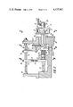
- FIG. 2 is a side view of an alternative embodiment of the proposed control apparatus, partially in section;
- FIG. 3 is a section view along line III--III in FIG. 2;
- FIG. 4 is a section view along line IV--IV in FIG. 2;
- FIG. 5 is a section view along line V--V in FIG. 2;
- FIG. 6 is a cyclogram of operation of a dobby
- FIGS. 7a, 7b, 7c, 7d show various mutual positions of comparison unit elements.
- the proposed apparatus for controlling the actuating mechanism of a loom dobby comprises a programming device with a program carrier 1 (FIG. 1) containing information on a change in both the state and position of a heald shaft 2, and having two outputs.
- a program carrier 1 FIG. 1
- One output delivering information on a change in the state of the heald shaft 2 via a coupling 3 is directly connected to a logical element 4, whereas the second output delivering information on a preset position of the heald shaft 2 is connected via a coupling 5 to a comparison unit 6.
- the input of the comparison unit 6 is connected to the output of an actuating mechanism 7 of the dobby via a feedback coupling 8.
- the output of the comparison unit 6 is connected via a time-delay element 9 and a coupling 10 to the logical element 4.
- the output of the logical element 4 is connected through a coupling 11 to the actuating mechanism 7 which, in turn, through a coupling 12, is connected to the heald shaft 2 of the loom.
- the program carrier 1 is a punched tape (not shown) adapted to move longitudinally upon a change in information.
- the kinematic coupling 3 between the program carrier 1 and the logical element 4 is a readout changeover needle 13 (FIG. 2) placed in a needle holder 14 secured on a change-over shaft 15 with the aid of a screw 16.
- This needle 13 serves to read out, from the punched tape, information on a change in the state of the actuating mechanism 7.
- the shaft 15, through the medium of a crank-arm 17 secured on this shaft by means of a screw 18, is coupled by a slot in arm 17 with a pin of a pin carrier 19 with a bush 20 of the logical element 4.
- the pin carrier 19 is in the form of an arm integral with the bush 20 and carrying a pin which is received in the slot of the arm 17 so as to provide in this way a pin-and-slot transmission between the arm 17 and the bush 20.
- the kinematic coupling 5 (FIG. 1) between the program carrier 1 and the comparison unit 6 includes a readout control needle 21 (FIG. 3) placed in a needle holder 22 secured on a control shaft 23 with the aid of a screw 24.
- This needle 21 serves to read out, from the program carrier 1, information on the preset position of the heald shaft 2.
- the shaft 23 (FIG. 2) through the medium of a crank-arm 25 secured on this shaft by means of a screw 26, is coupled with a tine 27 of a fork 28 of the comparison unit 6, the fork 28 being installed on the control shaft 23 so as to be turnable and axially movable thereon.
- a tubular shank 29 of the fork 28 there is made a slot 30. Through this slot 30 and an angle-piece 31, the fork 28 is coupled with the main shaft of the dobby (not shown) to be cyclically reciprocated back and forth, as shown by the double-headed arrow at the right of FIG. 2.
- the comparison unit 6 includes, in addition to the fork 28, a bush 32 with an elongated flange 33 also installed on the shaft 23 and acted on by a spring 34.
- This bush is support for turning movement by and extends into a housing 35 against which one end of the spring 34 abuts. The other end of this spring thrusts against one of the end faces of a bush 36.
- This bush 36 is set in the bush 20 of the logical element 4 and thrusts with the other end face against a shoulder 37 of the bush 32 of the comparison unit 6, the shoulder 37 bearing up against the housing 35. Installed in this housing are centers 38 wherein the changeover shaft 15 is rotatably arranged.
- the shaft 23 is supported for rotation in an opening of the wall of housing 35 against which one end of the spring 34 presses as well as in the interior of the bush 32, this shaft 23 also extending through the tubular shank 29 of the fork 28 so as to support the latter also for turning and axial movement.
- the time-delay element 9 is essentially a latch 40 coupled with the main shaft of the dobby to be reciprocated vertically thereby as shown by the double-headed arrow and thrusting against the bush 32 via the shoulder 37 when there is a discrepancy between the actual and the preset positions of the heald shaft 2.
- the bushes 32 and 36, the spring 34 and the shoulder 37 make up a kinematic coupling 10 between the comparison unit 6 and the logical element 4.
- the bush 20 of the logical element 4 is coaxially mounted on the bush 36 of the comparison unit 6 so as to be axially movable together with and rotatable around this bush.
- two stops "P” and “O” are arranged in a staggared manner.
- a rod 41 (FIG. 4) which is coupled with the main shaft of the dobby and used as a kinematic coupling 11 between the logical element 4 and the actuating mechanism 7.
- the output of the actuating mechanism i.e. the element determining the position of the heald shaft 2 at any moment of the operating cycle of the dobby, via a leverage 42 (FIG. 5) which is essentially the feedback coupling 8, is connected to the flange 33 of the bush 32 of the comparison unit 6.
- the program carrier 1 acts upon the readout needles 13 and 21 in accordance with curve "E" on a cyclogram (FIG. 6) and by moment “m” transmits, through the kinematic coupling 3, a signal to the logical element 4 thereby placing the latter relative to the rod 41 in an angular position corresponding to the information on a track of the program carrier 1 wherewith the changeover needle 13 cooperates.
- this track will be referred to as "changeover track.”
- the program carrier 1 via the kinematic coupling 5, transmits a signal to the fork 28 of the comparison unit 6 placing it relative to the flange 33 of the bush 32 in a position corresponding to the information on the track of the program carrier 1 with which the control needle 21 cooperates.
- this track will be referred to hereinbelow as "control track.”
- the flange 33 is placed by the actuating mechanism 7 via the feedback kinematic coupling 8 in a position corresponding to the actual position of the heald shaft 2.
- numerals I, II, III through XI in the first column denote operating cycles of the dobby.
- column “a” are indicated the preset positions of the heald shaft, the shaded squares corresponding to the upper position of the shaft and the unshaded ones corresponding to the lower position thereof.
- Registered in column “b” is information of the program carrier read out by the control needle 21, i.e. the control track.
- Registered in column “c” is information of the program carrier read out by the changeover needle 13, i.e. the changeover track.
- the program carrier 1 executes its motion (curve D of FIG. 6) away from the readout needles (13, 21), after which, during the time interval from moment “t” to moment “v,” the program carrier 1 moves (curve E of FIG. 6) longitudinally by one card, thereby setting new changeover and control tracks against respective needles.
- the program carrier 1 moves towards the readout needles 13, 21 and, since in the changeover card of the second cycle there is no hole (Table 1, position II-c) and the logical element 4 is held by the latch 40 in the shifted position, the stop “O” is set against the rod 41, i.e. the "reverse” signal (Table 1, position II-d) is initiated.
- the heald shaft is disengaged and lifted (Table 1, position III-e 1 , position III-f 1 ). Since, during this cycle, the actual position of the heald shaft coincides with the preset one, i.e. the heald shaft should be and is lifted (Table 1, position III-a), the mutual arrangement of the fork 28 and of the flange 33 of the bush 32 is as that shown in FIG. 7b. In this case, the tines 27 coincide with the holes 39 of the flange 33 and the fork 28, while moving (the curve F of FIG. 6), leaves the flange 33 and the logical element 4 coupled therewith in the initial position, i.e.
- the heald shaft operates in a stable mode when during each cycle the holes of the flange 33 coincide with the tines 27 of the fork 28 of the comparison unit 6, as is shown in FIGS. 7a and 7b, the meaning of the information of the changeover track of the program carrier 1 remaining "direct".
- the above-described structure of the invention forms an apparatus which is adapted to control the actuating mechanism of a loom dobby, this apparatus including a logic means 4 formed by the bush 20 which is supported by a support means which includes the bush 36 and the shaft 23 extending therethrough.
- This support means supports the logic means for movement between a normal location, shown in FIG. 2, and a displaced location in which the stop O is situated in the plane of the output means 41.
- the output means 41 of the logic means 4 is operatively connected in a known way to a heald shaft for controlling the position thereof.
- the logic means 4 is capable of being placed in first or second angular positions by way of the program-responsive means formed by components 13-19, this program-responsive means being operatively connected with the logic means 4 to place the latter in either its first or second angular position depending upon the information at the punched card of the program means.
- the stop P of the logic means is in line with the output means 41 so as to provide one type of operation therethrough, in this first angular position of the logic means 4 while it is in the illustrated normal location.
- the stop P In its second angular position, while in its normal location, the stop P will be turned beyond the output means 41 so that a second type of operation will be provided therethrough.
- the fork 28 of the comparison unit 6 forms a sensing means for sensing the actual position of the heald shaft.
- This sensing means 28 is operatively connected with the cyclically operating means 31 to be cyclically moved thereby along a given path of movement.
- the components 21-23 and 25-27 form a second program-responsive means operatively connected to the sensing means 28 for placing the latter in either one of at least a pair of predetermined angular positions, in accordance with the particular information which is received by this second program-responsive means from the program means.
- the elongated flange 33 together with its tubular bush 32 forms an indicating means operatively connected with the element controlled by the output means 41, namely the heald shaft, to indicate the actual position thereof.
- This indicating means 33 is automatically positioned, by way of the transmission which includes the component 42 shown in FIG. 5, in either one of at least a pair of positions which will respectively either register with the position of the sensing means 28 or will not register therewith.
- This indicating means 33 is situated along the path of movement of the sensing means 28 in such a way as to remain out of engagement therewith when the indicating means 33 is in the position registering with the position of the sensing means 28.
- the indicating means 33 is in a non-registering position with respect to the sensing means 28, then when the latter is cyclically moved along its path of movement by the means 31, the sensing means 28 will through its tines 27 displace the indicating means 33, and this indicating means 33 is operatively connected through its bush 32 and flange 37 with the logic means 4 so as to displace the latter from its normal location to its displaced location.
- the spring 34 of course forms a spring means for yieldably maintaining the logic means in its normal location.
- the delay means 9 formed by the reciprocating latch 40 cooperates with the flange 37 for temporarily maintaining the logic means 4 in its displaced location so that the information transmitted to the logic means 4 by way of the first program-responsive 13-19 will be reversed as described above. After a given cycle of operation the delay means releases the logic means to be returned by the spring means 34 back to its normal location.
Landscapes
- Engineering & Computer Science (AREA)
- Textile Engineering (AREA)
- Looms (AREA)
- Auxiliary Weaving Apparatuses, Weavers' Tools, And Shuttles (AREA)
Applications Claiming Priority (2)
| Application Number | Priority Date | Filing Date | Title |
|---|---|---|---|
| SU2334101 | 1976-03-31 | ||
| SU762334101A SU609796A1 (ru) | 1976-03-31 | 1976-03-31 | Механизм управлени ремизоподъемной каретки ткацкого станка |
Publications (1)
| Publication Number | Publication Date |
|---|---|
| US4137951A true US4137951A (en) | 1979-02-06 |
Family
ID=20652137
Family Applications (1)
| Application Number | Title | Priority Date | Filing Date |
|---|---|---|---|
| US05/780,188 Expired - Lifetime US4137951A (en) | 1976-03-31 | 1977-03-22 | Apparatus for controlling actuating mechanism of loom dobby |
Country Status (6)
| Country | Link |
|---|---|
| US (1) | US4137951A (OSRAM) |
| JP (1) | JPS52144462A (OSRAM) |
| CH (1) | CH621160A5 (OSRAM) |
| DE (1) | DE2714210C3 (OSRAM) |
| FR (1) | FR2346477A1 (OSRAM) |
| SU (1) | SU609796A1 (OSRAM) |
Families Citing this family (2)
| Publication number | Priority date | Publication date | Assignee | Title |
|---|---|---|---|---|
| DE3136818C2 (de) * | 1980-09-19 | 1990-08-02 | Hitachi Chemical Co., Ltd., Tokio/Tokyo | Verwendung eines lichtempfindlichen Gemisches und eines lichtempfindlichen Aufzeichnungsmaterials zur Bildung einer Lötmaske |
| NL8005904A (nl) | 1980-10-28 | 1982-05-17 | Rueti Te Strake Bv | Spoelloze weefmachine. |
Citations (5)
| Publication number | Priority date | Publication date | Assignee | Title |
|---|---|---|---|---|
| US2085459A (en) * | 1935-08-03 | 1937-06-29 | Saurer Ag Adolph | Pattern mechanism for looms and the like |
| US2926703A (en) * | 1960-03-01 | Controlling device | ||
| US3060975A (en) * | 1960-04-26 | 1962-10-30 | Sulzer Ag | Method and means for scanning a pattern card of a dobby |
| US3554238A (en) * | 1967-04-25 | 1971-01-12 | Staeubli Ag | Dobbies |
| SU418580A1 (ru) * | 1971-08-05 | 1974-03-05 | Устройство для считывания программыс перфорированной ленты ре?лизоподъемнойкаретки ткацкого станка |
-
1976
- 1976-03-31 SU SU762334101A patent/SU609796A1/ru active
-
1977
- 1977-03-22 US US05/780,188 patent/US4137951A/en not_active Expired - Lifetime
- 1977-03-23 CH CH368577A patent/CH621160A5/de not_active IP Right Cessation
- 1977-03-29 FR FR7709379A patent/FR2346477A1/fr active Granted
- 1977-03-30 DE DE2714210A patent/DE2714210C3/de not_active Expired
- 1977-03-31 JP JP3691977A patent/JPS52144462A/ja active Pending
Patent Citations (5)
| Publication number | Priority date | Publication date | Assignee | Title |
|---|---|---|---|---|
| US2926703A (en) * | 1960-03-01 | Controlling device | ||
| US2085459A (en) * | 1935-08-03 | 1937-06-29 | Saurer Ag Adolph | Pattern mechanism for looms and the like |
| US3060975A (en) * | 1960-04-26 | 1962-10-30 | Sulzer Ag | Method and means for scanning a pattern card of a dobby |
| US3554238A (en) * | 1967-04-25 | 1971-01-12 | Staeubli Ag | Dobbies |
| SU418580A1 (ru) * | 1971-08-05 | 1974-03-05 | Устройство для считывания программыс перфорированной ленты ре?лизоподъемнойкаретки ткацкого станка |
Also Published As
| Publication number | Publication date |
|---|---|
| DE2714210C3 (de) | 1981-01-22 |
| DE2714210A1 (de) | 1977-10-20 |
| CH621160A5 (OSRAM) | 1981-01-15 |
| DE2714210B2 (de) | 1980-05-08 |
| SU609796A1 (ru) | 1978-06-05 |
| JPS52144462A (en) | 1977-12-01 |
| FR2346477B1 (OSRAM) | 1980-07-11 |
| FR2346477A1 (fr) | 1977-10-28 |
Similar Documents
| Publication | Publication Date | Title |
|---|---|---|
| US2755754A (en) | Sewing machine with zigzag arrangement | |
| US2832302A (en) | Sewing machine | |
| US4137951A (en) | Apparatus for controlling actuating mechanism of loom dobby | |
| US2900937A (en) | Sewing machines | |
| AU560875B2 (en) | A feeding mechanism in a sewing machine | |
| KR860000961Y1 (ko) | 버튼 정위장치 | |
| US4444136A (en) | Device for interrupting a needle bar drive | |
| CA1091333A (en) | Sewing machine with a stitch pattern selecting device | |
| US4344162A (en) | Automatic record changing apparatus | |
| US4063525A (en) | Automatic zigzag sewing machine | |
| US3217677A (en) | Ornamental stitch sewing machine | |
| US3433092A (en) | Pattern cam selecting arrangement | |
| US3091200A (en) | Pattern cam arrangement for sewing machines | |
| US3455258A (en) | Automatic feed changing device in zigzag sewing machine | |
| US3965830A (en) | Assembly for automatic bar tacking | |
| US3435788A (en) | Sewing machine | |
| US4106419A (en) | Sewing machine | |
| US4113081A (en) | Mechanism for actuating a member of a typewriter | |
| US3077846A (en) | Arrangement for engaging and disengaging the mechanism controlling the movement of the needle-carrying bars in sewing machines provided with two needles | |
| US4580515A (en) | Multiple needle sewing machine | |
| US4552184A (en) | Method and apparatus for controlling a rotation dobby | |
| US3085526A (en) | Sititch pattern control means for zigzag sewing machine | |
| US4289086A (en) | Needle bar coupling in an embroidering machine | |
| US4359954A (en) | Skipped-stitch mechanism on a sewing machine | |
| US4393794A (en) | Sewing machine with needle dropping hole changing control device |