US4136922A - Ignition cable terminals - Google Patents
Ignition cable terminals Download PDFInfo
- Publication number
- US4136922A US4136922A US05/824,903 US82490377A US4136922A US 4136922 A US4136922 A US 4136922A US 82490377 A US82490377 A US 82490377A US 4136922 A US4136922 A US 4136922A
- Authority
- US
- United States
- Prior art keywords
- core
- arms
- base
- terminal
- jacket
- Prior art date
- Legal status (The legal status is an assumption and is not a legal conclusion. Google has not performed a legal analysis and makes no representation as to the accuracy of the status listed.)
- Expired - Lifetime
Links
Images

Classifications
-
- H—ELECTRICITY
- H01—ELECTRIC ELEMENTS
- H01T—SPARK GAPS; OVERVOLTAGE ARRESTERS USING SPARK GAPS; SPARKING PLUGS; CORONA DEVICES; GENERATING IONS TO BE INTRODUCED INTO NON-ENCLOSED GASES
- H01T13/00—Sparking plugs
- H01T13/02—Details
- H01T13/04—Means providing electrical connection to sparking plugs
-
- H—ELECTRICITY
- H01—ELECTRIC ELEMENTS
- H01R—ELECTRICALLY-CONDUCTIVE CONNECTIONS; STRUCTURAL ASSOCIATIONS OF A PLURALITY OF MUTUALLY-INSULATED ELECTRICAL CONNECTING ELEMENTS; COUPLING DEVICES; CURRENT COLLECTORS
- H01R43/00—Apparatus or processes specially adapted for manufacturing, assembling, maintaining, or repairing of line connectors or current collectors or for joining electric conductors
Definitions
- This invention relates to terminals of the kind especially adapted for use with an ignition cable having a core projecting beyond one end of an insulating jacket.
- Terminals constructed according to the invention are especially adapted for use with an ignition cable having a core formed of nonmetallic material, but which is provided with conductive material on its surface.
- Ignition cables of the kind with which terminals constructed according to the invention are especially adapted for use conventionally comprise a non-metallic core strong in tension provided on its surface with material having radio frequency suppression characteristics.
- the core is located at the center of an insulating jacket which conventionally is composed of an intermediate sheath of a braided textile or glass fiber material and over which is an outer sheath of relatively soft silicone or other rubbery material.
- the fitting of terminals to cables of the kind described has been accomplished largely by stripping the insulating jacket from one end of the cable so as to expose a length of the core.
- the core is then doubled back along the adjacent end of the jacket and one end of a tubular, metallic terminal is fitted over both the jacket and the doubled back core.
- the tubular end of the terminal then is crimped or radially compressed tightly about the jacket and the doubled back core so as to effect physical engagement between the terminal and the conductive material on the core.
- the crimped end of the terminal conventionally is provided with inwardly directed barbs or teeth which pierce the rubbery jacket and imbed themselves in the woven braid so as to provide greater pull-off strength between the terminal and the cable than is possible to obtain simply by imbedding the barbs in the rubbery jacket alone.
- the double back core becomes imbedded in the relatively soft, rubbery insulating sheath, but immediately following the crimping operation the conductive material on the core nevertheless engages the terminal inasmuch as the inherent resiliency of the rubbery material constantly exerts a radially outward force on the core to urge it toward the terminal portion which encircles the jacket.
- the cable is fitted to an automotive engine, however, the combined effects of time and temperature changes to which the terminal and cable are subjected causes the rubbery material in which the core is embeded to take a permanent set. That is, the rubbery material loses its resilience and no longer urges the doubled back core radially outwardly into engagement with the terminal. It thus is possible for a small clearance to exist between the terminal and the conductive material on the core.
- a small clearance between the conductive material on the core and the terminal normally does not prevent the cable from functioning when the engine to which it is fitted is operating. This is because the voltage carried by the core during engine operation is sufficiently great to establish an arc which spans such clearance.
- the presence of such clearance is disadvantageous for other reasons. For example, when an ignition cable having such a clearance between its core and its terminal is tested by electronic ignition analyzing mechanisms, the existence of the clearance often indicates that the cable is inoperative, thereby resulting in its replacement. Further, the presence of arcs between the core and the terminal adversely affects the conductive material on the core, particularly in those instances in which the conductive material comprises carbon particles with which the non-metallic core is coated or impregnated.
- a further disadvantage of the doubled back cable and terminal assembly is that a considerable length of the core must project from the jacket to provide a sufficient core length to be doubled back.
- the cable initially must be manufactured to a length greater than that of the finished cable. Since the insulating jacket must be stripped from the core prior to the doubling back of the latter, this construction not only results in waste of significant amounts of jacketing material, but also necessitates the use of considerably greater lengths of core material.
- An object of this invention is to provide an ignition cable and terminal assembly which overcomes or greatly minimizes the disadvantages referred to above.
- Another object of the invention is to provide a terminal for an ignition cable and which assures excellent conductivity between the terminal and the core throughout the life of the assembly.
- a further object of the invention is to provide a terminal of the character described and which may be assembled on an ignition cable in such manner that the core of the cable assists in retaining the terminal on the cable.
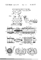
- FIG. 1 is a plan view of a blank of metal from which a terminal according to one embodiment of the invention may be formed;
- FIG. 2 is a top plan view illustrating a partially formed terminal in condition to be applied to an ignition cable
- FIG. 3 is a side elevational view of the assembly shown in FIG. 2, but illustrating the terminal fully assembled with the cable;
- FIG. 4 is a sectional view taken on the line 4--4 of FIG. 2;
- FIG. 5 is a sectional view taken on the line 5--5 of FIG. 2;
- FIG. 6 is a sectional view taken on the line 6--6 of FIG. 3;
- FIG. 7 is a view similar to FIG. 3, but illustrating a modification
- FIG. 8 is a view like FIG. 1, but illustrating a blank for forming a modified embodiment of the terminal
- FIG. 9 is a top view illustrating the partially formed terminal in condition to be applied to a cable
- FIG. 10 is a side view of the assembly of FIG. 9, but illustrating the terminal fully applied to a cable;
- FIGS. 11 and 12 are sectional views taken on the lines 11--11 and 12--12, respectively, of FIG. 9;
- FIG. 13 is a side view illustrating the terminal of FIG. 10 bent between its ends.
- FIG. 14 is a sectional view taken on the line 14--14 of FIG. 13.
- a terminal constructed according to any of the disclosed embodiments of the invention is especially adapted for use with an ignition cable 1 having a core 2 formed of non-metallic material having an extremely high degree of tensile strength.
- the core may be formed of a suitable material such as solid glass fiber strands, or a plurality of glass fiber rovings, or a glass fiber rope, or any other material having the requisite tensile strength.
- the core should be capable of suppressing radio frequency radiations and, if it is to be of the inductive impedance type, the core may be wound spirally around its surface with a metallic, conductive fine wire 3 as is shown in FIGS. 2 and 3.
- the core may have its surface coated or impregnated with conductive particles such as carbon or the like (not shown).
- the core preferably is encased within a sheath 4 formed of braided textile or glass fibers, and the sheath 4 is encased within an insulating jacket 5 formed of silicone or other rubbery material. The sheath and the jacket are stripped from one end of the core in a conventional manner, so that a desired length of the core projects beyond the jacket.
- a terminal constructed according to the embodiment illustrated in FIGS. 1-6 is indicated generally by the reference character 6 and is formed from a blank 7 of conductive metal which is cut from a metal strip 8 by conventional progressive dies (not shown). The blank terminates at one end in a flange 9 and at the other end in a flange 10. Between the flanges 9 and 10 is an intermediate body portion 11 having laterally extending tabs 12.
- the flange 10 is rolled to form a cylindrical socket 13 adapted to accommodate a spark plug electrode (not shown).
- the confronting ends of the flange meet to form a split seam 14 and may be provided with interlocking fingers 15 which underlie a generally C-shaped spring clip 16 having projection 17 adjacent the ends thereof which extend through correspondingly spaced openings 18 formed in the flange so as to enable the projections to provide yieldable gripping means for the electrode.
- the flange 9 at the opposite end of the blank 7 is rolled into a trough-like configuration having upstanding legs 19 and axially spaced grooves 20. Along each groove the flange 9 is upset at circumferentially spaced intervals to provide barbs or teeth 21 which extend inwardly of the trough defined by the legs 19.
- the legs 19 are adapted to be rolled to form a cylindrical anchor sleeve 22 which may be crimped tightly about the jacket 5, thereby causing the barbs 21 to imbed themselves in the jacket and to force those portions of the jacket 5 between adjacent grooves 20 to expand radially.
- the cylinder 22 has a longitudinal axis X which coincides with the longitudinal axis of the cable 1.
- the intermediate body portion 11 of the terminal 6 between the tabs 12 preferably remains flat, but is offset by means of a conventional die process, relative to the longitudinal axis of the cylinder 22.
- the amount of offset preferably is such that the inner surface of the body portion 11 is spaced from the axis X by an amount corresponding substantially to the radius of the core 2, thereby providing a base 23 on which the projecting end of the core 2 may be supported with its longitudinal axis coinciding with that of the jacketed core.
- the projecting end of the core therefore, need not be kinked or bent.
- the tabs 12 are bent outwardly and upwardly from the base 23, by a conventional die process, to form upstanding arms 24 which are joined at corresponding ends to the base 23, but which are free at their opposite ends 25.
- the arms 24 are rolled between their ends toward one another and toward the base 23 to provide smoothly curved clamp surfaces 26 which confront one another and overlie the base 23 to form with the latter a triangular clamping zone.
- the initial spacing between the curved surfaces 26 is such that the bared core 2 may be accommodated on the base and encircled by the latter and the curved arm portions 26 and without engaging the arms.
- the length of each arm 24 and the radius on which it is rolled preferably are such that the free ends 25 of the arms are spaced from the base 23 a distance less than the radius of the core 2.
- the arms 24 are bent toward one another from the position shown in FIG. 5 to the positions shown in FIG. 6. Those curved portions 26 of the arms 24 which confront the core 2 thus will be moved forcibly into engagement with the core, and with the conductor 3 on the core 2, so as to clamp the core tightly and directly between the arms and the base 23.
- the force with which the arm portions 26 grip the core may be such as to deform the core into a substantially triangular configuration, as is indicated in FIG. 6, thereby providing indentations 27 in the core occupied by the adjacent arm portions 26 and resulting in an extremely strong connection between the terminal and the core.
- the purpose of locating the free ends 25 of the arms 24 initially at a distance from the base 23 which is less than the radius of the core 2 is to assure that, during bending of the arms from the positions shown in FIG. 5 to the positions shown in FIG. 6, the free ends 25 do not engage either the core 2 or the conductor 3.
- the relatively sharp edges of the free ends 25 thus cannot engage and cut the conductor 3. Instead, engagement between the conductor 3 and the arms occurs only along the smoothly rounded surfaces 26.
- the terminal When a cable and terminal have been assembled in the manner described, the terminal not only is fixed to the cable by means of the barbs 21, but also is fixed to the cable by the reaction between the base 23, the clamping arms 24 and the core 2.
- the tensile strength of the core thus may be availed of to maintain the terminal and cable assembled.
- FIG. 7 corresponds substantially to that disclosed in FIGS. 1-6 with the exception that the modified embodiment has a cylindrical socket 13a which is longer than the socket 13 and has its walls cut away on opposite sides thereof to provide substantially V-shaped openings 30.
- the openings 30 make it possible for the socket 13a to be bent about an arc so that the socket 13a and the anchor cylinder 22 form therebetween an included angle of between 90° and less than 180°.
- the terminal construction illustrated in FIG. 7 corresponds to that described earlier.
- a terminal 31 constructed in accordance with the embodiment disclosed in FIGS. 8-14 is formed from a blank 32 of conductive metal strip 33 by conventional progressive dies (not shown).
- the blank terminates at one end in a flange 34 and at the opposite end in a flange 35.
- an intermediate body portion 36 having laterally extending arms or flanges 37 and tabs 38.
- the flange 34 is rolled to form a cylindrical socket 39 that is adapted to accommodate a spark plug electrode and is provided with interlocking fingers 40 over which is placed a conventional C-shaped spring clip 41 having projections 42 which extend through openings 43 formed in the flange 34.
- the flange 35 is upset at spaced intervals to form teeth or barbs 44 and is rolled into a trough-like configuration having upstanding legs 45 and axially spaced grooves 46.
- the legs 45 may be rolled to form a cylindrical anchor sleeve 47 that is crimped tightly about the jacket 5, thereby causing the barbs 44 to imbed themselves in the jacket and anchor the terminal 31 to the ignition cable 1.
- the anchor sleeve 47 has a longitudinal axis Y which coincides with the longitudinal axis of the cable 1.
- the intermediate body portion 36 is offset upwardly so that its upper surface is spaced from the axis Y by an amount corresponding substantially to the radius of the core 2, thereby providing a base 48 on which the projecting end of the core 2 may be supported with its longitudinal axis coinciding with that of the jacketed core.
- the flanges 37 and the tabs 38 associated with the intermediate body portion 36 are rolled upwardly so that the flanges 37 form upstanding, spaced apart arms 49 and the tabs 38 are rolled toward one another to form a sleeve 50 of the same size as the socket 39.
- the arms 49 are deformed toward one another to provide indentations 51 which overhang the base 48, and together with the latter form a triangular clamping zone.
- the indentations initially are spaced a sufficient distance apart to permit introduction of the core 2 between them with the core encircled by the indentations and the base.
- the indentations 51 are essentially V-shaped, but have confronting clamp surfaces 52 that are rounded, rather than sharp.
- the indented portions of the arms terminate in free ends 53 which are rolled outwardly along a radius to provide smoothly curved surfaces 54. The rolling of the arm portions is accomplished by conventional dies.
- the indented portions 51 of the arms 49 are deformed toward one another and toward the base 48 so as to move from the positions shown in FIG. 11 to the positions shown in FIG. 14 in which latter positions the core 2 is clamped tightly and directly between the indented portions of the arms and the base 48.
- the height of the arms 49 is such that the core 2 will be engaged by the rounded portions 54 of the respective arms.
- the outward curling of the free ends 53 of the arms assures that the sharp edges of the free ends of the arms will not engage either the core or the conductive material thereon.
- the arms 49 may grip the core with such force as to deform the latter into a substantially triangular configuration to provide an extremely strong connection between the terminal and the core.
- the terminal may have the configuration shown in FIG. 10 or, if desired, it may be bent between its ends so that the socket 39 and the anchor sleeve 47 form an included angle therebetween.
- the indented portions 51 of the arms 49 provide a convenient zone at which to effect bending of the terminal by conventional bending dies (not shown).
- the included angle formed between the opposite ends of the terminal thus may be any desired angle between 90° and less than 180°.
Landscapes
- Engineering & Computer Science (AREA)
- Manufacturing & Machinery (AREA)
- Connections Effected By Soldering, Adhesion, Or Permanent Deformation (AREA)
- Spark Plugs (AREA)
- Cable Accessories (AREA)
- Ignition Installations For Internal Combustion Engines (AREA)
Applications Claiming Priority (1)
| Application Number | Priority Date | Filing Date | Title |
|---|---|---|---|
| US59836375A | 1975-07-23 | 1975-07-23 |
Related Parent Applications (1)
| Application Number | Title | Priority Date | Filing Date |
|---|---|---|---|
| US59836375A Continuation | 1975-07-23 | 1975-07-23 |
Publications (1)
| Publication Number | Publication Date |
|---|---|
| US4136922A true US4136922A (en) | 1979-01-30 |
Family
ID=24395263
Family Applications (1)
| Application Number | Title | Priority Date | Filing Date |
|---|---|---|---|
| US05/824,903 Expired - Lifetime US4136922A (en) | 1975-07-23 | 1977-08-15 | Ignition cable terminals |
Country Status (7)
| Country | Link |
|---|---|
| US (1) | US4136922A (de) |
| JP (2) | JPS5215934A (de) |
| CA (1) | CA1083684A (de) |
| DE (1) | DE2632387C2 (de) |
| ES (1) | ES450026A1 (de) |
| FR (1) | FR2319223A1 (de) |
| GB (1) | GB1554910A (de) |
Cited By (9)
| Publication number | Priority date | Publication date | Assignee | Title |
|---|---|---|---|---|
| US4274695A (en) * | 1978-02-03 | 1981-06-23 | Hitachi, Ltd. | Device for electrically connecting spark plug to high-voltage cable |
| US5156555A (en) * | 1990-08-23 | 1992-10-20 | Leopold Kostal Gmbh & Co. | Electrical connection device |
| EP0780928A3 (de) * | 1995-12-22 | 1998-08-12 | Delphi Automotive Systems Deutschland GmbH | Einteiliges Kontaktelement |
| US5890926A (en) * | 1997-03-26 | 1999-04-06 | The Whitaker Corporation | Cable bend controller |
| US20050118885A1 (en) * | 2003-12-02 | 2005-06-02 | Fci Americas Technology, Inc. | Electrical connector and connector tool |
| US20090075528A1 (en) * | 2007-09-17 | 2009-03-19 | Thomas & Betts International, Inc. | 90-Degree ferrule and pin terminals |
| US20160030037A1 (en) * | 2011-02-10 | 2016-02-04 | Coloplast A/S | Suture assembly including a suture clip |
| US20170025798A1 (en) * | 2014-04-01 | 2017-01-26 | CommScope Connectivity Spain, S.L. | Shielded telecommunications connector |
| US10363027B2 (en) | 2010-12-02 | 2019-07-30 | Coloplast A/S | Suture assembly including a suture attached to a leader |
Families Citing this family (12)
| Publication number | Priority date | Publication date | Assignee | Title |
|---|---|---|---|---|
| US4209221A (en) * | 1978-09-27 | 1980-06-24 | General Motors Corporation | Two-piece socket terminal |
| JPH0231994Y2 (de) * | 1987-09-10 | 1990-08-29 | ||
| DE202007005264U1 (de) * | 2007-04-10 | 2008-08-14 | Weidmüller Interface GmbH & Co. KG | Schirmhülse |
| US10364572B2 (en) | 2014-08-30 | 2019-07-30 | Innovative Building Technologies, Llc | Prefabricated wall panel for utility installation |
| US10260250B2 (en) | 2014-08-30 | 2019-04-16 | Innovative Building Technologies, Llc | Diaphragm to lateral support coupling in a structure |
| AU2017229471B2 (en) | 2016-03-07 | 2019-08-08 | Innovative Building Technologies, Llc | Waterproofing assemblies and prefabricated wall panels including the same |
| KR102279403B1 (ko) | 2016-03-07 | 2021-07-21 | 이노베이티브 빌딩 테크놀러지스 엘엘씨 | 유틸리티 설치를 위한 미리 조립된 벽 패널 |
| JP6786617B2 (ja) | 2016-03-07 | 2020-11-18 | イノベイティブ ビルディング テクノロジーズ,エルエルシー | 外部導管係合特徴部を備えたプレハブ式間仕切り壁 |
| EP3426982A4 (de) | 2016-03-07 | 2019-10-16 | Innovative Building Technologies LLC | Boden- und deckenpaneel für plattenfreies bodensystem eines gebäudes |
| US11098475B2 (en) | 2017-05-12 | 2021-08-24 | Innovative Building Technologies, Llc | Building system with a diaphragm provided by pre-fabricated floor panels |
| US10724228B2 (en) | 2017-05-12 | 2020-07-28 | Innovative Building Technologies, Llc | Building assemblies and methods for constructing a building using pre-assembled floor-ceiling panels and walls |
| US10487493B2 (en) | 2017-05-12 | 2019-11-26 | Innovative Building Technologies, Llc | Building design and construction using prefabricated components |
Citations (10)
| Publication number | Priority date | Publication date | Assignee | Title |
|---|---|---|---|---|
| US1706005A (en) * | 1922-01-26 | 1929-03-19 | Western Electric Co | Method of making cord tips |
| US2288918A (en) * | 1941-03-24 | 1942-07-07 | Gen Motors Corp | Wiring connector socket |
| US2535013A (en) * | 1946-03-20 | 1950-12-19 | Aircraft Marine Prod Inc | Electrical connector |
| US2789278A (en) * | 1953-05-01 | 1957-04-16 | Controls Company | Electrical connection and method of making the same |
| US3112150A (en) * | 1956-08-16 | 1963-11-26 | Aircraft Marine Prod Inc | Electrical connections |
| US3278889A (en) * | 1964-06-17 | 1966-10-11 | Essex Wire Corp | Terminal connectors for wire wound ignition cables |
| US3383457A (en) * | 1966-04-05 | 1968-05-14 | Amp Inc | Connector means for connecting coaxial cable to a printed circuit board |
| US3404368A (en) * | 1965-08-04 | 1968-10-01 | Amp Inc | Electrical connector of the plug or socket variety |
| US3683309A (en) * | 1970-03-20 | 1972-08-08 | Yazaki Corp | High frequency noise prevention cable |
| US3740702A (en) * | 1971-05-21 | 1973-06-19 | F Moray | Electrical wire terminal |
Family Cites Families (4)
| Publication number | Priority date | Publication date | Assignee | Title |
|---|---|---|---|---|
| FR900036A (fr) * | 1943-07-20 | 1945-06-18 | Progil | Procédé de désherbage sélectif |
| US3335392A (en) * | 1965-07-19 | 1967-08-08 | Essex Wire Corp | Terminal construction |
| US3597723A (en) * | 1970-05-01 | 1971-08-03 | Microdot Inc | Spark plug terminal |
| DE2460397A1 (de) * | 1974-12-20 | 1976-06-24 | Grote & Hartmann | Zuendkerzenstecker |
-
1976
- 1976-07-05 CA CA256289A patent/CA1083684A/en not_active Expired
- 1976-07-19 GB GB29899/76A patent/GB1554910A/en not_active Expired
- 1976-07-19 DE DE2632387A patent/DE2632387C2/de not_active Expired
- 1976-07-21 JP JP51087118A patent/JPS5215934A/ja active Pending
- 1976-07-22 ES ES450026A patent/ES450026A1/es not_active Expired
- 1976-07-22 FR FR7622324A patent/FR2319223A1/fr active Granted
-
1977
- 1977-08-15 US US05/824,903 patent/US4136922A/en not_active Expired - Lifetime
-
1984
- 1984-09-17 JP JP1984140784U patent/JPS6065993U/ja active Pending
Patent Citations (10)
| Publication number | Priority date | Publication date | Assignee | Title |
|---|---|---|---|---|
| US1706005A (en) * | 1922-01-26 | 1929-03-19 | Western Electric Co | Method of making cord tips |
| US2288918A (en) * | 1941-03-24 | 1942-07-07 | Gen Motors Corp | Wiring connector socket |
| US2535013A (en) * | 1946-03-20 | 1950-12-19 | Aircraft Marine Prod Inc | Electrical connector |
| US2789278A (en) * | 1953-05-01 | 1957-04-16 | Controls Company | Electrical connection and method of making the same |
| US3112150A (en) * | 1956-08-16 | 1963-11-26 | Aircraft Marine Prod Inc | Electrical connections |
| US3278889A (en) * | 1964-06-17 | 1966-10-11 | Essex Wire Corp | Terminal connectors for wire wound ignition cables |
| US3404368A (en) * | 1965-08-04 | 1968-10-01 | Amp Inc | Electrical connector of the plug or socket variety |
| US3383457A (en) * | 1966-04-05 | 1968-05-14 | Amp Inc | Connector means for connecting coaxial cable to a printed circuit board |
| US3683309A (en) * | 1970-03-20 | 1972-08-08 | Yazaki Corp | High frequency noise prevention cable |
| US3740702A (en) * | 1971-05-21 | 1973-06-19 | F Moray | Electrical wire terminal |
Non-Patent Citations (1)
| Title |
|---|
| IBM Bulletin, Cioffi et al., Wire Barrel Connector, vol. 8, No. 10, Mar.-1966, p. 1328. * |
Cited By (17)
| Publication number | Priority date | Publication date | Assignee | Title |
|---|---|---|---|---|
| US4274695A (en) * | 1978-02-03 | 1981-06-23 | Hitachi, Ltd. | Device for electrically connecting spark plug to high-voltage cable |
| US5156555A (en) * | 1990-08-23 | 1992-10-20 | Leopold Kostal Gmbh & Co. | Electrical connection device |
| EP0780928A3 (de) * | 1995-12-22 | 1998-08-12 | Delphi Automotive Systems Deutschland GmbH | Einteiliges Kontaktelement |
| US5885117A (en) * | 1995-12-22 | 1999-03-23 | Delphi Automotive Systems Deutschland Gmbh | One-part contact element |
| US5890926A (en) * | 1997-03-26 | 1999-04-06 | The Whitaker Corporation | Cable bend controller |
| US20050118885A1 (en) * | 2003-12-02 | 2005-06-02 | Fci Americas Technology, Inc. | Electrical connector and connector tool |
| US7070462B2 (en) * | 2003-12-02 | 2006-07-04 | Fci Americas Technology, Inc. | Electrical connector with expandable tubular clamping sections |
| US20090075528A1 (en) * | 2007-09-17 | 2009-03-19 | Thomas & Betts International, Inc. | 90-Degree ferrule and pin terminals |
| US10363027B2 (en) | 2010-12-02 | 2019-07-30 | Coloplast A/S | Suture assembly including a suture attached to a leader |
| US20160030037A1 (en) * | 2011-02-10 | 2016-02-04 | Coloplast A/S | Suture assembly including a suture clip |
| US10278691B2 (en) * | 2011-02-10 | 2019-05-07 | Coloplast A/S | Suture assembly including a suture clip |
| CN106797077A (zh) * | 2014-04-01 | 2017-05-31 | 康普连通西班牙公司 | 屏蔽式通信连接器 |
| US9979133B2 (en) * | 2014-04-01 | 2018-05-22 | CommScope Connectivity Spain, S.L. | Shielded telecommunications connector |
| US20170025798A1 (en) * | 2014-04-01 | 2017-01-26 | CommScope Connectivity Spain, S.L. | Shielded telecommunications connector |
| US10498088B2 (en) * | 2014-04-01 | 2019-12-03 | CommScope Connectivity Spain, S.L. | Shielded telecommunications connector |
| US10958018B2 (en) | 2014-04-01 | 2021-03-23 | CommScope Connectivity Spain, S.L. | Shielded telecommunications connector |
| US11476622B2 (en) | 2014-04-01 | 2022-10-18 | CommScope Connectivity Spain, S.L. | Shielded telecommunications connector |
Also Published As
| Publication number | Publication date |
|---|---|
| CA1083684A (en) | 1980-08-12 |
| DE2632387C2 (de) | 1985-08-22 |
| JPS6065993U (ja) | 1985-05-10 |
| FR2319223A1 (fr) | 1977-02-18 |
| DE2632387A1 (de) | 1977-02-17 |
| FR2319223B1 (de) | 1980-10-03 |
| GB1554910A (en) | 1979-10-31 |
| JPS5215934A (en) | 1977-02-05 |
| ES450026A1 (es) | 1977-07-16 |
Similar Documents
| Publication | Publication Date | Title |
|---|---|---|
| US4136922A (en) | Ignition cable terminals | |
| US2816275A (en) | Electrical connector | |
| US4010538A (en) | Phono plug | |
| US5685072A (en) | Cable clamp apparatus and method | |
| US3404368A (en) | Electrical connector of the plug or socket variety | |
| CA1283720C (en) | Electrical connector having resilient contact means | |
| EP3641061B1 (de) | Abgeschirmte kabelanordnung | |
| US2302767A (en) | Terminal for electrical conductors | |
| US4209221A (en) | Two-piece socket terminal | |
| US6290556B1 (en) | Two piece male pin terminal connector | |
| EP0000996A1 (de) | Elektrischer Verbinder | |
| US3546365A (en) | Grounding connector for connection onto a shield of a conductor means | |
| US3774141A (en) | Terminal connector and insulating sleeve therefor | |
| JPH11144776A (ja) | 同軸ケーブル用コネクタの接続構造及びその接続方法 | |
| US5445535A (en) | Insulation displacement terminal | |
| US3243757A (en) | Electrical connections | |
| US5085594A (en) | Solder-free plug-cable connection system | |
| US3829820A (en) | Plug and socket connector | |
| US3813645A (en) | Spark plug terminal | |
| US4641911A (en) | Electrical connector having a funnel wrap wire crimp barrel | |
| US3072989A (en) | Line splices and analogous connectors | |
| US2453615A (en) | Tinsel wire connector | |
| US3259874A (en) | Insulation piercing electrical connectors | |
| US4846736A (en) | Ignition wire terminal | |
| US3209311A (en) | Connector |
Legal Events
| Date | Code | Title | Description |
|---|---|---|---|
| AS | Assignment |
Owner name: UNITED TECHNOLOGIES AUTOMOTIVES, INC., A CORP. OF Free format text: ASSIGNMENT OF ASSIGNORS INTEREST.;ASSIGNOR:ESSEX GROUP, INC.;REEL/FRAME:004933/0578 Effective date: 19880223 |