US4132084A - Submarine conductor for the deep sea transmission of high voltage electrical power - Google Patents
Submarine conductor for the deep sea transmission of high voltage electrical power Download PDFInfo
- Publication number
- US4132084A US4132084A US05/736,737 US73673776A US4132084A US 4132084 A US4132084 A US 4132084A US 73673776 A US73673776 A US 73673776A US 4132084 A US4132084 A US 4132084A
- Authority
- US
- United States
- Prior art keywords
- elements
- high voltage
- depth
- routing
- tethering
- Prior art date
- Legal status (The legal status is an assumption and is not a legal conclusion. Google has not performed a legal analysis and makes no representation as to the accuracy of the status listed.)
- Expired - Lifetime
Links
- 239000004020 conductor Substances 0.000 title claims abstract description 28
- 230000005540 biological transmission Effects 0.000 title claims abstract description 14
- 238000005188 flotation Methods 0.000 claims abstract description 28
- 238000009413 insulation Methods 0.000 claims abstract description 20
- XLYOFNOQVPJJNP-UHFFFAOYSA-N water Substances O XLYOFNOQVPJJNP-UHFFFAOYSA-N 0.000 claims abstract description 12
- 238000004873 anchoring Methods 0.000 claims abstract description 7
- 230000006641 stabilisation Effects 0.000 claims abstract description 3
- 238000009434 installation Methods 0.000 claims description 12
- 230000005484 gravity Effects 0.000 claims description 5
- 238000000034 method Methods 0.000 claims description 3
- 230000000135 prohibitive effect Effects 0.000 abstract description 2
- 238000011105 stabilization Methods 0.000 abstract 1
- 238000011161 development Methods 0.000 description 4
- 230000018109 developmental process Effects 0.000 description 4
- 229920001059 synthetic polymer Polymers 0.000 description 3
- 229920002678 cellulose Polymers 0.000 description 2
- 239000001913 cellulose Substances 0.000 description 2
- 239000012530 fluid Substances 0.000 description 2
- 230000017525 heat dissipation Effects 0.000 description 2
- 239000012774 insulation material Substances 0.000 description 2
- 239000012212 insulator Substances 0.000 description 2
- 239000000463 material Substances 0.000 description 2
- 229920000642 polymer Polymers 0.000 description 2
- 239000000126 substance Substances 0.000 description 2
- OKTJSMMVPCPJKN-UHFFFAOYSA-N Carbon Chemical compound [C] OKTJSMMVPCPJKN-UHFFFAOYSA-N 0.000 description 1
- RYGMFSIKBFXOCR-UHFFFAOYSA-N Copper Chemical compound [Cu] RYGMFSIKBFXOCR-UHFFFAOYSA-N 0.000 description 1
- 229920000271 Kevlar® Polymers 0.000 description 1
- 239000004677 Nylon Substances 0.000 description 1
- XAGFODPZIPBFFR-UHFFFAOYSA-N aluminium Chemical compound [Al] XAGFODPZIPBFFR-UHFFFAOYSA-N 0.000 description 1
- 229910052782 aluminium Inorganic materials 0.000 description 1
- 229910052799 carbon Inorganic materials 0.000 description 1
- 229910052802 copper Inorganic materials 0.000 description 1
- 239000010949 copper Substances 0.000 description 1
- 230000001351 cycling effect Effects 0.000 description 1
- 238000005516 engineering process Methods 0.000 description 1
- 230000007613 environmental effect Effects 0.000 description 1
- 238000001125 extrusion Methods 0.000 description 1
- 239000000835 fiber Substances 0.000 description 1
- 239000006260 foam Substances 0.000 description 1
- 239000004761 kevlar Substances 0.000 description 1
- 210000003141 lower extremity Anatomy 0.000 description 1
- 230000007935 neutral effect Effects 0.000 description 1
- 229920001778 nylon Polymers 0.000 description 1
- 229920000728 polyester Polymers 0.000 description 1
- 230000011664 signaling Effects 0.000 description 1
- 239000007787 solid Substances 0.000 description 1
- 239000002352 surface water Substances 0.000 description 1
- 229920002994 synthetic fiber Polymers 0.000 description 1
Images
Classifications
-
- F—MECHANICAL ENGINEERING; LIGHTING; HEATING; WEAPONS; BLASTING
- F16—ENGINEERING ELEMENTS AND UNITS; GENERAL MEASURES FOR PRODUCING AND MAINTAINING EFFECTIVE FUNCTIONING OF MACHINES OR INSTALLATIONS; THERMAL INSULATION IN GENERAL
- F16L—PIPES; JOINTS OR FITTINGS FOR PIPES; SUPPORTS FOR PIPES, CABLES OR PROTECTIVE TUBING; MEANS FOR THERMAL INSULATION IN GENERAL
- F16L1/00—Laying or reclaiming pipes; Repairing or joining pipes on or under water
- F16L1/12—Laying or reclaiming pipes on or under water
- F16L1/14—Laying or reclaiming pipes on or under water between the surface and the bottom
Definitions
- an improved high voltage conductor is herewith proposed.
- This said conductor is unlike the traditional cable used for this type of transmission (which are functional to maximum depths of 1000-2000 meters) in that it encompasses additionally vital functioning elements; including flotation means to allow the conductive means to remain always within functionally operative depths, and mooring and anchoring means to stabilise the various vital component means at the particular placement within the body of water wherein the conductor is deployed, within a radial variance range of the said placement.
- the said conductor should be free to vary within a given deployment routing according to current conditions, depth-density variance factors, etc.
- deployment would be achieved at a sufficiently safe depth below the surface in order to avoid sea creatures, submarine vessels; and in addition, where surface waters of constantly fluctuating physical condition due to ambient influences begin to grow sufficiently stable so as to more readily anticipate operative conditions on a perminent basis; this being in the approximate range of 300 meters to the maximum deployable depths feasible.
- the number and placement of the flotation means secured adjacent to the armorment means would depend upon the degree of constant buoyancy deemed to be essential. This could be varied to permit intermittent, segmented said means, with the conduction, insulation and armoring means being suspended in catanary fashion between the flotation elements; or consistently interlinked for unbroken support. Much would depend upon the free movement desired for the conductor, as well as internal oil flow factors or other insulator materials used within the conduction and/or insulation elements.
- the mooring elements would be attached most likely to the flotation elements in numbers and lengths as deemed essential for stability and free movement function.
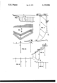
- FIG. 1 is an elevation of the conductor as installed from a distance beneath the surface in deep water, with (a) the conductor, insulator and armorment elements, and (b) the flotation elements, and (c) the tethering/mooring elements. (d) is an illustration variable use of (c) according to requirements.
- FIGS. 2a & 2b are various plan views of deployment schemes. 2b is transversed pattern for additional free movement, as well as surfacing slack on a perdendicular planar method format.
- FIGS. 3a,3b & 3c are variations of elements (b) and (c) in number within a given amount or length of element (a), according to requirements; with (bb) a size variation of element (b).
- FIG. 4 is a one point perspective view of the conductor in full deployment from a point on the sea floor; with (g) being the anchoring element, and (h) being additional tethering elements.
- FIG. 5 is a frontal elevation, with (e) being elongated tether element (c) during surfacing of device from vessel (f). (c) and (h) further indicate in-place scoped multiple tethering.
- the improved conductor elements In order to achieve functional capability, the improved conductor elements must be secured in a combination so as to permit the combined elements of conduction, insulation, armorment, flotation and tethering to achieve apx. specific gravity at the prescribed lateral route and depth of chosen deployment, with sufficient capability for the said means to freely vary within a prescribed variance range radially circumscribing the said routing when the tethering/mooring and anchoring elements are fully deployed in their proper configuration.
- weighting elements might be employed to equalize overbuoyancy.
- the conductor would comprise a central conduction core of copper or aluminum, and would contain oil based fluid or gaseous transfer substances impregnated and/or pressurised in most instances; to provide improved efficiency and thermal discharge ability.
- Surrounding the conduction element is an impregnated paper or a synthetic polymer insulation; the latter being likely in future years as insulation technology for high voltage transmission progresses. Interfacing both conduction and insulation element would be numerous paper, carbon and lead tapes of varying tapes as required for further insulation.
- flotation elements either (A) continuous, or (B) intermittent/segmented deployment depending upon the support configuration deemed proper; especially in order to best maintain proper radial catenary of the combined conduction elements, and particularly the insulation and any internal fluid equilibrium and/or flow.
- flotation elements might be constructed in modular interconnectable format.
- the configuration of the flotation elements would be such as to withstand the depth-pressures of chosen deployment depth, as well as hydrodynamically maintain stable positioning of the device. This configuration is believed best suited to spherical-thru-cylindrical, depending upon application, with minimal tangential contact-for heat dispersion-to conduction elements.
- the size of the said flotation elements would have to vary according to their intermittent use from one another. This factor is further influenced by the number, length and weight of the multiple tethering elements as are employed in combination. The length of the tethers would be determined by depth, as well as line scope factor deemed suitable for a given deployment. The weight would depend upon the type of material used. This most likely would be a polymer synthetic material such as Nylon, Polyester or Kevlar, likely constructed in braided fashion for maximum strength. The flotation elements would likely also be a polymer substance such as syntactic foam for low weight, high strength and long life capacity within deep ocean environmental conditions.
- the conductor In order to achieve sectional surfacing of the conductor it might be either deployed on a transversed lateral plane and sectionally raised from the surface on a perpendicular axis. Additionally, wherein a considerable degree of catanary slack is introduced in the conduction, insulation and armorment elements between segmented flotation elements, the conductor may be surfaced sectionally via elongation of the slack. Also, the servicing may occur in place using proper submersibles.
- elements for securing the principal said elements into a functional entity would naturally be employed where required, as well as means for preserving the proper radial configuration of the conduction, insulation and armoring elements at the point of interconnection with the flotation elements in certain instances; especially in deeply catanaried deployment situations.
- Other means might include electronic sonar signaling devices for subsurface craft warning, as well as surface location access. Also warning devices for excessive depth-pressure operative conditions, as well as automatic shutdown in the event of such conditions should present a hazard to functioning. This might consist of small sensors (affixed to transmission or flotation elements), and a parallel feed circuit therealong.
- a series of slave buoyant means might be temporarily employed for gradual descent from the surface to the depth of desired deployment the deployment vessel moves forward over the chosen route. These means would be strung on successively lengthened tethers astern of the said vessel and cyclically removed and brought forward as the transmission device reaches its proper depth.
- Another potential ancillary means is a tensional flexible member extending between flotation elements in instances where excessive tension upon the conduction, insulation and armorment elements might arise when flotation elements are widely spaced in aforesaid segmented configuration. However, it is unlikely this would be required except under the most severe types of operatonal conditions, or extreme catanaried deployments.
- flotation elements might be either utilised in singular or multiple grouping (in the former instance being of a larger size with multiple conduction, insulation and armorment attachment, or in the latter instance interconnected via proper means to one another).
- the tethering/mooring in such latter instance being attached to one or more said flotation elements as required; according to the number of individual said tether elements deployed at a central apex zone, as well as hydrodynamic stability requirements of a grouped plurality of said flotation elements.
- tethers may be secured directly to said armorment.
- the type of conduction and insulation elements generally referred to herein are the oil impregnated high voltage type developed in 1917, but include also synthetic dialectric type under development, and of any high or ultra high voltage capacity. Though not likely practical, it might through development be possible to incorporate the flotation means within the armorment structure; though heat dissipation problems would likely ensue.
- the conductive elements specifically referred hereto are of depth-pressure sensitive type (with definite maximum depth deployment limitations, and being substantially less than majority intended deep ocean application as suggested herein), as well as being of the ⁇ thermally variable ⁇ single core high voltage self-contained type for submarine use, specifically designed for suspended function (and in most cases individually according to each application).
- the said armorment elements in addition to being applicable to the latter, are designed for integrated use with a required number and configuration of flotation elements (in either said modular interconnectable or independent design format), either in adjacent/tangential (leaving as much of the self-contained transmission elements exposed to the ambient sea for heat cycling and resultant heat dissipation capability; and as distinct from non-thermally active low voltage wires wherein used under similar circumstances), or attached via an intermediate or stringer-type (possibly space frame) interconnection member.
- flotation elements in either said modular interconnectable or independent design format
- adjacent/tangential leaving as much of the self-contained transmission elements exposed to the ambient sea for heat cycling and resultant heat dissipation capability; and as distinct from non-thermally active low voltage wires wherein used under similar circumstances
- intermediate or stringer-type possibly space frame
- Gas Filled (dev. 1955-1965) type is likely to be used for transoceanic-in view of distance-installations; in addition to pressurized or non-pressurized synthetic polymer-at least in part-insulated types, as ongoing capacity developments warrent; including extrusions.
- flotation elements may be integral modules.
- the scoped tethering(s) might also incorporate a length of chain or weighted mechanical tethering at the lower extremity of the line and above the anchoring element. This might help to set the scope in proper configuration.
- deployment computer analysis would likely dictate all aspects of the tethering Array geometry and compositional elements for a given deployment.
- ASW Antisubmarine Warfare
- Such equipment would include ASW hydrophones of various frequency; and various types of additional sensor equipment, such as: current flow indicators, density (salinity/temperature/depth) instrumentation, seismic indicators, sonar and mooring tension indicators, stabilisation detectors and data tape retrieval systems, etc.
- a final structural alternative would entail the use a central interconnection member wherein all, or at least the principal elements of the functional whole would be adaptable thereto (including buoying and/or weighting elements, conductive elements and tethering/mooring lines).
- the configuration of this modular interconnection member may be of space frame or solid type with receiving appartures on its surface. It might be so constructured so as to accept multiple buoyant means in modular format as specific installation requirements dictate, and one or more tethering lines at its underside or lower extremety.
- the said tetherings might be affixed to a universal type joint for freedom of movement in relation to the conductive elements secured thereto.
Landscapes
- Engineering & Computer Science (AREA)
- General Engineering & Computer Science (AREA)
- Mechanical Engineering (AREA)
- Laying Of Electric Cables Or Lines Outside (AREA)
- Insulated Conductors (AREA)
- Cable Accessories (AREA)
Applications Claiming Priority (1)
| Application Number | Priority Date | Filing Date | Title |
|---|---|---|---|
| US60593375A | 1975-08-19 | 1975-08-19 |
Related Parent Applications (1)
| Application Number | Title | Priority Date | Filing Date |
|---|---|---|---|
| US60593375A Continuation-In-Part | 1974-06-19 | 1975-08-19 |
Publications (1)
| Publication Number | Publication Date |
|---|---|
| US4132084A true US4132084A (en) | 1979-01-02 |
Family
ID=24425817
Family Applications (1)
| Application Number | Title | Priority Date | Filing Date |
|---|---|---|---|
| US05/736,737 Expired - Lifetime US4132084A (en) | 1975-08-19 | 1976-10-29 | Submarine conductor for the deep sea transmission of high voltage electrical power |
Country Status (5)
| Country | Link |
|---|---|
| US (1) | US4132084A (enExample) |
| JP (1) | JPS5245078A (enExample) |
| FR (1) | FR2321753A1 (enExample) |
| IT (1) | IT1048460B (enExample) |
| PT (1) | PT65489B (enExample) |
Cited By (16)
| Publication number | Priority date | Publication date | Assignee | Title |
|---|---|---|---|---|
| US4224462A (en) * | 1978-03-21 | 1980-09-23 | Industrie Pirelli S.P.A. | High voltage, electric submarine cable with insulation of longitudinally varying voltage breakdown strength |
| US4388023A (en) * | 1981-04-03 | 1983-06-14 | Hazeltine Corporation | Truss array for supporting devices within a fluid medium |
| US4659253A (en) * | 1985-04-08 | 1987-04-21 | Jacobson Alan R | Deep water cable laying method using buoyancy materials |
| US5120904A (en) * | 1988-05-31 | 1992-06-09 | Permascand Ab | Electrode |
| US6907893B2 (en) * | 2002-04-09 | 2005-06-21 | Bay-B Research And Development Ltd. | Appliance for treating articles, particularly nursing bottles and accessories |
| EP2763144A1 (en) | 2013-02-04 | 2014-08-06 | Nexans | Light weight dynamic subsea power cable |
| US20150325987A1 (en) * | 2014-05-12 | 2015-11-12 | Gwave Llc | Submarine Cable System |
| WO2016188585A1 (de) * | 2015-05-28 | 2016-12-01 | Siemens Aktiengesellschaft | Anordnung zur übertragung von elektrischer energie |
| WO2016188584A1 (de) * | 2015-05-28 | 2016-12-01 | Siemens Aktiengesellschaft | Anordnung zur übertragung von elektrischer energie |
| US20180010713A1 (en) * | 2015-02-24 | 2018-01-11 | Statoil Petroleum As | Pipeline method and apparatus |
| US20180017186A1 (en) | 2015-02-24 | 2018-01-18 | Statoil Petroleum As | Direct tie-in of pipelines by added curvature |
| US9885848B2 (en) * | 2013-07-02 | 2018-02-06 | The Penn State Research Foundation | Composite cable assembly with neutral buoyancy |
| US9944353B2 (en) | 2012-06-04 | 2018-04-17 | Gwave Llc | System for producing energy through the action of waves |
| US9976535B2 (en) | 2005-11-07 | 2018-05-22 | Gwave Llc | System for producing energy through the action of waves |
| CN110415881A (zh) * | 2019-08-21 | 2019-11-05 | 圣安电缆有限公司 | 一种多功能复合岛屿电力电缆及其制造工艺 |
| US20230358336A1 (en) * | 2020-02-24 | 2023-11-09 | Subsea 7 Norway As | Mitigation Of Buckling In Subsea Pipelines |
Citations (7)
| Publication number | Priority date | Publication date | Assignee | Title |
|---|---|---|---|---|
| US2705A (en) * | 1842-07-08 | Improvement in the mode of constructing clasps for pantaloon-straps | ||
| US1711879A (en) * | 1920-12-06 | 1929-05-07 | Cornelius D Ehret | Ship-guiding method and apparatus |
| FR1260389A (fr) * | 1960-06-20 | 1961-05-05 | Dispositif pour le repérage de câbles sous-marins | |
| US3026729A (en) * | 1946-11-04 | 1962-03-27 | Ellis A Johnson | Pressure measuring and recording system |
| US3173271A (en) * | 1960-05-11 | 1965-03-16 | Gerard F Wittgenstein | Underwater pipeline installation |
| US3845233A (en) * | 1973-02-12 | 1974-10-29 | Dielectrics Int Ltd | Pressurized insulant of solid and fluid for a conductor |
| US3858166A (en) * | 1973-12-26 | 1974-12-31 | Briddell C | Recoverable underwater acoustic beacon |
-
1975
- 1975-10-17 IT IT7528374A patent/IT1048460B/it active
-
1976
- 1976-08-17 PT PT65489A patent/PT65489B/pt unknown
- 1976-08-19 JP JP51099189A patent/JPS5245078A/ja active Pending
- 1976-08-19 FR FR7625181A patent/FR2321753A1/fr active Granted
- 1976-10-29 US US05/736,737 patent/US4132084A/en not_active Expired - Lifetime
Patent Citations (7)
| Publication number | Priority date | Publication date | Assignee | Title |
|---|---|---|---|---|
| US2705A (en) * | 1842-07-08 | Improvement in the mode of constructing clasps for pantaloon-straps | ||
| US1711879A (en) * | 1920-12-06 | 1929-05-07 | Cornelius D Ehret | Ship-guiding method and apparatus |
| US3026729A (en) * | 1946-11-04 | 1962-03-27 | Ellis A Johnson | Pressure measuring and recording system |
| US3173271A (en) * | 1960-05-11 | 1965-03-16 | Gerard F Wittgenstein | Underwater pipeline installation |
| FR1260389A (fr) * | 1960-06-20 | 1961-05-05 | Dispositif pour le repérage de câbles sous-marins | |
| US3845233A (en) * | 1973-02-12 | 1974-10-29 | Dielectrics Int Ltd | Pressurized insulant of solid and fluid for a conductor |
| US3858166A (en) * | 1973-12-26 | 1974-12-31 | Briddell C | Recoverable underwater acoustic beacon |
Cited By (19)
| Publication number | Priority date | Publication date | Assignee | Title |
|---|---|---|---|---|
| US4224462A (en) * | 1978-03-21 | 1980-09-23 | Industrie Pirelli S.P.A. | High voltage, electric submarine cable with insulation of longitudinally varying voltage breakdown strength |
| US4388023A (en) * | 1981-04-03 | 1983-06-14 | Hazeltine Corporation | Truss array for supporting devices within a fluid medium |
| US4659253A (en) * | 1985-04-08 | 1987-04-21 | Jacobson Alan R | Deep water cable laying method using buoyancy materials |
| US5120904A (en) * | 1988-05-31 | 1992-06-09 | Permascand Ab | Electrode |
| US6907893B2 (en) * | 2002-04-09 | 2005-06-21 | Bay-B Research And Development Ltd. | Appliance for treating articles, particularly nursing bottles and accessories |
| US9976535B2 (en) | 2005-11-07 | 2018-05-22 | Gwave Llc | System for producing energy through the action of waves |
| US9944353B2 (en) | 2012-06-04 | 2018-04-17 | Gwave Llc | System for producing energy through the action of waves |
| EP2763144A1 (en) | 2013-02-04 | 2014-08-06 | Nexans | Light weight dynamic subsea power cable |
| US9885848B2 (en) * | 2013-07-02 | 2018-02-06 | The Penn State Research Foundation | Composite cable assembly with neutral buoyancy |
| US20150325987A1 (en) * | 2014-05-12 | 2015-11-12 | Gwave Llc | Submarine Cable System |
| US20180010713A1 (en) * | 2015-02-24 | 2018-01-11 | Statoil Petroleum As | Pipeline method and apparatus |
| US20180017186A1 (en) | 2015-02-24 | 2018-01-18 | Statoil Petroleum As | Direct tie-in of pipelines by added curvature |
| US10520112B2 (en) * | 2015-02-24 | 2019-12-31 | Statoil Petroleum As | Pipeline method and apparatus |
| US10571048B2 (en) | 2015-02-24 | 2020-02-25 | Statoil Petroleum As | Direct tie-in of pipelines by added curvature |
| WO2016188585A1 (de) * | 2015-05-28 | 2016-12-01 | Siemens Aktiengesellschaft | Anordnung zur übertragung von elektrischer energie |
| WO2016188584A1 (de) * | 2015-05-28 | 2016-12-01 | Siemens Aktiengesellschaft | Anordnung zur übertragung von elektrischer energie |
| CN110415881A (zh) * | 2019-08-21 | 2019-11-05 | 圣安电缆有限公司 | 一种多功能复合岛屿电力电缆及其制造工艺 |
| US20230358336A1 (en) * | 2020-02-24 | 2023-11-09 | Subsea 7 Norway As | Mitigation Of Buckling In Subsea Pipelines |
| US12398827B2 (en) * | 2020-02-24 | 2025-08-26 | Subsea 7 Norway As | Mitigation of buckling in subsea pipelines |
Also Published As
| Publication number | Publication date |
|---|---|
| FR2321753A1 (fr) | 1977-03-18 |
| IT1048460B (it) | 1980-11-20 |
| JPS5245078A (en) | 1977-04-08 |
| PT65489A (fr) | 1976-09-01 |
| PT65489B (fr) | 1978-03-27 |
| FR2321753B1 (enExample) | 1981-05-22 |
Similar Documents
| Publication | Publication Date | Title |
|---|---|---|
| US4132084A (en) | Submarine conductor for the deep sea transmission of high voltage electrical power | |
| KR101531321B1 (ko) | 계류식 해양환경 관측부이 | |
| KR101841594B1 (ko) | 방수기능이 구비된 부력식 해양 관측 장치 | |
| US8758072B2 (en) | Marine device | |
| US4391332A (en) | Offshore facility for recovery hydrocarbon deposits from deep sea beds | |
| US3794849A (en) | Power transmission system for connecting floating power plant to stationary conductors | |
| NO20120590A1 (no) | System og fremgangsmate for en marin undersokelse ved bruk av vertikalt orienterte sensorstreamere | |
| EP3645864B1 (en) | Wave powered generator | |
| KR102361654B1 (ko) | 안정성이 향상된 해양표층관측 관측시스템 | |
| US4274757A (en) | Immersion/suspension method for the submarine deployment of high voltage transmission cable | |
| NO119459B (enExample) | ||
| KR102052014B1 (ko) | 다기능 위치추적체 | |
| US3728748A (en) | Mooring apparatus | |
| Zhang et al. | Design and optimization of buoy mooring with single-point cable for seafloor observatories | |
| Frye et al. | Mooring developments for autonomous ocean-sampling networks | |
| MY136211A (en) | A device for handling of cables on seismic vessels | |
| Zhang et al. | Prototype system design of mooring buoy for seafloor observation and construction of its communication link | |
| CN210572777U (zh) | 一种基于光纤水听器的海洋地震勘探垂直缆系统 | |
| CN109061746A (zh) | 一种卫星传输海洋磁力探测装置 | |
| USRE23552E (en) | Apparatus for marine seismic prospecting | |
| CA1077280A (en) | Submarine conductor for deep sea transmission of high voltage electrical power | |
| CN121312058A (zh) | 可潜式太阳能装置 | |
| Richardson | Drifters and floats | |
| Wood et al. | A compliant surface mooring system for real-time data acquisition | |
| Teng et al. | A compact wave and ocean data buoy system |