US4063843A - Adjustable boring bar - Google Patents
Adjustable boring bar Download PDFInfo
- Publication number
- US4063843A US4063843A US05/697,846 US69784676A US4063843A US 4063843 A US4063843 A US 4063843A US 69784676 A US69784676 A US 69784676A US 4063843 A US4063843 A US 4063843A
- Authority
- US
- United States
- Prior art keywords
- members
- telescopically engaged
- boring bar
- end portion
- shank
- Prior art date
- Legal status (The legal status is an assumption and is not a legal conclusion. Google has not performed a legal analysis and makes no representation as to the accuracy of the status listed.)
- Expired - Lifetime
Links
Images
Classifications
-
- B—PERFORMING OPERATIONS; TRANSPORTING
- B23—MACHINE TOOLS; METAL-WORKING NOT OTHERWISE PROVIDED FOR
- B23B—TURNING; BORING
- B23B31/00—Chucks; Expansion mandrels; Adaptations thereof for remote control
- B23B31/02—Chucks
- B23B31/028—Chucks the axial positioning of the tool being adjustable
-
- Y—GENERAL TAGGING OF NEW TECHNOLOGICAL DEVELOPMENTS; GENERAL TAGGING OF CROSS-SECTIONAL TECHNOLOGIES SPANNING OVER SEVERAL SECTIONS OF THE IPC; TECHNICAL SUBJECTS COVERED BY FORMER USPC CROSS-REFERENCE ART COLLECTIONS [XRACs] AND DIGESTS
- Y10—TECHNICAL SUBJECTS COVERED BY FORMER USPC
- Y10T—TECHNICAL SUBJECTS COVERED BY FORMER US CLASSIFICATION
- Y10T408/00—Cutting by use of rotating axially moving tool
- Y10T408/83—Tool-support with means to move Tool relative to tool-support
-
- Y—GENERAL TAGGING OF NEW TECHNOLOGICAL DEVELOPMENTS; GENERAL TAGGING OF CROSS-SECTIONAL TECHNOLOGIES SPANNING OVER SEVERAL SECTIONS OF THE IPC; TECHNICAL SUBJECTS COVERED BY FORMER USPC CROSS-REFERENCE ART COLLECTIONS [XRACs] AND DIGESTS
- Y10—TECHNICAL SUBJECTS COVERED BY FORMER USPC
- Y10T—TECHNICAL SUBJECTS COVERED BY FORMER US CLASSIFICATION
- Y10T408/00—Cutting by use of rotating axially moving tool
- Y10T408/89—Tool or Tool with support
- Y10T408/907—Tool or Tool with support including detailed shank
Definitions
- Boring bars that are used with numerically controlled tape machines are of the detachable nature having an insert holding portion on one end and a collar type attachment on the other such that the boring bars may be attached to turrets and the like and used upon a tape controlled cutting machine.
- the tape controlled cutting machine usually has a referenced datum dimension when measured from some control point on the tape controlled machine spindle to the end point where the cutting insert will perform upon the workpiece.
- the head of the boring bar is a replaceable item such that different cutting configurations and cutting tools may be interchanged on the boring bar to provide the desired end result on the workpiece.
- the boring bars also use cemented hard metal carbide inserts which are, themselves, indexable and, also, interchangeable such that inserts, themselves, may be changed at some point during the cutting operation when the cutting insert becomes dull.
- a shank for a boring bar which comprises first and second members having end portions telescopically engaged with each other with said first and second members being held in nonrotatable relationship relative to each other.
- An axial adjustable abutment ring is mounted on one of said first and second members, such as by thread means, with the ring having an abutment face to abut a portion of the member other than which it is mounted. Rotation of the abutment ring advances the ring axially along the length of the member upon which it is mounted and provides a locating stop for the member against which the face of the abutment ring abuts.
- the member upon which the abutment ring is mounted preferably has the innermost telescopically engaged portion and a recess is formed in the outer surface of the innermost telescopically engaged member such that the recess has a declining surface in the direction of the abutment ring.
- a clamp element preferably, a threaded cone point set screw, is mounted in the outermost telescopically engaged member and is operable to be moved radially inward so that it engages the declining surface and urges one of said first and second members into firm abutment with the abutment ring.
- Means for holding said first and second members in a nonrotatable relationship of one to the other comprising various configurations comprising a pin element engaged with the outer and inner telescopically engaged members such that the inner telescopically engaged member is slidable axially inside the outer member with the pin element engaged between the two members holding the two members nonrotatable relative to each other.
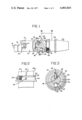
- FIG. 1 is a partially cut-away side view of a boring bar according to the present invention.
- FIG. 2 is a view through section II--II of FIG. 1.
- FIG. 3 is a view through section III--III of FIG. 1.
- FIG. 4 is a modification of the arrangement shown in FIG. 1.
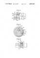
- FIG. 5 is a further modification of the arrangement shown in FIG. 1.
- FIG. 6 is a modification of the adjustable abutment ring shown in FIG. 2.
- FIG. 1 a boring bar 10 having on one end a detachable head element 12 having a portion thereon for seating a cutting insert 14.
- the detachable cutting head 12 is held on the bar by bolt 16 which extends downward through the body of the bar 10 and also an extension 18 of the detachable head 12.
- This type of connection has been found to be very satisfactory and is further described in applicants own U.S. Pat. Nos. 3,704,958, 3,765,788, 3,801,213 and 3,856,428, assigned to Kennametal Inc.
- a spindle adaptor 20 On the opposite end of the boring bar 10 from the detachable head 12 is a spindle adaptor 20 which is adapted for attachment to a machining center, such as a turret and the like, usually found on numerically controlled tape machines. Part of the spindle adaptor 20 is formed by a tapered diameter 22 which will abut into the turret as mentioned above and provide a reference point from the abutment diameter to the foremost edge of the cutting insert 14. This reference dimension is programmed into the tape of the computer operated machine such that precise and accurate cutting tolerances may be maintained.
- the boring bar 10 has a detachable cutting head 12 and also a removable cutting insert 14 such that, when either one or both have been replaced, the referenced dimension from tapered diameter 22 to the cutting point of cutting insert 14 may be changed somewhat, and it is, therefore, preferable to have an adjustment mechanism in the body of the boring bar 10 such that the operator may reset the cutting point of cutting insert 14 to the known referenced dimension on the tape.
- FIG. 1 Shown in FIG. 1 is boring bar 10 having a first member 20 and a second member 24, respectively, having telescopically engaged end portions 26 and 28.
- End portion 26 of first member 20 forms the innermost telescopically engaged portion and is preferably cylindrical in cross section and has a close sliding fit inside bore 30 formed in end portion 28 of second member 24.
- An abutment ring 32 is mounted on first member 20, preferably by thread means 34, such that, when abutment ring 32 is rotated, it may advance or retreat along the axial length of the first member 20.
- Abutment ring 32 has a face 36 which faces the end portion 28 of second member 24 and abuts with the corresponding face 38 on the end portion 28.
- the innermost telescopically engaged end portion 26 has a recess 40 formed in its outer periphery such that there is a declining surface 42 which declines in a direction toward the abutment ring 32.
- a clamp screw 44 is threadedly engaged through the end portion 28 such that it is operable upon rotation to advance radially inwardly and engage the declining surface 42 of end portion 26 so that the abutting faces 38 of first member 24 and the abutment surface 36 of abutment ring 32 are urged into a solid rigid contact. Threaded clamp member 44, of course, is only operated into engagement with declining surface 42 when the abutment ring 32 has been set at the predetermined axial location.
- First member 20 and second member 24 of boring bar 10 are held in a nonrotatable relation one to the other by engagement with dowel pin 46.
- Dowel pin 46 is press fitted into a hole 48 formed in end portion 28 and extends upwardly into a longitudinal groove 50 which is formed in end portion 26 of first member 20. Dowel pin 46 thus allows first member 20 and second member 24 to have axial movement relative to one another while also preventing rotational movement from one to the other.
- FIG. 2 what is shown therein is a view II--II through FIG. 1.
- the first member 20 of boring bar 10 having mounted thereon the adjustable abutment ring 32.
- the adjustable abutment ring 32 is mounted on the first member 20 by threaded means 34 such that rotation of the ring 32 will move it axially along the length of the first member 20 depending on the direction of rotation chosen.
- Calibrated markings 52 are shown on surface 54 of ring 32.
- Surface 54 of ring 32 is frusto-conically shaped with respect to the main body of ring 32 such that the surface recesses inwardly to mate with an indicator marked 56 which is located upon the end portion 28 of a second member 24.
- the calibrated markings 52 are correlated with the pitch of the threads 54 such that a division between each markings 52 represents an axial movement of ring 32 along first member 20 designated in thousandths of an inch.
- a clamp screw 58 may be adjusted downwardly through ring 32 so as to firmly engage the threads 34 and hold the ring 32 nonrotatable with first member 20.
- FIG. 3 what is shown therein is a boring bar 10 with end portions 28 and 26 telescopically engaged and having an extremely close sliding fit as shown in FIG. 3.
- Ring member 32 is shown mounted on first member 20 and having its calibrated markings 52 showing markings completely around a side face of the ring member 32.
- Clamp member 44 is shown in its clamped position down in the recess 40 and on the declining surface 42 such that the second member 24 is urged into abutment with the abutment ring 32.
- Groove 30 can be seen more clearly in FIG. 3 as it engages the dowel pin member 46 which, in turn, has a press fit with the hole 48.
- the groove 30 and end portion 26 which engage the dowel pin 46 located in hole 48 of the second end portion 28 allows first member 20 and second member 24 to have relative axial movement with one another while being prevented from having a rotational movement relative to one another.
- FIG. 4 what is shown therein is again the boring bar 10 having telescopically engaged end portions 26 and 28 with the same arrangement of clamp screw 44 in recess 40 as has been described above. Shown in FIG. 4, however, is a modified arrangement of a structure to prevent relative rotational movement between end portions 26 and 28 while allowing relative axial movement between first member 20 and second member 24.
- FIG. 4 Shown in FIG. 4 is a longitudinal bore 60 formed extending inwardly of end portion 26 and, similarly, a longitudinal bore 62 is formed extending inwardly from bore 30 and second member 24.
- a pin member 64 is engaged between longitudinal bores 60 and 62 such that relative axial movement can be had between first member 20 and second member 24 while relative rotational movement is provided.
- Pin member 64 may be press fitted in either of longitudinal bores 60 or 62 as long as the other bore 60 or 62 is provided with some clearance for the pin to slide therein.
- FIG. 5 What is shown in FIG. 5 is again end portions 26 and 28 having the same clamp screw 44 in recess 40 as has been described above. However, a third construction for holding the first and second members nonrotational relative to one another is shown therein.
- a transverse hole 66 is formed through end portion 28 such that another pin member 68 is press fitted into transverse hole 66.
- End portion 26 now has been formed such that a longitudinal flat may be located along one side thereof such that it engages the pin member 68 and is thereby held in a nonrotative relationship with end portion 28.
- the flat itself, being longitudinal, allows axial motion between end portions 26 and 28.
- FIG. 6 what is shown therein is a more detailed view of the clamp screw 58 having a threaded connection with ring member 32. Also shown herein is ring member 32 having a modified threaded engagement 70 with the first member 20 wherein the crown of the threads terminate in flats which is much more aptly described as acme threads.
- acme threads An advantage of the acme threads over any other threading arrangement is that, when clamp screw 58 is operated radially inwardly to engage said threads 70, the threads will not be damaged by such clamping action.
- a plastic member 72 may be interposed between the clamp bolt 58 and the thread 70 such that thread 70 will not be damaged if clamp screw 58 is overtorqued during operation.
Landscapes
- Engineering & Computer Science (AREA)
- Mechanical Engineering (AREA)
- Cutting Tools, Boring Holders, And Turrets (AREA)
- Drilling Tools (AREA)
- Earth Drilling (AREA)
Priority Applications (5)
| Application Number | Priority Date | Filing Date | Title |
|---|---|---|---|
| US05/697,846 US4063843A (en) | 1976-06-21 | 1976-06-21 | Adjustable boring bar |
| CA280,649A CA1085192A (en) | 1976-06-21 | 1977-06-16 | Adjustable boring bar |
| GB25785/77A GB1541530A (en) | 1976-06-21 | 1977-06-21 | Adjustable boring bar |
| FR7719025A FR2355600A1 (fr) | 1976-06-21 | 1977-06-21 | Barre d'alesage reglable |
| DE2727838A DE2727838C3 (de) | 1976-06-21 | 1977-06-21 | Bohrstange |
Applications Claiming Priority (1)
| Application Number | Priority Date | Filing Date | Title |
|---|---|---|---|
| US05/697,846 US4063843A (en) | 1976-06-21 | 1976-06-21 | Adjustable boring bar |
Publications (1)
| Publication Number | Publication Date |
|---|---|
| US4063843A true US4063843A (en) | 1977-12-20 |
Family
ID=24802819
Family Applications (1)
| Application Number | Title | Priority Date | Filing Date |
|---|---|---|---|
| US05/697,846 Expired - Lifetime US4063843A (en) | 1976-06-21 | 1976-06-21 | Adjustable boring bar |
Country Status (5)
| Country | Link |
|---|---|
| US (1) | US4063843A (sv) |
| CA (1) | CA1085192A (sv) |
| DE (1) | DE2727838C3 (sv) |
| FR (1) | FR2355600A1 (sv) |
| GB (1) | GB1541530A (sv) |
Cited By (15)
| Publication number | Priority date | Publication date | Assignee | Title |
|---|---|---|---|---|
| DE3108439C1 (de) * | 1981-03-06 | 1982-11-04 | Komet Stahlhalter- Und Werkzeugfabrik Robert Breuning Gmbh, 7122 Besigheim | Bohrwerkzeug, insbesondere Bohrstange |
| US4486130A (en) * | 1981-09-12 | 1984-12-04 | Willi Lipp | Rotary tool with tool positioning adjustment |
| US4507027A (en) * | 1982-07-12 | 1985-03-26 | Thomas Adamson | Adjustable boring head tool holder |
| US4575292A (en) * | 1984-02-24 | 1986-03-11 | Heinz Kaiser A.G. | Device for connecting a tool part to a connecting shaft |
| US4761102A (en) * | 1986-01-16 | 1988-08-02 | Emile Pfalzgraf | Drilling head with jointly or individually radially adjustable tools |
| US4813831A (en) * | 1987-03-11 | 1989-03-21 | Gottlieb Guhring Kg | Coupling system for cutting shank tools |
| EP0405443A1 (en) * | 1989-06-26 | 1991-01-02 | Mitsubishi Materials Corporation | Boring bar tool |
| US5040932A (en) * | 1989-12-04 | 1991-08-20 | Kennametal Inc. | Locator mechanism for a tool holder assembly |
| US5261767A (en) * | 1989-06-26 | 1993-11-16 | Mitsubishi Metal Corporation | Boring bar tool |
| US5341710A (en) * | 1985-01-02 | 1994-08-30 | J. P. Tool, Inc. | Coupling structure and method |
| US20030133764A1 (en) * | 2002-01-16 | 2003-07-17 | Erickson Robert A. | Adjustment device for self-colleting drill motors |
| US20050115293A1 (en) * | 2003-11-28 | 2005-06-02 | Goh Thiam H. | Thread rolling tool |
| US20080279645A1 (en) * | 2007-05-09 | 2008-11-13 | Taegutec Ltd. | Tool assembly |
| US20100247256A1 (en) * | 2009-03-30 | 2010-09-30 | The Boeing Company | Boring Bar Apparatus |
| US9505059B2 (en) * | 2014-10-14 | 2016-11-29 | X'pole Precision Tools Inc. | Tools holder |
Families Citing this family (5)
| Publication number | Priority date | Publication date | Assignee | Title |
|---|---|---|---|---|
| US4877360A (en) * | 1985-05-07 | 1989-10-31 | Emile Pfalzgraf | Apparatus for locking and/or gripping modular attachments of boring heads, boring bars, intermediate members, adapters, tool holders, hydraulic punches, long tongs, or other mechanical members |
| FR2669849A1 (fr) * | 1990-11-30 | 1992-06-05 | Coc Carbure Outils Coupants | Dispositif de fixation et d'orientation d'un outil coupant dans un adaptateur, lui-meme oriente dans une broche de machines-outils. |
| DE4212709C2 (de) * | 1992-04-16 | 1997-04-17 | Hans Esslinger | Werkzeug mit einem austauschbaren, einen zylindrischen Schaft aufweisenden Schneidkörper für die spanabhebende Formgebung, vornehmlich in der Metallbearbeitung |
| US5468102A (en) * | 1994-09-02 | 1995-11-21 | Stojanovski; Stojan | Milling tool holder |
| FR2935917B1 (fr) | 2008-09-12 | 2011-08-26 | E P B | Porte-outil a reglage axial |
Citations (4)
| Publication number | Priority date | Publication date | Assignee | Title |
|---|---|---|---|---|
| US2089930A (en) * | 1935-07-03 | 1937-08-10 | Raymond A Carlson | Machine tool spindle construction |
| US3202433A (en) * | 1964-02-24 | 1965-08-24 | Davis Arthur George | Adapter with adjustment for setting cutters |
| US3316615A (en) * | 1965-04-30 | 1967-05-02 | O K Tool Co Inc | Machine tool |
| US3444781A (en) * | 1967-10-19 | 1969-05-20 | Sonnet Tool & Mfg Co | Tool holder |
-
1976
- 1976-06-21 US US05/697,846 patent/US4063843A/en not_active Expired - Lifetime
-
1977
- 1977-06-16 CA CA280,649A patent/CA1085192A/en not_active Expired
- 1977-06-21 GB GB25785/77A patent/GB1541530A/en not_active Expired
- 1977-06-21 FR FR7719025A patent/FR2355600A1/fr active Granted
- 1977-06-21 DE DE2727838A patent/DE2727838C3/de not_active Expired
Patent Citations (4)
| Publication number | Priority date | Publication date | Assignee | Title |
|---|---|---|---|---|
| US2089930A (en) * | 1935-07-03 | 1937-08-10 | Raymond A Carlson | Machine tool spindle construction |
| US3202433A (en) * | 1964-02-24 | 1965-08-24 | Davis Arthur George | Adapter with adjustment for setting cutters |
| US3316615A (en) * | 1965-04-30 | 1967-05-02 | O K Tool Co Inc | Machine tool |
| US3444781A (en) * | 1967-10-19 | 1969-05-20 | Sonnet Tool & Mfg Co | Tool holder |
Cited By (18)
| Publication number | Priority date | Publication date | Assignee | Title |
|---|---|---|---|---|
| DE3108439C1 (de) * | 1981-03-06 | 1982-11-04 | Komet Stahlhalter- Und Werkzeugfabrik Robert Breuning Gmbh, 7122 Besigheim | Bohrwerkzeug, insbesondere Bohrstange |
| US4486130A (en) * | 1981-09-12 | 1984-12-04 | Willi Lipp | Rotary tool with tool positioning adjustment |
| US4507027A (en) * | 1982-07-12 | 1985-03-26 | Thomas Adamson | Adjustable boring head tool holder |
| US4575292A (en) * | 1984-02-24 | 1986-03-11 | Heinz Kaiser A.G. | Device for connecting a tool part to a connecting shaft |
| US5341710A (en) * | 1985-01-02 | 1994-08-30 | J. P. Tool, Inc. | Coupling structure and method |
| US4761102A (en) * | 1986-01-16 | 1988-08-02 | Emile Pfalzgraf | Drilling head with jointly or individually radially adjustable tools |
| US4813831A (en) * | 1987-03-11 | 1989-03-21 | Gottlieb Guhring Kg | Coupling system for cutting shank tools |
| US5261767A (en) * | 1989-06-26 | 1993-11-16 | Mitsubishi Metal Corporation | Boring bar tool |
| EP0405443A1 (en) * | 1989-06-26 | 1991-01-02 | Mitsubishi Materials Corporation | Boring bar tool |
| US5040932A (en) * | 1989-12-04 | 1991-08-20 | Kennametal Inc. | Locator mechanism for a tool holder assembly |
| US20030133764A1 (en) * | 2002-01-16 | 2003-07-17 | Erickson Robert A. | Adjustment device for self-colleting drill motors |
| US6913427B2 (en) | 2002-01-16 | 2005-07-05 | Kennametal Inc. | Adjustment device for self-colleting drill motors |
| US20050115293A1 (en) * | 2003-11-28 | 2005-06-02 | Goh Thiam H. | Thread rolling tool |
| US20080279645A1 (en) * | 2007-05-09 | 2008-11-13 | Taegutec Ltd. | Tool assembly |
| US7520704B2 (en) * | 2007-05-09 | 2009-04-21 | Taegutec Ltd. | Tool Assembly |
| US20100247256A1 (en) * | 2009-03-30 | 2010-09-30 | The Boeing Company | Boring Bar Apparatus |
| US8360693B2 (en) * | 2009-03-30 | 2013-01-29 | The Boeing Company | Boring bar apparatus |
| US9505059B2 (en) * | 2014-10-14 | 2016-11-29 | X'pole Precision Tools Inc. | Tools holder |
Also Published As
| Publication number | Publication date |
|---|---|
| DE2727838C3 (de) | 1980-12-11 |
| FR2355600A1 (fr) | 1978-01-20 |
| CA1085192A (en) | 1980-09-09 |
| DE2727838B2 (de) | 1980-04-17 |
| GB1541530A (en) | 1979-03-07 |
| FR2355600B1 (sv) | 1982-11-19 |
| DE2727838A1 (de) | 1977-12-22 |
Similar Documents
| Publication | Publication Date | Title |
|---|---|---|
| US4063843A (en) | Adjustable boring bar | |
| US4575293A (en) | Machine tool holder having opposed ramp members | |
| US4579488A (en) | Boring bar assembly | |
| CA2134404C (en) | Milling tool holder | |
| US3289273A (en) | Cutting tool assembly | |
| US3397615A (en) | Tool arbor | |
| US3635572A (en) | Boring bar adjustment | |
| US2368736A (en) | Turret toolholder | |
| US3918826A (en) | Boring tool having retractable cartridge | |
| US3363299A (en) | Cutting tool assembly | |
| US4097181A (en) | Rotary cutting tool | |
| US2684249A (en) | Toolhead and taper shank adapter | |
| DE1237404B (de) | Bohrkopf | |
| US2849902A (en) | Presetting boring bar and tool holder | |
| US2282919A (en) | Boring bar | |
| US2891429A (en) | Bearing pocket boring tool | |
| US3313187A (en) | Boring bar insert | |
| US5066173A (en) | Aluminum piston wrist pin boring tool | |
| US3228267A (en) | Combination centering and facing tool | |
| US5288182A (en) | Boring bar holder and insert with precision placement insert locator means | |
| US2629270A (en) | Boring bar micrometer tool | |
| US3738767A (en) | Adjustable boring bar | |
| US4063842A (en) | Adjustable boring bar | |
| US4544309A (en) | Adjustable cutting or boring tool | |
| US3246545A (en) | Working tool |