US4061053A - Vehicle service brake pedal - Google Patents
Vehicle service brake pedal Download PDFInfo
- Publication number
- US4061053A US4061053A US05/607,179 US60717975A US4061053A US 4061053 A US4061053 A US 4061053A US 60717975 A US60717975 A US 60717975A US 4061053 A US4061053 A US 4061053A
- Authority
- US
- United States
- Prior art keywords
- pedal
- brake
- released position
- vehicle
- operator
- Prior art date
- Legal status (The legal status is an assumption and is not a legal conclusion. Google has not performed a legal analysis and makes no representation as to the accuracy of the status listed.)
- Expired - Lifetime
Links
- 239000003351 stiffener Substances 0.000 description 4
- 230000000717 retained effect Effects 0.000 description 3
- 208000004067 Flatfoot Diseases 0.000 description 1
- 230000008030 elimination Effects 0.000 description 1
- 238000003379 elimination reaction Methods 0.000 description 1
- 239000000463 material Substances 0.000 description 1
- 238000000034 method Methods 0.000 description 1
Images


Classifications
-
- G—PHYSICS
- G05—CONTROLLING; REGULATING
- G05G—CONTROL DEVICES OR SYSTEMS INSOFAR AS CHARACTERISED BY MECHANICAL FEATURES ONLY
- G05G1/00—Controlling members, e.g. knobs or handles; Assemblies or arrangements thereof; Indicating position of controlling members
- G05G1/30—Controlling members actuated by foot
- G05G1/46—Means, e.g. links, for connecting the pedal to the controlled unit
-
- B—PERFORMING OPERATIONS; TRANSPORTING
- B60—VEHICLES IN GENERAL
- B60T—VEHICLE BRAKE CONTROL SYSTEMS OR PARTS THEREOF; BRAKE CONTROL SYSTEMS OR PARTS THEREOF, IN GENERAL; ARRANGEMENT OF BRAKING ELEMENTS ON VEHICLES IN GENERAL; PORTABLE DEVICES FOR PREVENTING UNWANTED MOVEMENT OF VEHICLES; VEHICLE MODIFICATIONS TO FACILITATE COOLING OF BRAKES
- B60T7/00—Brake-action initiating means
- B60T7/02—Brake-action initiating means for personal initiation
- B60T7/04—Brake-action initiating means for personal initiation foot actuated
-
- Y—GENERAL TAGGING OF NEW TECHNOLOGICAL DEVELOPMENTS; GENERAL TAGGING OF CROSS-SECTIONAL TECHNOLOGIES SPANNING OVER SEVERAL SECTIONS OF THE IPC; TECHNICAL SUBJECTS COVERED BY FORMER USPC CROSS-REFERENCE ART COLLECTIONS [XRACs] AND DIGESTS
- Y10—TECHNICAL SUBJECTS COVERED BY FORMER USPC
- Y10T—TECHNICAL SUBJECTS COVERED BY FORMER US CLASSIFICATION
- Y10T74/00—Machine element or mechanism
- Y10T74/20—Control lever and linkage systems
- Y10T74/20528—Foot operated
-
- Y—GENERAL TAGGING OF NEW TECHNOLOGICAL DEVELOPMENTS; GENERAL TAGGING OF CROSS-SECTIONAL TECHNOLOGIES SPANNING OVER SEVERAL SECTIONS OF THE IPC; TECHNICAL SUBJECTS COVERED BY FORMER USPC CROSS-REFERENCE ART COLLECTIONS [XRACs] AND DIGESTS
- Y10—TECHNICAL SUBJECTS COVERED BY FORMER USPC
- Y10T—TECHNICAL SUBJECTS COVERED BY FORMER US CLASSIFICATION
- Y10T74/00—Machine element or mechanism
- Y10T74/20—Control lever and linkage systems
- Y10T74/20576—Elements
- Y10T74/20888—Pedals
Definitions
- This invention relates generally to material handling vehicles, and more specifically to a service brake system for a vehicle which is controlled by an operator in a standing position.
- the braking force is necessarily provided by a spring, effectively taking away some of the operator's control of the braking force applied.
- the service brake pedal When the service brake pedal is pushed down to apply the brake, the operator must either stand with both feet to one side of the vehicle on the parking brake pedal, or with one foot raised over the raised service brake pedal in position to operate the brake as required. Either way, it is difficult under normal operating conditions for the operator to stand in a normal manner with his feet spread comfortably apart, and with his weight comfortably distributed on both feet.
- the service and parking brakes must be interconnected so that the hydraulic pressure in the service brake system is released when the mechanical parking brake is applied.
- a dumping valve must be introduced into the system to relieve pressure in the service brake system when the parking brakes are applied, and to allow the service brake system to be repressurized every time the vehicle is reoccupied. It can be appreciated that elimination of such a valve is desirable from the standpoint of both cost and reliability.
- an object of the present invention is to provide a service brake system for a stand-up industrial vehicle which permits the operator to assume a comfortable and normal stance during all phases of vehicle operation.
- Another object of the invention is to provide a service brake system in which the actuating pedal is pressed downward to apply the service brake.
- Another object of the invention is to provide a service brake in which braking force is controlled entirely by the operator.
- Another object of the invention is to provide a service brake which minimizes the time required for an operator to move his foot into position to operate the brake.
- the present invention takes advantage of the fact that on the average, a person in a normal standing position has approximately 60% of his weight on his heels, and 40% on the balls of his feet.
- the invention provides a brake pedal and associated linkage which is normally in a level attitude and which remains level when stood upon in a normal manner, the rear portion of the pedal corresponding to the operator's heel being supported by a suitable stop.
- the pedal linkage permits the forward portion of the pedal to depress downward below a level attitude. Through suitable linkage this depression is caused to actuate the operating rod of a conventional hydraulic master cylinder.
- the pedal linkage is arranged so that a definite forward and downward pressure must be applied by the ball of the operator's foot in order to move the pedal from its level attitude and operate the brake.
- Field tests have shown that there is little liklihood of inadvertent brake actuation and once an operator becomes accustomed to not being required to lift his foot as part of the brake application process, it has been found to be a highly practical system.
- the pedal linkage comprises a pair of links, both of which are located forward of the point where the operator's heel will rest on the pedal.
- the links are angled away from each other from their attachment to the frame of the vehicle and an operator's normal weight distribution tends to tilt the pedal backward against a stop to maintain a relatively level attitude of the pedal.
- the rear link moves toward an over center position and the forward link moves toward a horizontal position such that essentially the full weight of the operator can be put into braking force applied to a master cylinder linkage.
- FIG. 1 is a rear perspective view of the operator's station of an industrial vehicle incorporating the invention
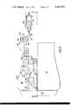
- FIG. 2 is a partial plan view, with parts of the vehicle removed for clarity, showing the pedal structure of the invention
- FIG. 3 is a side elevation view of the service brake pedal and brake linkage in its normal position
- FIG. 4 is a view similar to FIG. 3, but showing the service brake pedal and brake linkage in its brake applied position.
- FIG. 1 there is illustrated the operator's station of a typical stand-up type industrial vehicle, designated generally by the numeral 10. Included at the operator's station are a tiller 12 for steering wheels 14 of the vehicle, a control handle 16 for controlling vehicle travel and for controlling lifting and lowering of a load carriage (not shown) of the vehicle, a control handle 18 for tilting of the load carriage, a parking brake pedal 20, and a service brake pedal 22.
- the parking brake system is not important to the present invention and will not be described in detail.
- the parking brake pedal 20 is shown in its normal position for an unattended vehicle.
- the pedal is mechanically connected to wheel brakes in a conventional manner, and is pivotally mounted to the vehicle frame, with the rearward end spring-loaded in an up position, corresponding to the actuated condition of the parking brakes.
- an operator gets on the vehicle, he steps on the parking brake pedal, releasing the parking brakes through a suitable linkage.
- it can be assumed that the parking brake system is completely independent of the service brake system.
- the service brake pedal 22 is part of a service brake system, which is shown in more detail in FIGS. 2, 3 and 4, and designated generally by the numeral 24.
- the service brake pedal 22 normally rests in a level position, generally corresponding to the down position of the parking brake pedal 20, thus forming a flat, level surface for the operator to stand on.
- a fixed plate 26 extending across the rear of both pedals can be added to further provide a stable base for the operator.
- the service brake system 24 essentially comprises the pedal 22, first and second link members 28, 30 supporting the pedal on a section 46 of the vehicle frame, a master cylinder 32, and actuating lever arms 34 and 35, linking the pedal to the master cylinder for actuation of the service brakes.
- the master cylinder operates in a conventional manner to apply braking force signals to the vehicle's hydraulic service brakes.
- the service brake pedal 22 comprises a flat foot plate 36, a pair of longitudinal stiffeners 38, 40 welded or otherwise fastened to the underside of the footplate, and a toe plate 42 welded or otherwise fastened to the top of the foot plate 36.
- the toe plate 42 is a U-shaped member which is intended to insure that the toe of an operator's shoe will be retained on the pedal, as shown in FIG. 2, when the service brake is actuated, as will be described in more detail later.
- each of the links 28 and 30 is pivotally mounted between a pair of brackets 44 (one of two shown), which are welded or otherwise fastened to the frame 46.
- the pivot pins 48, 50, respectively, which mount the links to the brackets can be retained by any conventional means, such as by press fitting into the brackets, or by retaining rings.
- the opposite ends of the links 28, 30 are similarly pivotally mounted between the stiffeners 38, 40, by means of pivot pins 52, 54 respectively.
- upper pivot pin 52 of the link 28 is disposed somewhat rearwardly of lower pin 48
- upper pin 54 of link 30 is disposed somewhat forwardly of lower pin 50 when the pedal is in its brake released position.
- the forward link 30 is somewhat longer than rearward link 28, and at a greater angle to the vertical.
- FIG. 2 the outline of a typical shoe 55 is shown in broken lines over the pedal 22. It can be appreciated that over a wide range of shoe sizes, the heel of the shoe will rest behind pivot pin 52.
- the arrow W in FIG. 3 represents the resultant of half the operator's weight. So long as the operator's weight on his one foot is applied to the region over or behind the pin 52, the effective force on the pedal 22 will cause it to tilt rearwardly. Accordingly, a stop 56 is provided which contacts a pad 58 welded or otherwise fastened across the underside of the stiffeners 38, 40.
- the stop 56 is in the form of a bolt 60, which is threaded through a portion of the vehicle frame 46 and locked in place by means of a locknut 62. As shown, the stop 56 is adjusted to maintain the pedal 22 in a slightly backwardtilted attitude under normal, non-braking conditions, although it can be appreciated that the stop 56 can be adjusted to set the rear end of pedal 22 somewhat above or below a level attitude.
- the service brake system master cylinder 32 is bolted to a vertical bracket plate 64, which is welded or otherwise fastened to a convenient part of the vehicle frame.
- the lever arm 34 is pinned at its forward end to a pivot rod 66, which is supported for rotation by bearing members 68, 70 welded or otherwise fastened to a convenient vehicle frame member.
- the rod 66 is retained longitudinally by means of snap rings 72.
- lever arm 35 is also pinned to the pivot rod 66, thus forming a bellcrank in cooperation with lever arm 34, and is connected at its free end to the actuating rod 76 of master cylinder 32 by means of a pin 78, which can be pivotally received in either or both of the lever arm 35 or the actuating rod 76.
- the lever arm 34 is disposed so that its rearward end underlies a portion of the foot plate 36 of pedal 22.
- a relatively large diameter pin 80 is welded or otherwise rigidly fastened to the arm 34, and has a generally horizontally oriented stub end portion in position to contact a curved cam plate 82 fastened to one side of the stiffener 38. The contact between pin 80 and cam plate 82 occurs approximately beneath the ball of the operator's foot during braking.
- a return spring 84 received in a cylindrical retainer 86 attached to a portion of the frame 46 is engageable with a lateral extension 88 of the actuating rod 34 to set the normal, unbraked, position of the service brake pedal 22, in conjuction with the stop 56.
- the toe plate 42 further serves to permit full brake actuation force to be applied to the master cylinder 32 without danger of the operator's foot slipping off the pedal 22.
Landscapes
- Engineering & Computer Science (AREA)
- Physics & Mathematics (AREA)
- General Physics & Mathematics (AREA)
- Automation & Control Theory (AREA)
- Transportation (AREA)
- Mechanical Engineering (AREA)
- Braking Elements And Transmission Devices (AREA)
Priority Applications (4)
| Application Number | Priority Date | Filing Date | Title |
|---|---|---|---|
| US05/607,179 US4061053A (en) | 1975-08-25 | 1975-08-25 | Vehicle service brake pedal |
| GB32097/76A GB1522093A (en) | 1975-08-25 | 1976-08-02 | Apparatus for vehicle service brake |
| CA258,723A CA1076978A (en) | 1975-08-25 | 1976-08-09 | Vehicle service brake pedal |
| FR7625477A FR2322029A1 (fr) | 1975-08-25 | 1976-08-23 | Pedale de frein a pied pour vehicule |
Applications Claiming Priority (1)
| Application Number | Priority Date | Filing Date | Title |
|---|---|---|---|
| US05/607,179 US4061053A (en) | 1975-08-25 | 1975-08-25 | Vehicle service brake pedal |
Publications (1)
| Publication Number | Publication Date |
|---|---|
| US4061053A true US4061053A (en) | 1977-12-06 |
Family
ID=24431158
Family Applications (1)
| Application Number | Title | Priority Date | Filing Date |
|---|---|---|---|
| US05/607,179 Expired - Lifetime US4061053A (en) | 1975-08-25 | 1975-08-25 | Vehicle service brake pedal |
Country Status (4)
| Country | Link |
|---|---|
| US (1) | US4061053A (OSRAM) |
| CA (1) | CA1076978A (OSRAM) |
| FR (1) | FR2322029A1 (OSRAM) |
| GB (1) | GB1522093A (OSRAM) |
Cited By (6)
| Publication number | Priority date | Publication date | Assignee | Title |
|---|---|---|---|---|
| US4336860A (en) * | 1980-01-24 | 1982-06-29 | The Prime-Mover Co. | Material handling vehicle having improved deadman control |
| WO1996024519A1 (en) * | 1995-02-10 | 1996-08-15 | Crown Equipment Corporation | Isolated floor for material handling vehicle |
| EP0752354A1 (de) * | 1995-07-01 | 1997-01-08 | Dr.Ing.h.c. F. Porsche Aktiengesellschaft | Bremsbetätigungseinrichtung für ein Flurförderfahrzeug |
| US8616603B2 (en) | 2010-04-23 | 2013-12-31 | The Raymond Corporation | Operator ride enhancement system |
| US20210309189A1 (en) * | 2020-04-07 | 2021-10-07 | Excel Industries, Inc. | Parking brake system for stand-on terrain working vehicle |
| US20240426373A1 (en) * | 2023-06-22 | 2024-12-26 | Ayro, Inc. | Interlocking bellcrank device and associated systems and methods |
Citations (6)
| Publication number | Priority date | Publication date | Assignee | Title |
|---|---|---|---|---|
| US2042202A (en) * | 1934-03-20 | 1936-05-26 | Arthur B Althouse | Automobile control device |
| US2131972A (en) * | 1936-09-21 | 1938-10-04 | John W Ruhstorfer | Brake and accelerator control |
| US2281755A (en) * | 1940-11-05 | 1942-05-05 | Edgar C Dunning | Combined accelerator and brake |
| US2542410A (en) * | 1947-03-07 | 1951-02-20 | Tabor Mfg Co | Motor vehicle control mechanism |
| US2620050A (en) * | 1949-04-14 | 1952-12-02 | Menard Paul | Single pedal for brakes and accelerators |
| US3481216A (en) * | 1967-11-13 | 1969-12-02 | Emilio L Noriega | Air brake pedal |
-
1975
- 1975-08-25 US US05/607,179 patent/US4061053A/en not_active Expired - Lifetime
-
1976
- 1976-08-02 GB GB32097/76A patent/GB1522093A/en not_active Expired
- 1976-08-09 CA CA258,723A patent/CA1076978A/en not_active Expired
- 1976-08-23 FR FR7625477A patent/FR2322029A1/fr active Granted
Patent Citations (6)
| Publication number | Priority date | Publication date | Assignee | Title |
|---|---|---|---|---|
| US2042202A (en) * | 1934-03-20 | 1936-05-26 | Arthur B Althouse | Automobile control device |
| US2131972A (en) * | 1936-09-21 | 1938-10-04 | John W Ruhstorfer | Brake and accelerator control |
| US2281755A (en) * | 1940-11-05 | 1942-05-05 | Edgar C Dunning | Combined accelerator and brake |
| US2542410A (en) * | 1947-03-07 | 1951-02-20 | Tabor Mfg Co | Motor vehicle control mechanism |
| US2620050A (en) * | 1949-04-14 | 1952-12-02 | Menard Paul | Single pedal for brakes and accelerators |
| US3481216A (en) * | 1967-11-13 | 1969-12-02 | Emilio L Noriega | Air brake pedal |
Cited By (10)
| Publication number | Priority date | Publication date | Assignee | Title |
|---|---|---|---|---|
| US4336860A (en) * | 1980-01-24 | 1982-06-29 | The Prime-Mover Co. | Material handling vehicle having improved deadman control |
| WO1996024519A1 (en) * | 1995-02-10 | 1996-08-15 | Crown Equipment Corporation | Isolated floor for material handling vehicle |
| US5579859A (en) * | 1995-02-10 | 1996-12-03 | Crown Equipment Corporation | Isolated floor for material handling vehicle |
| EP0752354A1 (de) * | 1995-07-01 | 1997-01-08 | Dr.Ing.h.c. F. Porsche Aktiengesellschaft | Bremsbetätigungseinrichtung für ein Flurförderfahrzeug |
| US5746291A (en) * | 1995-07-01 | 1998-05-05 | Dr. Ing. H.C.F. Porsche Ag | Floor conveyor vehicle |
| US8616603B2 (en) | 2010-04-23 | 2013-12-31 | The Raymond Corporation | Operator ride enhancement system |
| US20210309189A1 (en) * | 2020-04-07 | 2021-10-07 | Excel Industries, Inc. | Parking brake system for stand-on terrain working vehicle |
| US11498532B2 (en) * | 2020-04-07 | 2022-11-15 | Excel Industries, Inc. | Parking brake system for stand-on terrain working vehicle |
| US12024144B2 (en) | 2020-04-07 | 2024-07-02 | Excel Industries, Inc. | Parking brake system for stand-on terrain working vehicle |
| US20240426373A1 (en) * | 2023-06-22 | 2024-12-26 | Ayro, Inc. | Interlocking bellcrank device and associated systems and methods |
Also Published As
| Publication number | Publication date |
|---|---|
| CA1076978A (en) | 1980-05-06 |
| GB1522093A (en) | 1978-08-23 |
| FR2322029A1 (fr) | 1977-03-25 |
| FR2322029B3 (OSRAM) | 1979-05-18 |
Similar Documents
| Publication | Publication Date | Title |
|---|---|---|
| US4320818A (en) | Wheelchair brake assembly | |
| US4088334A (en) | Skateboard brake | |
| US4683977A (en) | Adjustable pedal assembly | |
| US5579859A (en) | Isolated floor for material handling vehicle | |
| US3006593A (en) | Multiple position seat | |
| JP2667221B2 (ja) | 飛行機用トラクター | |
| US3385608A (en) | Skateboard brake | |
| US4061053A (en) | Vehicle service brake pedal | |
| US4204588A (en) | Wheelchair braking apparatus | |
| US3941399A (en) | Barrel carrier | |
| KR100517690B1 (ko) | 유압식 지게 카트 | |
| US5524731A (en) | Universally mountable brake assembly for a hand truck | |
| GB2243198A (en) | Wheel stopping device for baby carriages | |
| US5036959A (en) | Wheelchair with a braking assembly | |
| US3664454A (en) | Deadman seat actuated brake | |
| US5623855A (en) | Motorcycle parking stand | |
| US2259924A (en) | Braking means for invalid chairs | |
| US20030164269A1 (en) | An all-terrain board with leg operated brake | |
| US2722847A (en) | Pedal structure for automotive vehicles | |
| US3987871A (en) | Trolley cart braking system | |
| US3836160A (en) | Stair ascending or descending cart | |
| US3664453A (en) | Deadman seat actuated brake and handbrake construction | |
| US2856195A (en) | Hand truck | |
| US4119327A (en) | Lever for motorcycle center stand | |
| US6116621A (en) | Roller skate swing brake |
Legal Events
| Date | Code | Title | Description |
|---|---|---|---|
| AS | Assignment |
Owner name: YALE MATERIALS HANDLING CORPORATION ROUTE 523 AND Free format text: ASSIGNMENT OF ASSIGNORS INTEREST.;ASSIGNOR:EATON CORPORATION;REEL/FRAME:004261/0903 Effective date: 19831231 |
|
| AS | Assignment |
Owner name: CITICORP NORTH AMERICA, INC., AS AGENT Free format text: SECURITY INTEREST;ASSIGNOR:YALE MATERIALS HANDLING CORPORATION;REEL/FRAME:005228/0113 Effective date: 19890526 |