US4052627A - Ultrasonic ceramic microphone - Google Patents
Ultrasonic ceramic microphone Download PDFInfo
- Publication number
- US4052627A US4052627A US05/674,239 US67423976A US4052627A US 4052627 A US4052627 A US 4052627A US 67423976 A US67423976 A US 67423976A US 4052627 A US4052627 A US 4052627A
- Authority
- US
- United States
- Prior art keywords
- microphone
- metal plate
- diameter
- thickness
- ultrasonic
- Prior art date
- Legal status (The legal status is an assumption and is not a legal conclusion. Google has not performed a legal analysis and makes no representation as to the accuracy of the status listed.)
- Expired - Lifetime
Links
Images


Classifications
-
- H—ELECTRICITY
- H04—ELECTRIC COMMUNICATION TECHNIQUE
- H04R—LOUDSPEAKERS, MICROPHONES, GRAMOPHONE PICK-UPS OR LIKE ACOUSTIC ELECTROMECHANICAL TRANSDUCERS; DEAF-AID SETS; PUBLIC ADDRESS SYSTEMS
- H04R17/00—Piezoelectric transducers; Electrostrictive transducers
- H04R17/02—Microphones
-
- B—PERFORMING OPERATIONS; TRANSPORTING
- B06—GENERATING OR TRANSMITTING MECHANICAL VIBRATIONS IN GENERAL
- B06B—METHODS OR APPARATUS FOR GENERATING OR TRANSMITTING MECHANICAL VIBRATIONS OF INFRASONIC, SONIC, OR ULTRASONIC FREQUENCY, e.g. FOR PERFORMING MECHANICAL WORK IN GENERAL
- B06B1/00—Methods or apparatus for generating mechanical vibrations of infrasonic, sonic, or ultrasonic frequency
- B06B1/02—Methods or apparatus for generating mechanical vibrations of infrasonic, sonic, or ultrasonic frequency making use of electrical energy
- B06B1/06—Methods or apparatus for generating mechanical vibrations of infrasonic, sonic, or ultrasonic frequency making use of electrical energy operating with piezoelectric effect or with electrostriction
- B06B1/0603—Methods or apparatus for generating mechanical vibrations of infrasonic, sonic, or ultrasonic frequency making use of electrical energy operating with piezoelectric effect or with electrostriction using a piezoelectric bender, e.g. bimorph
Definitions
- the present invention relates to an ultrasonic ceramic microphone having a wide operating frequency range.
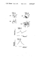
- An ultrasonic ceramic microphone (hereinafter referred to as a microphone) using an electro-acoustic transducer (hereinafter referred to as a transducer) generally comprises, as shown in FIGS. 1(a) and 1(b) a metal plate 1 sandwiched by piezoelectric ceramic plates 2 and 3, and leads 4 and 5 connected to the piezoelectric ceramic plates 2 and 3, respectively to complete a transducer 6, which is, in turn, housed in a casing 8 having an opening 7 on one side as shown in FIGS. 2(a) and 2(b).
- the piezoelectric ceramic plates 2 and 3 are provided with electrodes on upper and lower surfaces thereof, and the polarizations of the piezoelectric ceramic plates 2 and 3 are in opposite sense to each other.
- FIG. 3 shows the admittance-frequency characteristic of the transducer 6
- FIG. 4 shows the receiving sensitivity-frequency characteristic thereof.
- a microphone 15 thus constructed is used for reception, if the frequency of an incoming sound wave coincides with the resonance frequency of the transducer 6, a voltage at that frequency appears across the electrodes of the transducer 6. This represents the receiving sensitivity.
- an electric signal of the frequency equal to the resonance frequency of the transducer 6 is applied across the electrodes, the transducer 6 mechanically vibrates to produce a sound wave at that frequency. This constitutes a transmitting sound wave.
- Such a type of microphone 15 has been widely used in a remote control device for a television receiver set, air conditioning apparatus, electric fan or automatic door of a garage, a sensor for a burglar-proof system, and a sensor for a proximity switch or range finder.
- the prior art microphone 15 could not satisfactorily comply with such wishes. Accordingly, in order to overcome the above drawback and provide a wide operating range microphone, various approaches have been tried. In one method, for example, a metal plate was divided into a plurality of segments to present several resonance frequencies.
- an object of the present invention to provide a microphone which overcomes the disadvantages encountered in the prior art systems and is capable of broadening the band more than ten kHz compared with the prior system, and yet is easy to manufacture and very useful in industrial application.
- FIGS. 1(a) and (b) show the construction of a commonly used electro-accoustic transducer
- FIGS. 2(a) and (b) show the construction of an ultrasonic ceramic microphone using the electro-accoustic transducer of FIGS. 1(a) and (b).
- FIG. 3 shows the admittance characteristic of a prior art microphone.
- FIG. 4 shows the reception characteristic of a prior art microphone.
- FIGS. 5(a) and (b) show the admittance characteristic and the receiving sensitivity characteristic of a prior art wide band microphone
- FIGS. 6(a) and (b) show the admittance characteristic and the receiving sensitivity characteristic of another prior art wide band microphone
- FIG. 7 shows the fundamental wave and first, second and third order harmonics with respect to the diameter of an aluminum plate having a thickness of 0.1 mm, with piezoelectric ceramic plates of 8.2 mm in diameter and 0.26 in thickness being used.
- FIG. 8 shows an admittance characteristic in accordance with the present invention.
- FIG. 9 shows the receiving sensitivity characteristic of a microphone of the present invention.
- FIG. 10 shows the sound pressure level characteristic of a microphone of the present invention.
- FIGS. 11 to 14 show the relationship between the diameters of aluminum plates and the resonance frequencies for various thickness and diameters of piezoelectric ceramic plates.
- FIG. 15 summerizes FIGS. 11 to 14 showing the relation of t/(R/2) 2 cm -1 between the diameter R and the thickness t of the aluminum plate.
- FIG. 16 is a graphic representation of FIG. 15.
- the microphone of the present invention is similar in construction to that shown in FIGS. 1 and 2 but is characterized in that it is operated near two or three adjacent resonance frequencies and in a frequency band covering those resonance frequencies, of a fundamental wave and respective order higher harmonics of the deflection vibration of a transducer.
- the transducer has first, second and third harmonic vibration modes. Generally the transducer does not always have an infinite number of harmonic vibration modes but has one to four at most. For example, for a given thickness and diameter of the piezoelectric ceramic plates and a given thickness of the aluminum sandwiched thereby, only a fundamental wave is generated when the diameter of the aluminum plate is small, and as the diameter of the aluminum plate increases the fundamental wave attenuates and the second, third and fourth harmonics are generated. The frequencies of the harmonics are multiples of the frequency given by the equation (1) by the factor of the constants.
- the resonance frequency thereof is approximately proportional to the thickness and inversely proportional to the square of the diameter, although it cannot be said that Q and ⁇ are not at all dependent on the diameters and thickness of the respective elements.
- the resonance frequency in order to form a wide band microphone it is necessary to have a resonance frequency at f o + (10 to 15) kHz and f o - (10 to 15) kHz about a center frequency f o kHz.
- FIG. 7 shows the change of the resonance frequency with respect to the diameter of the aluminum plate when the piezoelectric ceramic plates have diameter of 8.2 mm, and a thickness of 0.26 mm and the aluminum plate has a thickness of 0.1 mm.
- curve 19 is for a fundamental wave
- curve 20 is for a first harmonic
- curve 21 is for a second harmonic
- curve 22 is for a third harmonic.
- the resonance frequencies appear near 30 kHz and 50 kHz.
- the addmitance characteristic of the transducer is shown in FIG. 8, the receiving sensitivity characteristic of a microphone using the above transducer is shown in FIG. 9, and the transmission sound pressure characteristic is shown in FIG. 10. It is seen from those figures that the microphone has an operating frequency band of 20 kHz wide or more, which is three times as wide as that of the prior art microphone. In FIGS. 9 and 10, curves 23 show the characteristics in accordance with the present invention.
- FIG. 11 shows the relationship between the diameter of the aluminum plate and the resonance frequencies for fundamental wave (A 1 ), first harmonic (A 2 ), second harmonic (A 3 ), third harmonic (A 4 ) and fourth harmonic (A 5 ), in an ultrasonic ceramic microphone having an aluminum plate of 0.1 mm thickness as the metal plate 1 shown in FIG. 1 and piezoelectric ceramic plates of 0.26 mm thickness and 6.0 mm diameter disposed on the upper and lower surfaces of the aluminum plate.
- FIGS. 12 to 14 show the relations of the diameter of the aluminum plate to the resonance frequencies for the fundamental wave (A 1 ), first harmonic (A 2 ), second harmonic (A 3 ), third harmonic (A 4 ), . . .
- an ultrasonic ceramic microphone having an aluminum plate of 0.1 mm thickness and piezoelectric ceramic plates of 0.3 mm thickness and 6.0 mm diameter (FIG. 12)
- an ultrasonic ceramic microphone having an aluminum plate of 0.1 mm thickness and piezoelectric ceramic plates of 0.2 mm thickness and 8.2 mm diameter (FIG. 13)
- an ultrasonic ceramic microphone having an aluminum plate of 0.1 mm thickness and piezoelectric ceramic plates of 0.30 thickness and 8.2 mm diameter (FIG. 14), respectively.
- FIG. 15 summarizes FIGS. 11 to 14 showing the value of ##EQU2## where R is the diameter of the aluminum plate and t is the thickness thereof.
- FIG. 16 is a graphic representation of FIG. 15, in which a first harmonic appears near 30 kHz when the condition of ##EQU3## is met and thus a wide band ultrasonic ceramic microphone can be provided.
- the present invention can provide a wide band microphone in a simple and easy way.
Landscapes
- Engineering & Computer Science (AREA)
- Mechanical Engineering (AREA)
- Physics & Mathematics (AREA)
- Acoustics & Sound (AREA)
- Signal Processing (AREA)
- Transducers For Ultrasonic Waves (AREA)
- Piezo-Electric Transducers For Audible Bands (AREA)
Applications Claiming Priority (2)
| Application Number | Priority Date | Filing Date | Title |
|---|---|---|---|
| JP50044559A JPS51118984A (en) | 1975-04-11 | 1975-04-11 | Supersonic ceramic microphone |
| JA50-44559 | 1975-04-11 |
Publications (1)
| Publication Number | Publication Date |
|---|---|
| US4052627A true US4052627A (en) | 1977-10-04 |
Family
ID=12694844
Family Applications (1)
| Application Number | Title | Priority Date | Filing Date |
|---|---|---|---|
| US05/674,239 Expired - Lifetime US4052627A (en) | 1975-04-11 | 1976-04-06 | Ultrasonic ceramic microphone |
Country Status (6)
| Country | Link |
|---|---|
| US (1) | US4052627A (OSRAM) |
| JP (1) | JPS51118984A (OSRAM) |
| DE (1) | DE2615593C3 (OSRAM) |
| FR (1) | FR2307427A1 (OSRAM) |
| GB (1) | GB1548962A (OSRAM) |
| NL (1) | NL167572C (OSRAM) |
Cited By (4)
| Publication number | Priority date | Publication date | Assignee | Title |
|---|---|---|---|---|
| US4367426A (en) * | 1980-03-19 | 1983-01-04 | Hitachi, Ltd. | Ceramic transparent piezoelectric transducer |
| US4368400A (en) * | 1979-05-15 | 1983-01-11 | Yoshiharu Taniguchi | Piezoelectric ultrasonic transducer mounted in a housing |
| CN1036108C (zh) * | 1994-07-22 | 1997-10-08 | 王志坚 | 传声器 |
| US20040144552A1 (en) * | 2000-03-16 | 2004-07-29 | Makita Corporation | Power tools |
Families Citing this family (5)
| Publication number | Priority date | Publication date | Assignee | Title |
|---|---|---|---|---|
| JPS5667731A (en) | 1979-11-06 | 1981-06-08 | Nissan Motor Co Ltd | Knocking sensor |
| DE3029067C2 (de) * | 1980-07-31 | 1982-07-01 | Bolta-Werke Gmbh, 8561 Diepersdorf | Vorrichtung zur Schallerzeugung, insbesondere für Weck- oder Alarmeinrichtungen |
| JPS5939198A (ja) * | 1982-08-27 | 1984-03-03 | Victor Co Of Japan Ltd | マイクロホン装置 |
| DE3318525A1 (de) * | 1982-09-30 | 1984-04-05 | Emhart Industries, Inc., 46206 Indianapolis, Ind. | Ton-signalgebereinrichtung |
| FR2536622B1 (fr) * | 1982-11-19 | 1986-03-07 | Thomson Csf | Hydrophone de vitesse |
Family Cites Families (1)
| Publication number | Priority date | Publication date | Assignee | Title |
|---|---|---|---|---|
| JPS50123329A (OSRAM) * | 1974-03-14 | 1975-09-27 |
-
1975
- 1975-04-11 JP JP50044559A patent/JPS51118984A/ja active Pending
-
1976
- 1976-04-06 US US05/674,239 patent/US4052627A/en not_active Expired - Lifetime
- 1976-04-08 GB GB14403/76A patent/GB1548962A/en not_active Expired
- 1976-04-09 DE DE2615593A patent/DE2615593C3/de not_active Expired
- 1976-04-09 NL NL7603763.A patent/NL167572C/xx not_active IP Right Cessation
- 1976-04-09 FR FR7610460A patent/FR2307427A1/fr active Granted
Cited By (5)
| Publication number | Priority date | Publication date | Assignee | Title |
|---|---|---|---|---|
| US4368400A (en) * | 1979-05-15 | 1983-01-11 | Yoshiharu Taniguchi | Piezoelectric ultrasonic transducer mounted in a housing |
| US4367426A (en) * | 1980-03-19 | 1983-01-04 | Hitachi, Ltd. | Ceramic transparent piezoelectric transducer |
| CN1036108C (zh) * | 1994-07-22 | 1997-10-08 | 王志坚 | 传声器 |
| US20040144552A1 (en) * | 2000-03-16 | 2004-07-29 | Makita Corporation | Power tools |
| US7036605B2 (en) * | 2000-03-16 | 2006-05-02 | Makita Corporation | Power tools |
Also Published As
| Publication number | Publication date |
|---|---|
| AU1279776A (en) | 1977-10-27 |
| NL7603763A (nl) | 1976-10-13 |
| FR2307427B1 (OSRAM) | 1980-10-17 |
| NL167572B (nl) | 1981-07-16 |
| DE2615593C3 (de) | 1978-10-12 |
| NL167572C (nl) | 1981-12-16 |
| DE2615593B2 (de) | 1978-02-16 |
| GB1548962A (en) | 1979-07-18 |
| DE2615593A1 (de) | 1976-10-21 |
| FR2307427A1 (fr) | 1976-11-05 |
| JPS51118984A (en) | 1976-10-19 |
Similar Documents
| Publication | Publication Date | Title |
|---|---|---|
| US2967957A (en) | Electroacoustic transducer | |
| US4653606A (en) | Electroacoustic device with broad frequency range directional response | |
| CA1183937A (en) | Piezoelectric transducer apparatus | |
| US4485321A (en) | Broad bandwidth composite transducers | |
| JP3123431B2 (ja) | 圧電スピーカ | |
| US4228379A (en) | Diaphragm type piezoelectric electroacoustic transducer | |
| US4297538A (en) | Resonant electroacoustic transducer with increased band width response | |
| US4052627A (en) | Ultrasonic ceramic microphone | |
| US3849679A (en) | Electroacoustic transducer with controlled beam pattern | |
| GB1254037A (en) | Ultrasonic transducer employing suspended piezoelectric plate | |
| US5103482A (en) | Apparatus and method for reproducing high fidelity sound | |
| US3675053A (en) | Ultrasonic wave microphone | |
| WO1989005445A1 (en) | An acoustic emission transducer and an electrical oscillator | |
| US3058539A (en) | Transducer with impedance-matching bridge | |
| US4845776A (en) | Piezoelectric transducer and transformer circuit | |
| US3749854A (en) | Ultrasonic wave microphone | |
| US4037181A (en) | Acoustic surface wave filter devices | |
| US3253674A (en) | Ceramic microphone | |
| CA1065047A (en) | Ultrasonic ceramic microphone | |
| US3671784A (en) | Piezo-electric transducers having variable sensitivity between the boundaries of the piezo-electric crystal | |
| EP0353092A2 (en) | Apparatus and method for reproducing high fidelity sound | |
| US3749855A (en) | Resistive electrode for an electrostrictive transducer | |
| JPS635354Y2 (OSRAM) | ||
| Sear et al. | Noise-cancelling microphone using a piezoelectric plastics transducing element | |
| US2908772A (en) | Electroacoustical transducer |