US4046200A - Lawn edger attachment - Google Patents
Lawn edger attachment Download PDFInfo
- Publication number
- US4046200A US4046200A US05/626,032 US62603275A US4046200A US 4046200 A US4046200 A US 4046200A US 62603275 A US62603275 A US 62603275A US 4046200 A US4046200 A US 4046200A
- Authority
- US
- United States
- Prior art keywords
- arm
- coulter
- blade
- coulter arm
- broom
- Prior art date
- Legal status (The legal status is an assumption and is not a legal conclusion. Google has not performed a legal analysis and makes no representation as to the accuracy of the status listed.)
- Expired - Lifetime
Links
Images
Classifications
-
- A—HUMAN NECESSITIES
- A01—AGRICULTURE; FORESTRY; ANIMAL HUSBANDRY; HUNTING; TRAPPING; FISHING
- A01G—HORTICULTURE; CULTIVATION OF VEGETABLES, FLOWERS, RICE, FRUIT, VINES, HOPS OR SEAWEED; FORESTRY; WATERING
- A01G3/00—Cutting implements specially adapted for horticultural purposes; Delimbing standing trees
- A01G3/06—Hand-held edge trimmers or shears for lawns
- A01G3/062—Motor-driven edge trimmers
-
- A—HUMAN NECESSITIES
- A01—AGRICULTURE; FORESTRY; ANIMAL HUSBANDRY; HUNTING; TRAPPING; FISHING
- A01D—HARVESTING; MOWING
- A01D34/00—Mowers; Mowing apparatus of harvesters
- A01D34/835—Mowers; Mowing apparatus of harvesters specially adapted for particular purposes
- A01D34/84—Mowers; Mowing apparatus of harvesters specially adapted for particular purposes for edges of lawns or fields, e.g. for mowing close to trees or walls
Definitions
- This invention relates to new and useful improvements in lawn edgers, that is, devices for cutting the grass of lawns which tends to extend out over the surface of adjacent sidewalks, driveways and the like, and which cannot be cut by ordinary mowers.
- Various devices for this purpose have heretofore been proposed, but all within our knowledge have been subject to certain disadvantages. They have been generally complicated, cumbersome, and difficult to operate. If mounted on self-propelled vehicles, they have required very careful and precise steering of the vehicle to keep the edging blade positioned accurately at the edge of the concrete. If mounted on any type of manually propelled carrier, they have tended to require excessive manual force for operation.
- the general object of the present invention accordingly, is the provision of a lawn edging device which overcomes all of the above enumerated disadvantages of prior devices.
- a lawn edging device consisting of a rolling coulter blade carried for rotation on a horizontal axis generaly transverse to the line of travel at the rearward end of a coulter arm, the coulter arm being pivoted at its forward end on a generally vertical axis to a self-propelled vehicle, whereby the blade trails the pivotal axis of the arm, and can move transversely to the line of travel.
- Manual means are provided for pivoting the arm, whereby the blade may be guided to follow the pavement edge accurately despite variations in the spacing of the vehicle from said edge.
- Another object is the provision of a lawn edger of the character described wherein are provided means for pivoting the coulter arm vertically, whereby the blade may be elevated entirely above ground level for convenience of transport, and means resiliently resisting lateral pivoting of the coulter arm, so as to resist unrestrained swinging of said arm when it is in its transport position.
- a further object is the provision of a lawn edger of the character described including means whereby the normal trailing angle of the coulter arm may be adjusted. If properly used as a guide for spacing the carrying vehicle from the pavement edge, this provides a degree of automatic "self-steering" of the blade, as well as “self-sharpening” thereof against the pavement.
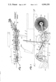
- FIG. 1 is a side elevational view of a lawn edging device embodying the present invention, shown operativey mounted as an attachment for a mowing machine, indicated in dotted lines,
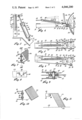
- FIG. 2 is a fragmentary sectional view taken on line II--II of FIG. 1,
- FIG. 3 is an enlarged, fragmentary sectional view taken on line III--III of FIG. 2,
- FIG. 4 is an enlarged, fragmentary sectional view taken on line IV--IV of FIG. 2, showing the spring-release position of the spring lever in dotted lines,
- FIG. 5 is a top plan view of the parts shown in FIG. 4,
- FIG. 6 is a view similar to FIG. 5, showing the spring adjusted to change the trailing angle of the coulter arm
- FIG. 7 is an enlarged, fragmentary sectional view taken on line VII--VII of FIG. 1,
- FIG. 8 is a fragmentary sectional view taken on line VIII--VIII of FIG. 7,
- FIG. 9 is an enlarged, fragmentary sectional view taken on line IX--IX of FIG. 1,
- FIG. 10 is a view similar to FIG. 7, but showing a scraper blade substituted for the sweeper broom, and
- FIG. 11 is a side elevational view of the parts shown in FIG. 10.
- Said mowing machine includes a small self-propelled tractor 4 having powered ground-engaging wheels 6 (one shown), adapted to move forwardly to the left, as viewed in FIGS. 1 and 2. It may also have a rear castered wheel, not shown. It also includes a driver's seat 8 and control levers 10. Attached to the forward end of the tractor is a mowing head 12 which it will be understood includes mower blades powered by the tractor, and which is supported by castered ground-engaging wheels 14 (one shown). Said head includes a hood member 16 which projects laterally to the left of the tractor body. The present lawn-edger, indicated generally by the numeral 18, is mounted on this leftward projection of hood 16.
- the edger device includes a bracket 20 rigidly affixed to the top surface of hood 16 by any suitable means, not shown. Pivoted to said bracket on a horizontal transverse axis, as by bolt 22, is a generally upright mounting plate 24 to which is welded an upright stub axle 26 which projects upwardly from said plate. Mounted rotatably on said stub axle is a sleeve 28 to which is rigidly affixed a downwardly and rearwardly inclined coulter arm 30, said arm consisting of a pair of laterally spaced apart side rails 32. A collar 34 is rigidly affixed on axle 26 above sleeve 28 to secure said sleeve on said axle.
- a hydraulic ram 36 includes a double-acting hydraulic cylinder 38 having hydraulic connections 40 and 42, and a piston 44 operable in said cylinder and having affixed thereto a piston rod 46 projecting axially from the cylinder.
- the extended end of said piston rod is pivoted, as at 48, between a pair of ears 50 affixed to collar 34.
- the ram is inclined downwardly and forwardly from pivot 48, and the lower end of cylinder 38 is pivoted, as at 52, to bracket 20.
- axle 26 may be pivoted on bolt 22 to respectively lower or raise coulter arm 30 in a vertical direction.
- the hydraulic control system for ram 36 may be standard and is not shown, it being understood that this system is powered by a hydraulic pump mounted on and driven by tractor 4, and is operable to maintain a constant pressure in cylinder 38 when desired. Also affixed to collar 34 is a rigid spring connector arm 54 which is inclined downwardly and rearwardly in spaced apart relation above coulter arm 30, but which is much shorter than said coulter arm.
- blade protector 66 is affixed to said cross bar by bolts 68 (see FIG. 4) and curves upwardly and rearwardly around said blade to protect operators against injury by said blade.
- a spring tightener lever 70 is mounted between said rails 32 of arm 30.
- Said lever consists of a pair of lever arms 72 disposed slidably against the inner sides of rails 32, and pivoted adjacent their forward ends to rails 32 by coaxial bolts 74, and a plate 76 extending laterally between and rigidly affixed to the rearward ends of said lever arms.
- the lever is normally secured in this position by a retainer bolt 78 extending through rails 32 and the rearward end portions of lever arms 72.
- a series of laterally spaced apart holes 80 are formed in the forward edge portion of plate 76, and a similar series of holes 82 are formed in the rearward end of arm 54 affixed to collar 34.
- a helical tension spring 84 has its forward end hooked selectively into any one of holes 82, and its rearward end hooked selectivey into any one of holes 80. When hooked into the central holes, as in FIG. 5, said spring tends to hold coulter arm 30 yieldably in a position trailing directly rearwardly from stub axle 26, since lateral pivoting of said arm in either direction will be resisted by the extension of said spring.
- said spring When said spring is hooked into others of holes 80 and 82, as in FIG. 6, it will yieldably position arm 30 at positions at either side of a vertical plane extending directly rearwardly from axle 26, the direction of offset from said plane, and the degree of offset, being determined as desired by the holes 80 and 82 selected.
- lever 70 When retainer bolt 78 is removed, lever 70 may be pivoted upwardly and forwardly on bolts 74, as indicated in dotted lines in FIG. 4. This relaxes spring 84, so that its ends may be easily unhooked from holes 80 and 82 and reinserted in others of said holes as desired, after which lever 70 may be pivoted rearwardly and downwardly to its original position and secured by retainer bolt 78.
- a steering handle 86 which normally projects upwardly to a position adjacent the tractor driver occupying seat 8, in order that he may guide arm 30 laterally, against the resistance of spring 84, in order to maintain blade 56 against the edge of the pavement.
- Said handle also serves as a rigid extension of lever 70, whereby, during adjustments of said spring as already described, said lever may be pivoted easily against the tension of the spring.
- a U-shaped broom carrier 92 Pivoted to side rails 32 of arm 30, just rearwardly of cross bar 64, by means of transversely coaxial bolts 88, are the parallel side arms 90 of a U-shaped broom carrier 92. Said carrier extends rearwardly of blade 56, and its rearward connecting portion 94 (see FIG. 7) has affixed thereto by bolts 96 the forward connecting portion 98 of an angled U-shaped broom bracket 100, the parallel side arms 102 of which extend rearwardly at a horizontally lateral angle, as best shown in FIG. 2.
- a circular broom 106 mounted rotatably between side arms 102, on a transverse axis represented by bolt 104, is a circular broom 106.
- Said broom rests freely on the ground surface therebeneath because of its pivotal support by bolts 88, and is turned by its contact with said ground surface as mowing machine 2 moves forwardly, providing a transverse sweeping action by reason on its horizontally angular relation to the direction of travel.
- the holes 108 of bracket 100 through which its mounting bolts 96 pass are slotted to engage said bolts only loosely. This permits said bracket to be adjusted so that the peripheral face of the broom may rest flush on the ground surface.
- a scraper blade 110 may be secured to pivoted carrier 92 by bolts 96, as shown in FIGS. 10 and 11.
- Said scraper blade is formed of sheet metal, and its lower edge 112 rests on ground surface 114 by gravity in the same manner as broom 106, said edge being horizontally sloped relative to the direction of travel to sweep cuttings of blade 56 over the ground surface toward and across line 116 of FIG. 1, which represents the line of demarcation between a grass covered ground surface and a paved surface such as a sidewalk, driveway or roadway.
- FIG. 1 shows the tractor operating on the paved surface, moving parallel to line 116, but it could, as will appear, function just as well when the tractor is disposed at the grass side of line 116.
- the driver of the tractor elevates blade 56 above ground level by retracting hydraulic ram 36.
- the head and nut of axle bolt 58 of the blade engage the side arms 90 of carrier 92 and elevate said carrier to lift broom 106 above the ground.
- This is a transport position, in which unrestrained side-to-side swinging of coulter arm 30 is prevented by spring 84.
- the operator then removes retainer bolt 78, pivots lever 70 upwardly and forwardly, as shown in dotted lines in FIG.
- the operator uses the lateral position of the blade as a guide, the operator lines the tractor up at such a lateral spacing from pavement edge 116 that blade 56 is disposed directly above said edge, then extends hydraulic ram 36 to lower coulter arm 30 to engage in the soil directly adjacent the pavement edge, and further to press coulter blade 56 into the earth until one of gauge wheels 62 engages the pavement.
- the gauge wheels determine the depth of penetration of the blade. One or the other of said gauge wheels will engage the pavement regardless of whether tractor 4 is operating on the pavement or on the grass.
- ram 36 functions to maintain the gauge wheel against the pavement with a constant pressure.
- blade 56 functions, as it rotates, to cut any grass which may be extended from the turf and over the pavement, and also to cut through any soil which may have flowed out over the pavement.
- the operator may keep a close watch on the course of the blade, and if it should start to track away from the pavement, bring it back against the pavement by manual pressure on handle 86 in the appropriate direction.
- This manual control of the blade compensates for the fact that it is often difficult, if not virtually impossible, to steer the tractor so accurately as to maintain it at a precisely uniform distance from pavement edge 116, and hence eliminates any necessity for such precise steering.
- the grass, weeds, and soil cuttings of the blade are then swept away from juncture line 116 by the trailing broom 106, or by scraper blade 110 if the latter is used in place of the broom. With the broom arranged as in FIG. 2, the cuttings are swept further onto the pavement away from the grass surface.
Landscapes
- Life Sciences & Earth Sciences (AREA)
- Environmental Sciences (AREA)
- Biodiversity & Conservation Biology (AREA)
- Ecology (AREA)
- Forests & Forestry (AREA)
- Soil Working Implements (AREA)
Abstract
Description
Claims (9)
Priority Applications (1)
| Application Number | Priority Date | Filing Date | Title |
|---|---|---|---|
| US05/626,032 US4046200A (en) | 1975-10-28 | 1975-10-28 | Lawn edger attachment |
Applications Claiming Priority (1)
| Application Number | Priority Date | Filing Date | Title |
|---|---|---|---|
| US05/626,032 US4046200A (en) | 1975-10-28 | 1975-10-28 | Lawn edger attachment |
Publications (1)
| Publication Number | Publication Date |
|---|---|
| US4046200A true US4046200A (en) | 1977-09-06 |
Family
ID=24508674
Family Applications (1)
| Application Number | Title | Priority Date | Filing Date |
|---|---|---|---|
| US05/626,032 Expired - Lifetime US4046200A (en) | 1975-10-28 | 1975-10-28 | Lawn edger attachment |
Country Status (1)
| Country | Link |
|---|---|
| US (1) | US4046200A (en) |
Cited By (12)
| Publication number | Priority date | Publication date | Assignee | Title |
|---|---|---|---|---|
| US4200155A (en) * | 1978-08-31 | 1980-04-29 | Excel Industries, Inc. | Lawn edger attachment |
| US4629006A (en) * | 1985-09-05 | 1986-12-16 | Excel Industries, Inc. | Lawn edger attachment for tractors |
| US4691784A (en) * | 1986-09-02 | 1987-09-08 | Excel Industries, Inc. | Lawn edger attachment for tractors |
| US4930580A (en) * | 1987-07-31 | 1990-06-05 | Fuss Jarvis R | Vehicle mounted lawn edger |
| US5156218A (en) * | 1991-07-29 | 1992-10-20 | Metzler Dennis E | Landscape edging attachment |
| US20050126798A1 (en) * | 2003-12-10 | 2005-06-16 | Vincent Pulvirenti | Multi-purpose lawn assembly |
| US7128164B1 (en) | 2005-08-03 | 2006-10-31 | Boland Thomas C | Vehicle mounted edging wheel system |
| US20070163221A1 (en) * | 2006-01-19 | 2007-07-19 | Douglas Foster | Edging attachment for riding lawn mowers |
| US20090260841A1 (en) * | 2008-04-17 | 2009-10-22 | Bruce Lee Baker | Novel Vehicle Mounted Edging Device |
| US20150342115A1 (en) * | 2013-05-30 | 2015-12-03 | Bruce Randall Webber | Lawn maintenance device |
| WO2017198618A1 (en) | 2016-05-18 | 2017-11-23 | Markus Kress | Lawn edge trimming device |
| US10149440B2 (en) | 2015-01-22 | 2018-12-11 | Abi Attachments, Inc. | Edging tools for work machines |
Citations (7)
| Publication number | Priority date | Publication date | Assignee | Title |
|---|---|---|---|---|
| US984103A (en) * | 1910-05-27 | 1911-02-14 | Oliver Chilled Plow Works | Rolling colter. |
| US1505685A (en) * | 1921-04-09 | 1924-08-19 | Allen Clarence | Lawn trimmer |
| US2752841A (en) * | 1955-04-15 | 1956-07-03 | Plante Roland J La | Lawn edge attachment for lawn mowers |
| US3019844A (en) * | 1958-11-24 | 1962-02-06 | Milford M Key | Vehicle mounted edgers |
| GB1033828A (en) * | 1964-03-17 | 1966-06-22 | Frank James Arnold | Improvements in wheeled vehicles for trimming grass verges |
| DE2101630A1 (en) * | 1971-01-14 | 1972-08-03 | Dürnhofer, Anton, 8069 Zeil | Device for clearing grass surface edging |
| US3731750A (en) * | 1971-02-16 | 1973-05-08 | Heath Int Inc | Plow hitch |
-
1975
- 1975-10-28 US US05/626,032 patent/US4046200A/en not_active Expired - Lifetime
Patent Citations (7)
| Publication number | Priority date | Publication date | Assignee | Title |
|---|---|---|---|---|
| US984103A (en) * | 1910-05-27 | 1911-02-14 | Oliver Chilled Plow Works | Rolling colter. |
| US1505685A (en) * | 1921-04-09 | 1924-08-19 | Allen Clarence | Lawn trimmer |
| US2752841A (en) * | 1955-04-15 | 1956-07-03 | Plante Roland J La | Lawn edge attachment for lawn mowers |
| US3019844A (en) * | 1958-11-24 | 1962-02-06 | Milford M Key | Vehicle mounted edgers |
| GB1033828A (en) * | 1964-03-17 | 1966-06-22 | Frank James Arnold | Improvements in wheeled vehicles for trimming grass verges |
| DE2101630A1 (en) * | 1971-01-14 | 1972-08-03 | Dürnhofer, Anton, 8069 Zeil | Device for clearing grass surface edging |
| US3731750A (en) * | 1971-02-16 | 1973-05-08 | Heath Int Inc | Plow hitch |
Cited By (17)
| Publication number | Priority date | Publication date | Assignee | Title |
|---|---|---|---|---|
| US4200155A (en) * | 1978-08-31 | 1980-04-29 | Excel Industries, Inc. | Lawn edger attachment |
| US4629006A (en) * | 1985-09-05 | 1986-12-16 | Excel Industries, Inc. | Lawn edger attachment for tractors |
| US4691784A (en) * | 1986-09-02 | 1987-09-08 | Excel Industries, Inc. | Lawn edger attachment for tractors |
| US4930580A (en) * | 1987-07-31 | 1990-06-05 | Fuss Jarvis R | Vehicle mounted lawn edger |
| US5156218A (en) * | 1991-07-29 | 1992-10-20 | Metzler Dennis E | Landscape edging attachment |
| US20050126798A1 (en) * | 2003-12-10 | 2005-06-16 | Vincent Pulvirenti | Multi-purpose lawn assembly |
| US7059107B2 (en) * | 2003-12-10 | 2006-06-13 | Vincent Pulvirenti | Multi-purpose lawn assembly |
| US7128164B1 (en) | 2005-08-03 | 2006-10-31 | Boland Thomas C | Vehicle mounted edging wheel system |
| US20070163221A1 (en) * | 2006-01-19 | 2007-07-19 | Douglas Foster | Edging attachment for riding lawn mowers |
| US20100083626A1 (en) * | 2006-01-19 | 2010-04-08 | Douglas Foster | Edging Attachment For Riding Lawn Mowers |
| US20090260841A1 (en) * | 2008-04-17 | 2009-10-22 | Bruce Lee Baker | Novel Vehicle Mounted Edging Device |
| US7938193B2 (en) * | 2008-04-17 | 2011-05-10 | Bruce Lee Baker | Vehicle mounted edging device |
| US20150342115A1 (en) * | 2013-05-30 | 2015-12-03 | Bruce Randall Webber | Lawn maintenance device |
| US9468151B2 (en) * | 2013-05-30 | 2016-10-18 | Bruce Webber | Lawn maintenance device |
| US10149440B2 (en) | 2015-01-22 | 2018-12-11 | Abi Attachments, Inc. | Edging tools for work machines |
| WO2017198618A1 (en) | 2016-05-18 | 2017-11-23 | Markus Kress | Lawn edge trimming device |
| DE102016208519A1 (en) * | 2016-05-18 | 2017-11-23 | Markus Kress | Lawn edge cutting device |
Similar Documents
| Publication | Publication Date | Title |
|---|---|---|
| US5483789A (en) | Laterally movable grass cutting mower attachment | |
| US4046200A (en) | Lawn edger attachment | |
| US6241025B1 (en) | Aerator | |
| US4953482A (en) | Mulching and seeding apparatus and method with film severing and covering | |
| US4718221A (en) | Lawnmower edger and trimmer | |
| US2476526A (en) | Mobile power unit and mowing device | |
| US2312972A (en) | Grass and weed cutter | |
| US6076341A (en) | Ground-engaging shoe assembly for a power mower | |
| US4979573A (en) | Lawn edger apparatus | |
| US5156218A (en) | Landscape edging attachment | |
| US4262752A (en) | Ground wheel and plowing implement connected thereto for filling wheel tracks | |
| US4200155A (en) | Lawn edger attachment | |
| US4059911A (en) | Track filler attachment for center pivot irrigation systems | |
| US20100132229A1 (en) | Powered Implement Machine | |
| US4040490A (en) | Rock windrower | |
| US3812917A (en) | Power edger attachment for tractor | |
| US4541230A (en) | Dethatching attachment for a power lawnmower | |
| US4630686A (en) | Earth scraper for use with a small tractor | |
| US20060288679A1 (en) | Fence Mower | |
| US3690384A (en) | Combined lawn mower and edger | |
| US4629006A (en) | Lawn edger attachment for tractors | |
| US5108221A (en) | Roadway conditioning apparatus | |
| US5408813A (en) | Dethatching apparatus with independently rotating sets of tines | |
| US4691784A (en) | Lawn edger attachment for tractors | |
| US1654574A (en) | Edge trimmer for lawns |
Legal Events
| Date | Code | Title | Description |
|---|---|---|---|
| AS | Assignment |
Owner name: U.S. BANK NATIONAL ASSOCIATION, OHIO Free format text: INVALID RECORDING;ASSIGNOR:EXCEL INDUSTRIES, INC.;REEL/FRAME:012735/0027 Effective date: 20011210 |
|
| AS | Assignment |
Owner name: U.S. BANK NATIONAL ASSOCIATION, OHIO Free format text: PATENT ASSIGNMENT AND SECURITY AGREEMENT;ASSIGNOR:EXCEL INDUSTRIES, INC.;REEL/FRAME:012376/0144 Effective date: 20011210 Owner name: U.S. BANK NATIONAL ASSOCIATION, OHIO Free format text: INVALID RECORDING;ASSIGNOR:EXEL INDUSTRIES, INC.;REEL/FRAME:012754/0733 Effective date: 20011210 Owner name: U.S. BANK NATIONAL ASSOCIATION, OHIO Free format text: RE-RECORD TO CORRECT THE NUMBER OF MICRO FILM PAGES FROM 13 TO 14 ON REEL 012754 FRAME 0733. PATENTASSIGNMENT AND SECURITY AGREEMENT;ASSIGNOR:EXCEL INDUSTRIES, INC.;REEL/FRAME:012884/0437 Effective date: 20011210 |