US4045143A - Swivel hitch structure - Google Patents
Swivel hitch structure Download PDFInfo
- Publication number
- US4045143A US4045143A US05/609,126 US60912675A US4045143A US 4045143 A US4045143 A US 4045143A US 60912675 A US60912675 A US 60912675A US 4045143 A US4045143 A US 4045143A
- Authority
- US
- United States
- Prior art keywords
- bar
- cross
- slotted hole
- draw bar
- bar member
- Prior art date
- Legal status (The legal status is an assumption and is not a legal conclusion. Google has not performed a legal analysis and makes no representation as to the accuracy of the status listed.)
- Expired - Lifetime
Links
Images
Classifications
-
- A—HUMAN NECESSITIES
- A01—AGRICULTURE; FORESTRY; ANIMAL HUSBANDRY; HUNTING; TRAPPING; FISHING
- A01B—SOIL WORKING IN AGRICULTURE OR FORESTRY; PARTS, DETAILS, OR ACCESSORIES OF AGRICULTURAL MACHINES OR IMPLEMENTS, IN GENERAL
- A01B59/00—Devices specially adapted for connection between animals or tractors and agricultural machines or implements
- A01B59/06—Devices specially adapted for connection between animals or tractors and agricultural machines or implements for machines mounted on tractors
-
- Y—GENERAL TAGGING OF NEW TECHNOLOGICAL DEVELOPMENTS; GENERAL TAGGING OF CROSS-SECTIONAL TECHNOLOGIES SPANNING OVER SEVERAL SECTIONS OF THE IPC; TECHNICAL SUBJECTS COVERED BY FORMER USPC CROSS-REFERENCE ART COLLECTIONS [XRACs] AND DIGESTS
- Y10—TECHNICAL SUBJECTS COVERED BY FORMER USPC
- Y10T—TECHNICAL SUBJECTS COVERED BY FORMER US CLASSIFICATION
- Y10T403/00—Joints and connections
- Y10T403/32—Articulated members
- Y10T403/32254—Lockable at fixed position
- Y10T403/32262—At selected angle
- Y10T403/32319—At selected angle including pivot stud
- Y10T403/32409—Members locked in axial alignment
Definitions
- This invention relates to a swivel hitch structure for associating implements, and particularly agricultural implements such as plows and the like, with a pulling or towing machine such as a tractor.
- Plows and other agricultural implements are currently associated with pulling machines, such as tractors, by means of hitch devices which allow such implements to rotate about a horizontal axis only, i.e. the implements are not permitted to turn about a vertical axis.
- the plow in the instance of a tractor pulling a plow type of implement, the plow can rotate exclusively about a horizontal axis, i.e. can be lowered for plowing and tilted up for transport, no rotational movement being provided about a vertical axis (i.e. a swinging movement from side to side in a horizontal plane) while the plow is in its lowered or working position.
- a further object of this invention is to provide a hitch structure which is reliable in operation, and requires no outside intervention for maintenance.
- a hitch structure for associating in a swivelling mode implements, and particularly agricultural implements such as plows and the like, with pulling machines such as tractors, comprising basically a guide attached to said pulling machine, wherewith a supporting member for the ends of the connecting arms to said implement can be associated, characterized in that said member is allowed to slide with respect to said guide in the pull direction while concurrently rotating in a substantially horizontal plane, locking means being provided which is effective to automatically prevent said member from rotating when said implement is in its rest position.
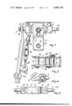
- FIG. 1 is a plan view of the device according to a first embodiment of the invention
- FIG. 2 is a side elevational view of a detail of the embodiment in FIG. 1, and in particular of the guide member rigidly affixed to the pulling machine;
- FIG. 3 is a front view of a detail of the embodiment in FIG. 1, and particularly of the supporting member for supporting the ends of said arms;
- FIG. 4 is a partially sectional side view of the embodiment of FIG. 1;
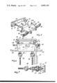
- FIG. 5 is a general perspective view of a second embodiment of the invention, subdivided into the basic components thereof;
- FIG. 6 is a plan view of the embodiment of FIG. 5;
- FIG. 7 is a partially sectional side view of the embodiment of FIG. 5;
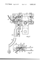
- FIG. 8 is a plan view of a third embodiment of the invention featuring additional locking means having a temporary or permanent action.
- FIG. 9 is a fragmentary side view of the embodiment of FIG. 8.
- the first embodiment of the device comprises first a plate member 1, which is rigidly connected to the pulling machine by means of bolts, not shown in the drawings.
- the plate member 1 may be a part of the frame of the pulling machine.
- Two metal plates, an upper and lower one, respectively 2 and 3, are welded to the plate member 1 such as to form together a guide 4 for a substantially bar-like element 5.
- the guide 4 and the bar-like element will be called hereinafter also draw bar member 4 and cross-bar member 5, respectively.
- the two metal plates, respectively 2 and 3 are each provided with three pairs of matching bores, respectively 2a and 3a, 2b and 3b, 2c and 3c.
- the bar-like element 5 is first provided with a through slotted hole 6 receiving a clevis pin 7 inserted through the matching bores 2a and 3a.
- said element 5 is provided with two substantially cylindrical projections or stop means 10, which abut on the plate member 1.
- the points on the plate member 1 where the stop means 10 abut against the plate member 1, will be called hereinafter also "abutment means".
- the ends of said bar element 5 are provided with connecting pins 11, through ball joints 12, for the lever arms 13. Pins 11a, inserted through the bores 11b, prevent said ball joints 12 from withdrawing apart.
- the divergence of the lever arms 13 may be adjusted by means of screw members 14 which are connected by an eye 14a to the hook 9 on one side, and on the opposite side, by means of an eye 14b to another eye 13a which is welded to the lever arm 13.
- 15a there is identified in the drawings, in a very schematic manner since it is well known in the art, a connection for the tilt-up device, usually a hydraulically operated device, not shown in the drawings.
- a pin 15 which is effective to prevent the bar element 5 from sliding backwards.
- a towing pin 16 is also insertable, if desired.
- FIGS. 5, 6, and 7 show a second embodiment of the invention.
- a plate 18, whereto a pin 19 is welded is also connected to a plate 20 (rigidly affixed to the pulling machine) through two projections 21, which are welded to the plate 20 and provided with bores wherethrough the pin 19 is inserted.
- the plate 18 is free to rotate with the pin 19 in the bores of projections 21; a through slotted hole 22 being formed in the plate 18.
- a hollow member 23 accomodates the plate 18 therewithin.
- the member 23 is provided with two matching holes or bores 24 wherethrough a pin 25 is inserted which is free to slide into the slot 22.
- two pins 26 are connected to the member 23, whereabout lever arms 27 are allowed to swing which are provided with ball joints 28.
- the divergence angle of the arms 27 is made adjustable by acting on an adjustment means which is identical to the means used in said first embodiment and identified in FIGS. 6 and 7 with the numeral 29.
- the arms 27, as is clearly seen, pass inside the guide yokes 30.
- this second embodiment of the invention may be described briefly as follows.
- the position of the member 23 with respect to the other structural components is the one shown in FIG. 6.
- the member 23 is allowed, therefore, to execute angular movements about the pin 25.
- the lever arms 27 are lifted up, by means of a hydraulic system not shown, the plate 18 and member 23 rotate about the pin 19.
- the weight of the member 23 causes the latter to descend down to a point where the cylindrical surfaces 23a abut the projections 21, thus preventing the member 23 from rotating about the pin 25.
- the device comprises a solid box member 31, whereto two plate-like members 32 are attached perpendicularly thereto, which are rigidly connected to the pulling machine by means of pins inserted through the bores 33 or 34, according to the design of the three-point hitch being used.
- a solid box member 31 whereto two plate-like members 32 are attached perpendicularly thereto, which are rigidly connected to the pulling machine by means of pins inserted through the bores 33 or 34, according to the design of the three-point hitch being used.
- two plates 35 and 36 are welded which are similar to 2 and 3 in FIG. 1, said plates acting as a guide for a swing bar member 37, substantially similar to 5 in FIG. 1.
- This swing bar 37 is provided with a different locking and adjustment system for its movement, which comprises a through screw 38 with locknut 39.
- Screw 38 has a hole 40 in the head thereof which in locking position is adapted to receive a locking pin 41 when the respective head of the screw 38 is inserted between two vertical spaced members 43 attached to the member 31.
- Pin 41 is retained by means of a staple spring 41a.
- Member pairs 43 have respective holes for the pin 41 provided with a handle for hand operation.
- a circular notch has been formed such as to provide a flat face 44 acting as a seat for a temporary locking member 45.
- Said member 45 comprises an arm 46 attached through a hinge connection 47 to the member 31.
- a roller 48 is provided which contacts the flat face 44.
- a compression spring 49 connected between the pin 50 of the roller and member 31, holds the member 46 in the position 51 shown in dotted lines.
- a metal cable 52 passing over the pin 48 is attached to the pin of the symmetrical member 46, not shown. Said cable 52 is then led through a sleeve 53 up to a control member, not shown.
- lever arms 54 constitute swingable abutment means for the cross-bar 37 and the cable 52 a control means for swinging the swingable abutment means from an operative into a non operative position.
- the embodiment just described operates as follows. If it is desired to permanently lock the machine in its rest position, following operation of the hydraulic lift system, the swing bar member 37 is forwardly shifted so that hole 40 is positioned in register with the member 43 and the pins 41 are inserted in their seats. The whole assembly is thus rigidly locked and any undesired oscillations are effectively prevented.
- the cable control 52 is activated, thereby the members 45 are brought to engage in the flat seats at the ends of the member 37. Any horizontal rotation of the implement with respect to the machine is thus prevented.
- the hitch structure according to the invention fully achieves the objects intended. It provides, in fact, for a swivelling movement of any implement with respect to the tractive machine.
- This swivelling action makes the invention specially suitable, and even necessary, for articulated machines or track-type machines which, in the absence of swivel hitch systems for their implements or attachments, would remain otherwise unable to manoeuver while at work with their implements installed.
- This is specially advantageous in that it permits optimum performance on an agricultural job, while providing at the same time a far more efficient use of the energy available.
- the device according to the invention is, moreover, structurally simple and easy and economical to manufacture.
- the materials used, as well as the dimensions may be any ones to suit differing requirements.
Landscapes
- Life Sciences & Earth Sciences (AREA)
- Zoology (AREA)
- Engineering & Computer Science (AREA)
- Mechanical Engineering (AREA)
- Soil Sciences (AREA)
- Environmental Sciences (AREA)
- Agricultural Machines (AREA)
Applications Claiming Priority (2)
| Application Number | Priority Date | Filing Date | Title |
|---|---|---|---|
| IT41667/74A IT1024014B (it) | 1974-09-02 | 1974-09-02 | Struttura di dispositivo per asso ciare snodabilmente attrezzi per la voro particolarmente per l agricoltura quali aratri e simili a macchine trainanti quali trattori |
| IT41667/74 | 1974-09-02 |
Publications (1)
| Publication Number | Publication Date |
|---|---|
| US4045143A true US4045143A (en) | 1977-08-30 |
Family
ID=11252770
Family Applications (1)
| Application Number | Title | Priority Date | Filing Date |
|---|---|---|---|
| US05/609,126 Expired - Lifetime US4045143A (en) | 1974-09-02 | 1975-08-29 | Swivel hitch structure |
Country Status (5)
| Country | Link |
|---|---|
| US (1) | US4045143A (it) |
| DE (1) | DE2538616A1 (it) |
| FR (1) | FR2282779A1 (it) |
| GB (1) | GB1522314A (it) |
| IT (1) | IT1024014B (it) |
Cited By (5)
| Publication number | Priority date | Publication date | Assignee | Title |
|---|---|---|---|---|
| US4268056A (en) * | 1978-08-29 | 1981-05-19 | Kubota, Ltd. | Structure for attaching hitch to tractor |
| US20060219809A1 (en) * | 2005-04-01 | 2006-10-05 | Thompson Dennis G | Spray boom suspension lock assembly |
| CN103935204A (zh) * | 2014-03-28 | 2014-07-23 | 浙江龙虎锻造有限公司 | 一种悬挂摆臂 |
| EP4147548A1 (fr) * | 2021-09-10 | 2023-03-15 | Kuhn-Huard S.A.S | Machine agricole avec une tête d'attelage munie d'un dispositif de verrouillage |
| US11685204B2 (en) | 2021-01-14 | 2023-06-27 | Swivel King, LLC | Hitch for an agricultural vehicle |
Families Citing this family (2)
| Publication number | Priority date | Publication date | Assignee | Title |
|---|---|---|---|---|
| FR2617365A1 (fr) * | 1987-06-30 | 1989-01-06 | Etienne Joseph | Dispositif d'articulation pivotante pour l'attelage des charrues portees |
| FR2651637B1 (fr) * | 1989-09-14 | 1992-01-24 | Naud Expl Charrues | Perfectionnement aux tetes d'attelage pour charrues. |
Citations (12)
| Publication number | Priority date | Publication date | Assignee | Title |
|---|---|---|---|---|
| USRE21989E (en) | 1941-12-30 | Tractor dttlkmknt | ||
| US2344474A (en) * | 1941-02-08 | 1944-03-14 | Allis Chalmers Mfg Co | Two-way plow |
| US2430732A (en) * | 1944-09-11 | 1947-11-11 | Int Harvester Co | Implement mount for tractors |
| US2611304A (en) * | 1950-11-18 | 1952-09-23 | Int Harvester Co | Tractor-mounted implement |
| US2793880A (en) * | 1954-07-26 | 1957-05-28 | Deere & Co | Hitch device of the connection facilitating type |
| US2935147A (en) * | 1955-08-01 | 1960-05-03 | Deere & Co | Hitch device |
| US3056458A (en) * | 1959-06-03 | 1962-10-02 | Harold P Gray | Tractor hitch organization |
| US3107736A (en) * | 1962-03-05 | 1963-10-22 | Mellen William Fisk | Means operated in response to movement of an implement to a raised position for locking the implement against lateral sway |
| GB1053977A (it) * | 1964-02-21 | 1967-01-04 | ||
| US3321030A (en) * | 1965-10-20 | 1967-05-23 | Int Harvester Co | Self-adjusting implement hitch for tractors |
| US3731750A (en) * | 1971-02-16 | 1973-05-08 | Heath Int Inc | Plow hitch |
| US3865404A (en) * | 1974-05-17 | 1975-02-11 | Dale R Schwartz | Mounting unit for a tractor pulled mower |
Family Cites Families (3)
| Publication number | Priority date | Publication date | Assignee | Title |
|---|---|---|---|---|
| US2697973A (en) * | 1952-02-04 | 1954-12-28 | Deere & Co | Hitch connection for plows |
| FR1274943A (fr) * | 1960-08-03 | 1961-11-03 | Koho Es Gepipari Miniszterium | Machine de travail du sol traînée à réglage automatique suivant la forme du sol |
| FR1396516A (fr) * | 1964-03-12 | 1965-04-23 | Huard Ucf | Dispositif d'attelage articulé pour machines agricoles |
-
1974
- 1974-09-02 IT IT41667/74A patent/IT1024014B/it active
-
1975
- 1975-08-29 US US05/609,126 patent/US4045143A/en not_active Expired - Lifetime
- 1975-08-29 GB GB35739/75A patent/GB1522314A/en not_active Expired
- 1975-08-29 DE DE19752538616 patent/DE2538616A1/de active Pending
- 1975-08-29 FR FR7526606A patent/FR2282779A1/fr not_active Withdrawn
Patent Citations (12)
| Publication number | Priority date | Publication date | Assignee | Title |
|---|---|---|---|---|
| USRE21989E (en) | 1941-12-30 | Tractor dttlkmknt | ||
| US2344474A (en) * | 1941-02-08 | 1944-03-14 | Allis Chalmers Mfg Co | Two-way plow |
| US2430732A (en) * | 1944-09-11 | 1947-11-11 | Int Harvester Co | Implement mount for tractors |
| US2611304A (en) * | 1950-11-18 | 1952-09-23 | Int Harvester Co | Tractor-mounted implement |
| US2793880A (en) * | 1954-07-26 | 1957-05-28 | Deere & Co | Hitch device of the connection facilitating type |
| US2935147A (en) * | 1955-08-01 | 1960-05-03 | Deere & Co | Hitch device |
| US3056458A (en) * | 1959-06-03 | 1962-10-02 | Harold P Gray | Tractor hitch organization |
| US3107736A (en) * | 1962-03-05 | 1963-10-22 | Mellen William Fisk | Means operated in response to movement of an implement to a raised position for locking the implement against lateral sway |
| GB1053977A (it) * | 1964-02-21 | 1967-01-04 | ||
| US3321030A (en) * | 1965-10-20 | 1967-05-23 | Int Harvester Co | Self-adjusting implement hitch for tractors |
| US3731750A (en) * | 1971-02-16 | 1973-05-08 | Heath Int Inc | Plow hitch |
| US3865404A (en) * | 1974-05-17 | 1975-02-11 | Dale R Schwartz | Mounting unit for a tractor pulled mower |
Cited By (7)
| Publication number | Priority date | Publication date | Assignee | Title |
|---|---|---|---|---|
| US4268056A (en) * | 1978-08-29 | 1981-05-19 | Kubota, Ltd. | Structure for attaching hitch to tractor |
| US20060219809A1 (en) * | 2005-04-01 | 2006-10-05 | Thompson Dennis G | Spray boom suspension lock assembly |
| US7429003B2 (en) | 2005-04-01 | 2008-09-30 | Cnh Canada, Ltd. | Spray boom suspension lock assembly |
| CN103935204A (zh) * | 2014-03-28 | 2014-07-23 | 浙江龙虎锻造有限公司 | 一种悬挂摆臂 |
| US11685204B2 (en) | 2021-01-14 | 2023-06-27 | Swivel King, LLC | Hitch for an agricultural vehicle |
| EP4147548A1 (fr) * | 2021-09-10 | 2023-03-15 | Kuhn-Huard S.A.S | Machine agricole avec une tête d'attelage munie d'un dispositif de verrouillage |
| FR3126842A1 (fr) * | 2021-09-10 | 2023-03-17 | Kuhn-Huard S.A.S. | Machine agricole avec une tête d’attelage munie d’un dispositif de verrouillage bloquant de sa traverse |
Also Published As
| Publication number | Publication date |
|---|---|
| IT1024014B (it) | 1978-06-20 |
| DE2538616A1 (de) | 1976-03-11 |
| FR2282779A1 (fr) | 1976-03-26 |
| GB1522314A (en) | 1978-08-23 |
Similar Documents
| Publication | Publication Date | Title |
|---|---|---|
| US3654999A (en) | Implement carrier | |
| US3529674A (en) | Foldable multiple section earthworking implement | |
| US3648780A (en) | Control mechanism for disk harrow | |
| US4561505A (en) | Hinge mechanism for folding tool bar assembly including hook engageable over pivotal connection | |
| US3539016A (en) | Actuating means for foldable implement carriage | |
| CA1306448C (en) | Auto-fold sprayer | |
| US4251181A (en) | Implement coupling apparatus for boom-type vehicle | |
| US4119156A (en) | Implement frame with caster wheel and lock therefor | |
| US4606413A (en) | Hydraulic leveler arrangement | |
| US4045143A (en) | Swivel hitch structure | |
| US3292949A (en) | Locking mechanisms for hitches | |
| US2564355A (en) | Grader blade locking and manipulating means | |
| US4260321A (en) | Lock mechanism for securing a backhoe boom and swing frame for transport | |
| US2685159A (en) | Offset disk harrow | |
| US3173497A (en) | Harrow attachment | |
| US5154239A (en) | Reversible plow with spring-biased trip shanks | |
| US5129463A (en) | Conservation tillage implement convertible for end transport | |
| US2913059A (en) | Plow beam trip for two-way plow | |
| US2734438A (en) | Hitch link | |
| US2996126A (en) | Implement connection for tractors | |
| US3008732A (en) | Hitch assembly | |
| US2788227A (en) | Combination hitch and tongue support actuator | |
| US2824505A (en) | Agricultural implement and support vehicle therefor | |
| US3379457A (en) | Hitch with weight-transferring drawbar coupling | |
| US3274712A (en) | Retractable scarifier |