US4021232A - Cast iron melting process - Google Patents
Cast iron melting process Download PDFInfo
- Publication number
- US4021232A US4021232A US05/600,117 US60011775A US4021232A US 4021232 A US4021232 A US 4021232A US 60011775 A US60011775 A US 60011775A US 4021232 A US4021232 A US 4021232A
- Authority
- US
- United States
- Prior art keywords
- iron
- recarburizer
- melt
- melting process
- cast iron
- Prior art date
- Legal status (The legal status is an assumption and is not a legal conclusion. Google has not performed a legal analysis and makes no representation as to the accuracy of the status listed.)
- Expired - Lifetime
Links
- 229910001018 Cast iron Inorganic materials 0.000 title claims abstract description 54
- 238000010309 melting process Methods 0.000 title claims abstract description 47
- XEEYBQQBJWHFJM-UHFFFAOYSA-N Iron Chemical compound [Fe] XEEYBQQBJWHFJM-UHFFFAOYSA-N 0.000 claims abstract description 493
- 229910052742 iron Inorganic materials 0.000 claims abstract description 246
- 230000001590 oxidative effect Effects 0.000 claims abstract description 97
- 238000006243 chemical reaction Methods 0.000 claims abstract description 93
- 239000002893 slag Substances 0.000 claims abstract description 44
- QVGXLLKOCUKJST-UHFFFAOYSA-N atomic oxygen Chemical compound [O] QVGXLLKOCUKJST-UHFFFAOYSA-N 0.000 claims abstract description 38
- 239000001301 oxygen Substances 0.000 claims abstract description 38
- 229910052760 oxygen Inorganic materials 0.000 claims abstract description 38
- 229910052799 carbon Inorganic materials 0.000 claims abstract description 33
- 238000007664 blowing Methods 0.000 claims abstract description 18
- 238000007600 charging Methods 0.000 claims abstract description 18
- 239000003795 chemical substances by application Substances 0.000 claims abstract description 18
- 238000010891 electric arc Methods 0.000 claims abstract 3
- 239000011572 manganese Substances 0.000 claims description 79
- 229910001141 Ductile iron Inorganic materials 0.000 claims description 47
- 238000002844 melting Methods 0.000 claims description 46
- 230000008018 melting Effects 0.000 claims description 46
- 239000011159 matrix material Substances 0.000 claims description 44
- 229910000859 α-Fe Inorganic materials 0.000 claims description 41
- 229910052748 manganese Inorganic materials 0.000 claims description 33
- OKTJSMMVPCPJKN-UHFFFAOYSA-N Carbon Chemical compound [C] OKTJSMMVPCPJKN-UHFFFAOYSA-N 0.000 claims description 31
- 229910000831 Steel Inorganic materials 0.000 claims description 31
- 239000010959 steel Substances 0.000 claims description 31
- PWHULOQIROXLJO-UHFFFAOYSA-N Manganese Chemical compound [Mn] PWHULOQIROXLJO-UHFFFAOYSA-N 0.000 claims description 13
- MYMOFIZGZYHOMD-UHFFFAOYSA-N Dioxygen Chemical compound O=O MYMOFIZGZYHOMD-UHFFFAOYSA-N 0.000 claims description 8
- 229910001882 dioxygen Inorganic materials 0.000 claims description 8
- 230000003647 oxidation Effects 0.000 claims description 8
- 238000007254 oxidation reaction Methods 0.000 claims description 8
- 238000010438 heat treatment Methods 0.000 claims description 7
- 239000000463 material Substances 0.000 claims description 7
- 239000006253 pitch coke Substances 0.000 claims description 6
- 239000012159 carrier gas Substances 0.000 claims description 4
- 229910002804 graphite Inorganic materials 0.000 claims description 3
- 239000010439 graphite Substances 0.000 claims description 3
- 239000007789 gas Substances 0.000 claims 1
- 239000002245 particle Substances 0.000 claims 1
- 229910052710 silicon Inorganic materials 0.000 abstract description 31
- 235000000396 iron Nutrition 0.000 abstract 1
- 239000000203 mixture Substances 0.000 description 36
- 229910052804 chromium Inorganic materials 0.000 description 17
- 239000010703 silicon Substances 0.000 description 14
- 238000000034 method Methods 0.000 description 12
- 230000008569 process Effects 0.000 description 12
- 239000000155 melt Substances 0.000 description 10
- 229910000805 Pig iron Inorganic materials 0.000 description 9
- 239000000126 substance Substances 0.000 description 8
- 229910052802 copper Inorganic materials 0.000 description 6
- 238000004519 manufacturing process Methods 0.000 description 5
- 229910052718 tin Inorganic materials 0.000 description 4
- 230000008901 benefit Effects 0.000 description 3
- 230000007246 mechanism Effects 0.000 description 3
- 229910001562 pearlite Inorganic materials 0.000 description 3
- 230000003449 preventive effect Effects 0.000 description 3
- 230000009471 action Effects 0.000 description 2
- 239000000571 coke Substances 0.000 description 2
- 238000002156 mixing Methods 0.000 description 2
- 238000000137 annealing Methods 0.000 description 1
- 238000010314 arc-melting process Methods 0.000 description 1
- 238000005266 casting Methods 0.000 description 1
- 238000002485 combustion reaction Methods 0.000 description 1
- 239000003302 ferromagnetic material Substances 0.000 description 1
- 239000008187 granular material Substances 0.000 description 1
- 238000005087 graphitization Methods 0.000 description 1
- 230000005484 gravity Effects 0.000 description 1
- 239000012535 impurity Substances 0.000 description 1
- 230000006698 induction Effects 0.000 description 1
- 239000004615 ingredient Substances 0.000 description 1
- 150000002505 iron Chemical class 0.000 description 1
- 239000007791 liquid phase Substances 0.000 description 1
- 229910052751 metal Inorganic materials 0.000 description 1
- 239000002184 metal Substances 0.000 description 1
- 239000007800 oxidant agent Substances 0.000 description 1
- 239000012071 phase Substances 0.000 description 1
- 239000012256 powdered iron Substances 0.000 description 1
- 239000002994 raw material Substances 0.000 description 1
- 239000007787 solid Substances 0.000 description 1
- 239000007858 starting material Substances 0.000 description 1
- 238000009628 steelmaking Methods 0.000 description 1
Images


Classifications
-
- C—CHEMISTRY; METALLURGY
- C21—METALLURGY OF IRON
- C21C—PROCESSING OF PIG-IRON, e.g. REFINING, MANUFACTURE OF WROUGHT-IRON OR STEEL; TREATMENT IN MOLTEN STATE OF FERROUS ALLOYS
- C21C1/00—Refining of pig-iron; Cast iron
- C21C1/10—Making spheroidal graphite cast-iron
-
- C—CHEMISTRY; METALLURGY
- C21—METALLURGY OF IRON
- C21C—PROCESSING OF PIG-IRON, e.g. REFINING, MANUFACTURE OF WROUGHT-IRON OR STEEL; TREATMENT IN MOLTEN STATE OF FERROUS ALLOYS
- C21C1/00—Refining of pig-iron; Cast iron
-
- Y—GENERAL TAGGING OF NEW TECHNOLOGICAL DEVELOPMENTS; GENERAL TAGGING OF CROSS-SECTIONAL TECHNOLOGIES SPANNING OVER SEVERAL SECTIONS OF THE IPC; TECHNICAL SUBJECTS COVERED BY FORMER USPC CROSS-REFERENCE ART COLLECTIONS [XRACs] AND DIGESTS
- Y02—TECHNOLOGIES OR APPLICATIONS FOR MITIGATION OR ADAPTATION AGAINST CLIMATE CHANGE
- Y02P—CLIMATE CHANGE MITIGATION TECHNOLOGIES IN THE PRODUCTION OR PROCESSING OF GOODS
- Y02P10/00—Technologies related to metal processing
- Y02P10/20—Recycling
Definitions
- This invention relates to a cast iron melting process, and more particularly to a cast iron melting process which is well adapted to obtain an original or primary melt for spheroidal graphite cast iron; a majority of whose matrix consists of a ferritic structure in as cast state.
- the spheroidal graphite cast iron may be classified into that having a ferrite matrix and that having a pearlite matrix. Among those, the spheroidal graphite cast iron having a ferrite matrix has good ductility and machinability, so that it finds a wide use as a raw material for parts of motor vehicles and other mechanical parts. Hitherto, the spheroidal graphite cast iron has been produced by applying a heat treatment to the spheroidal graphite cast iron having mainly a pearlite matrix.
- the spheroidal graphite cast iron having a ferrite matrix in as cast state may dispense with heat treatment, thus presenting advantages in improving its production efficiency as well as saving energy.
- Manganese is contained in commercially available steel scaps in amounts of 0.4 to 0.7%, in general, so that the desired production of spheroidal graphite cast iron having a ferrite matrix in as cast state should be achieved by adding a great amount of special pig iron containing least of elements, such as Mn, which hinders the graphitizing.
- an oxidizing agent for instance iron ore, mill scale, etc.
- a slag forming agent in an attempt to reduce the contents of C and Si by using the oxidizing power of the slag formed by aforementioned agents on the surface of an iron melt, or oxygen is blown into an iron melt.
- Mn content is necessarily reduced. Accordingly, this may be possibly applied to the process for producing a primary melt of a low manganese content for the production of the spheroidal graphite cast iron having a ferrite matrix in as cast state.
- Table 2 shows the loss in the amounts of respective elements, due to oxidation, in which the aforesaid loss depends on the contents of the respective elements and temperatures.
- silicon is selectively oxidized in the case of a high-Si melt, while carbon is selectively oxidized at an elevated temperature, thus failing to achieve the object to remove manganese.
- the recarburizing treatment is effected by injecting graphite powder into a steel bath in a furnace, or by transferring iron melt into a ladle, after which the recarburizing treatment is applied.
- the temperature of the steel bath should be risen extremely high, and as a result it will accompany heat loss. This further causes a lowered recarburizing yield, so that it is difficult to add a great amount of carbon.
- the melt is transferred into a ladle for recarburizing treatment, there results a further greater heat loss and lowering in ecomony and productivity, requiring a great amount of man hours.
- a cast iron melting process comprising the steps of: charging recarburizer in the lower portion of an arc furnace; charging and/or blowing a material adapted to form a slag, coupled with iron scraps, for carrying out the melting operation, whereby a recarburizing reaction of said recarburizer with an iron melt is carried out in parallel with an oxidizing reaction of the aforesaid iron melt with oxidative slag in the low temperature range i.e., during the melting of the iron scraps and/or immediately after the melting of the iron scraps.
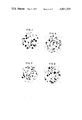
- FIG. 1 is microscopic structures of spheroidal graphite cast iron having a ferrite matrix in as cast state;
- FIG. 2 is a plot showing the variation in oxygen affinity, of the principal elements contained in iron
- FIG. 3 is a longitudinal cross-sectional view illustrating a recarburizing mechanism in an arc furnace
- FIGS. 4 and 5 are explanatory views of recarburizing and oxidizing reactions within the arc furnace.
- FIGS. 6 to 12 are photographs illustrating the microscopic structures of spheroidal graphite cast iron having a ferrite matrix in as cast state, which have been obtained in the examples according to the present invention.
- FIG. 2 shows the variation in the oxygen affinity at varying temperatures, of the principal elements.
- the affinities of Si, Mn and Cr are greater than that of C in the low temperature range, so that those elements are selectively oxidized.
- the temperature is raised to a high temperature (a high temperature range of above 1440° C.), then carbon is selectively oxidized.
- the present invention is thus based on the aforesaid metallurgical reaction. (The first aspect of the invention.)
- the recarburizing phenomenon in an arc furnace has been clarified according to the present invention. More specifically, as shown in FIG. 3, when a recarburizer 1 of a given amount and a granular form is placed in the bottom portion of an arc furnace 8, and iron scraps are charged into the upper portion of the furnace for melting, then iron scraps which have been melted due to an arc flow downwards in the form of melt droplets, so that the iron melt 2 covers the surface of recarburizer 1 to define an interface 4.
- the size of the recarburizer 1 is selected to a suitable value, then the iron melt 2 will not make ingress into voids among the grains of recarburizer 1 due to the surface tension prevailing thereon.
- the recarburizer 1 does not float to the surface of a melt, until the completion of the melting operation, despite the low specific gravity thereof, thus remaining in the bottom of the furnace, so that the recarburizing reaction proceeds through its contacting surface with the iron melt 2, and the recarburizer is consumed accordingly.
- the present invention is secondarily based on the aforesaid recarburizing mechanism. (The second aspect of the invention.)
- the first point may be achieved by utilizing the first aspect of the present invention, which refers to the metallurgical reaction, while the second point may be achieved by utilizing the aforesaid second aspect of the present invention which refers to the recarburizing mechanism.
- powdered recarburizer such as pitch cokes of a size of no more than 10 mm is placed in the bottom portion of an arc furnace in a manner that the top surface of the recarburizer will be flat substantially in the horizontal direction, and then a strong oxidative slag-forming agent is scattered thereon, followed by superposition of given iron scraps thereon.
- the iron scraps which have been melted due to the heat at a high temperature, of an arc will flowdown in the form of a droplet, thereby melting the slag-forming agent having a low melting point, while melt droplets themselves undergo a strong oxidizing action, so that the elements having a strong oxygen affinity are removed according to the oxidizing reaction, while the oxidized products thereof are fused together with the slag-forming agent to thereby form slags.
- the melt droplets further flow down and reach the surface of the recarburizer in the bottom portion of the furnace. With the progress of such operations, there appears a condition in the furnace, wherein as shown in FIG. 4 the two phases of iron melt 2 and slags 3 cover the surface of the recarburizer 1.
- While pich cokes of a size of no more than 6 mm are used as recarburizer in one example of the aforesaid operation, it is preferable to use cokes of a size of no more than 6 mm, considering a recarburizing yield and the like. In addition, for improving the recarburizing reaction and the recarburizing yield, it is preferable to use the size of no less than 2.5 mm. In either case, however, it is not to mention that granules of a size of no more than the aforesaid size may be present therein.
- the recarburizer 1 contacts only the iron melt 2, being separated from slags 2 by the medium of iron melt 2.
- the carburizer 1 is gradually melted into the iron melt 2 through the interface 4 between the recarburizer 1 and the iron melt 2, so that the carbon content in the iron melt 2 is increased accordingly.
- the iron melt 2 contacts with the slags 3 on its top surface, so that the removal of elements such as Si, Mn, Cr and the like according to the oxidizing reaction proceeds along the interface 5.
- the temperature of the iron melt 2 is maintained as low as 1440° C., since the iron melt is present in the course of melting of iron scraps 6 or immediately after the melting thereof, thus failing to oxidize carbon, which is an effective element and which has been introduced through the interface 4 into the iron melt, as has been described in conjunction with the first aspect of the present invention.
- Shown at 7 is melt droplets, and at 8 an arc furnace.
- the oxidizing reaction and recarburizing reaction take place in a manner separated by the medium of the iron melt 2, while the aforesaid reactions proceed along the upper and lower interfaces 4, 5 at the same time, so that there may be obtained a primary melt adapted for the spheroidal graphite cast iron of a high C, low Mn, and low Cr content, which iron has a ferrite matrix in as cast state.
- recarburizer is placed on the bottom of a furnace, and then iron scraps are charged in a given amount, followed by melting. Then, the iron scraps which have been melted due to the heat at a high temperature, of an arc flow down in the form of droplets to cover the surfaces of recarburizer.
- oxygen is blown, with the surface of the recarburizer covered with the iron melt, i.e., with the blown oxygen kept from direct contact with the recarburizer, then the recarburizing reaction will proceed along the interface between the recarburizer and the iron melt, while the oxidizing reaction will take place at the same time, due to oxygen being blown.
- the recarburizer is melted into the iron melt gradually, so that carbon content in the iron melt is increased accordingly.
- elements such as Si, Mn, Cr and the like in the iron melt are rapidly removed according to the oxidation due to oxygen being blown.
- the temperature of the iron melt is maintained low less than 1440° C., since iron scraps are in the course of melting, so that carbon is not oxidized, which is an effective element and which has been melted through the interface into the iron melt, as has been described in the first aspect of the present invention.
- powdered recarburizer such as pitch cokes of a size of no more than 10 mm is charged in the bottom portion of an arc furnace in a manner that its surface becomes flat substantially in the horizontal direction, and then sponge iron is mixed with the total charge of scraps in amount of 2 to 10% by weight in terms of unreduced iron equivalent amount, after which iron scraps of a given amount are charged thereon.
- the iron scraps which have been melted due to the heat at a high temperature, of an arc flow down in the form of droplets to melt unreduced part in the sponge iron, while the droplets are subjected to a strong oxidizing action, so that elements having strong oxygen affinity, such as Si, Mn, Cr and the like, are removed according to the oxidizing reaction, the oxidized products forming molten slag.
- the droplets further flow down and reach the surface of the recarburizer in the bottom portion of the furnace. According to the aforesaid process, the two liquid phases of iron melt 2 and slag 3 cover the recarburizer 1 as shown in FIG. 5.
- pitch cokes of a size of no more than 10 mm are used.
- the pitch cokes of a size of no more than 6 mm considering a recarburizing yield.
- the size should preferably be no more than 2.5 mm. In either case, it is needless to mention that the pitch cokes of a size of below the aforesaid range may be contained therein.
- the recarburizer 1 is in contact with only the iron melt 2, while the recarburizer 1 is separated by the medium of the iron melt 2. Accordingly, the recarburizer 1 is gradually dissolved into the iron melt through the interface 4 between the recarburizer 1 and the iron melt 2, and carbon content in the iron melt 2 is gradually increased accordingly.
- the iron melt 2 is in contact with the slag 3 on its top surface, so that the rapid removal of elements such as Si, Mn, Cr according to the oxidizing reaction proceeds along the interface 5.
- the temperature of the iron melt 2 is maintained as low as below 1440° C., since the sponge iron and iron scraps 19 are in the course of melting or immediately after the melting, so that, as has been described with reference to the first aspect of the present invention, the effective element, carbon, will not be oxidized, which has been dissolved through the interface 4 into the iron melt 2.
- melt droplets In passing, shown at 7 are melt droplets, and at 8 an arc furnace.
- both the oxidizing reaction and the recarburizing reaction proceed in parallel along the interfaces 4, 5, without interference therebetween due to the intervening iron melt 2, so that a primary melt for spheroidal graphite cast iron having a ferrite matrix in as cast state may be achieved, the aforesaid cast iron having a high carbon content, low Mn content and low Cr content.
- the utilization of the unreduced components in the sponge iron as an oxidative slag-forming agent not only enhances the oxidizing reaction but also permits to utilize the reducing iron having low content impurities as an iron source, so that there may be achieved spheroidal graphite cast iron having a ferrite matrix in as cast state, which is better than those obtained in the so called iron ore process and oxygen process.
- the sponge iron is a ferromagnetic material, so that a lifting magnet may be used for charging and hence the melting operation may be simplified.
- the aforesaid example refers to the case of resorting to the strong oxidative slag which has been obtained from the unreduced iron contained in the sponge iron.
- description will be turned to an example wherein, as defined in claim 5, the amount of the sponge iron is reduced and part of the strong oxidative slag is supplemented due to the oxygen blowing, so that the oxidizing reaction according to the strong oxidative slag and the recarburizing reaction according to the recarburizer are carried out in parallel with each other.
- the recarburizer is placed on the bottom of a furnace and then an iron scraps of a given amount and sponge iron of no more than 2% in terms of the equivalent amount of unreduced iron, to the total amount of iron scraps charged are charged.
- the temperature of the iron melt is maintained at no more than 1440° C., since the iron melt is yet in the course of melting of iron scraps, so that carbon as an effective element will not be oxidized, which has been dissolved into the iron melt through the medium of an interface, as has been described with reference to the first aspect of the present invention.
- the oxidizing reaction and recarburizing reaction proceed in parallel with each other, so that a primary melt for spheroidal graphite cast iron having a ferrite matrix in as cast state may be achieved, the aforesaid cast iron having a high carbon low Mn and low Cr content.
- the recarburizer is placed in the bottom portion of an arc furnace, and then iron scraps of a given amount are charged therein.
- iron scraps which have been melted due to the heat at a high temperature, of an arc flow down in the form of droplets to cover the surface of the recarburizer.
- the iron ore thus being blown oxidizes the iron melt along an interface between the iron melt and the iron ore and removes Si, Mn, Cr and the like according to the oxidizing reaction, while oxygen used as a carrier gas reacts with iron in a solid state (unmelted) and iron melt, so that Si, Mn, Cr and the like are removed according to the oxidizing reaction.
- the temperature of the iron melt is maintained no more than 1440° C., since the iron melt is in the course of melting of iron scraps, so that carbon as an effective component will not be oxidized.
- the oxidizing reaction in this respect proceeds much rapidly, as compared with the cases of using only iron ore and only oxygen.
- the grain size of the iron ore in this case should preferably be in the range of from 0.5 to 5 mm. However, the grain size of no more than 15 mm achieves the intended purposes.
- the slag in the furnace was removed and the melt was heated to a temperature of 1500° C., after which the iron melt was transferred to a low frequency induction furnace, where carbon and silicon were added thereto, thereby obtaining a primary melt for spheroidal graphite cast iron.
- the following is the chemical composition of the spheroidal graphite cast iron having a ferrite matrix in as cast state, which was obtained by subjecting the primary melt to sphroidizing treatment and inoculating treatment.
- the microscopic structures of the above cast iron are shown in FIG. 6.
- the temperature of the iron melt was found to be 1350° C. at the time of melting down, while the recarburizing reaction and oxidizing reaction were carried out in parallel with each other, thus obtaining an iron melt of the following composition:
- silicon should be added to the above iron melt to be used as a primary melt for the sphroidal graphite cast iron having a ferrite matrix in as cast state, then silicon was added thereto to thereby obtain an iron melt adapted as a primary melt for the spheroidal graphite cast iron having a ferrite matrix in as cast state, and having a composition as follows:
- FIG. 7 shows the microscopic structures thereof.
- silicon should be added to the above iron melt to be used as a primary melt for the spheroidal graphite cast iron having a ferrite matrix in as cast state, silicon was added thereto to thereby obtain an iron melt but adapted as a primary melt for the spheroidal graphite cast iron having a ferrite matrix in as cast state and having a composition as follows:
- FIG. 8 shows the microscopic structures thereof.
- an oxidizing reaction takes place in the course of melting or immediately after the melting of the iron scraps, i.e., in a relatively low temperature range, so that the loss of carbon, which is effective element, may be minimized, while insuring a value of no less than 90% for a recarburizing yield, and yet the graphitizing preventive elements such as Mn, Cr and the like may be removed according to oxidation, thus achieving the objects of the present invention.
- FIG. 9 shows the microscopic structures thereof.
- the following example refers to the case where the amount of sponge iron was reduced, and the oxidizing reaction was supplemented by blowing oxygen into the furnace.
- compositions of steel scraps and sponge iron as used in the present example are as follows:
- silicon should be added to the above iron melt to be used as a primary melt for the spheroidal graphite cast iron having a ferrite matrix in as cast state, the silicon was added thereto to thereby obtain an iron melt best adapted as a primary melt for the spheroidal graphite cast iron having a ferrite matrix in as cast state and having the following composition:
- FIG. 10 shows the microscopic structures thereof.
- an oxidizing reaction takes place in the course of melting or immediately after the melting of the iron scraps, i.e., in a relatively low temperature range, so that the loss of carbon, which is effective element, may be minimized, while insuring a value of no less than 90 % for a recarburizing yield, and yet the graphitizing preventive elements such as Mn, Cr and the like may be removed according to the oxidation, so that there may be obtained cast iron of the type described, which is less in contents of Cu, Sn.
- FIG. 11 shows the microscopic structures thereof.
- the following example refers to the case where the grain size of iron ore is considerably large.
- silicon should be added to the above melt to be used as a primary melt for the spheroidal graphite cast iron having a ferrite matrix in as cast state, silicon was added thereto, and the iron melt having the following composition was obtained:
- FIG. 12 shows the microscopic structures thereof.
- the oxidizing reaction rapidly takes place in the course of melting or immediately after the melting of iron scraps, i.e., in a relatively low temperature range, so that the loss of carbon, which is effective element, may be minimized, while insuring a value of no less than 90 % for a recarburizing yield, and yet the graphitizing preventive elements such as Mn, Cr and the like may be removed according to oxidiation, thus achieving the objects of the present invention.
- the manganese content be no more than 0.25 %, for producing spheroidal graphite cast iron which dispenses with annealing, and has a ferrite matrix in as cast state.
- Mn content of steel scraps as a principal source of the iron for casting is as high as 0.4 to 0.7% and the contents of Cu and Sn are high in some cases. Accordingly, there has not been disclosed an attempt to provide an industrial process to obtain a primary melt for spheroidal graphite cast iron having a ferrite matrix in as cast state and a low Mn content, principally from commercially available steel scraps, so that a great amount of special type pig iron having a low Mn content should be charged.
- the recarburizing reaction is carried out simultaneously or in parallel with the oxidizing reaction due to the use of oxidative slag which has been produced by a strong oxidative slag-forming agent or oxygen which is being blown into the furnace; or the recarburizing reaction may be carried out in parallel with the oxidizing reaction due to the use of unreduced iron contained in the sponge iron and or oxygen which has been blown into the furnace, as required; or otherwise the recarburizing reaction may be carried out in parallel with the oxidizing reaction according to the blowing of iron ore, which is carried by oxygen; so that the oxidizing reaction may be accelerated.
- the melting process of the invention there result less loss of C, Si which are effective elements, and an improved recarburizing yeild, so that there is not required a great amount of operation hours for recarburizing operation, presenting economical and industrial advantage, as compared with the prior art melting processes, in which the recarburizing reaction is carried out separately of the oxidizing reaction, i.e., in which removal of Mn is carried out after the recarburizing operation, or recarburizing operation is carried out after the removal of Mn.
- the melting process according to the present invention presents considerable advantages in industries.
Landscapes
- Chemical & Material Sciences (AREA)
- Engineering & Computer Science (AREA)
- Materials Engineering (AREA)
- Metallurgy (AREA)
- Organic Chemistry (AREA)
- Refinement Of Pig-Iron, Manufacture Of Cast Iron, And Steel Manufacture Other Than In Revolving Furnaces (AREA)
- Vertical, Hearth, Or Arc Furnaces (AREA)
- Manufacture And Refinement Of Metals (AREA)
Applications Claiming Priority (6)
| Application Number | Priority Date | Filing Date | Title |
|---|---|---|---|
| JA49-90797 | 1974-08-09 | ||
| JP9079774A JPS5118911A (ja) | 1974-08-09 | 1974-08-09 | Chutetsuyokaiho |
| JP5139775A JPS51126914A (en) | 1975-04-30 | 1975-04-30 | Process for melting cast iron |
| JA50-51397 | 1975-04-30 | ||
| JP5139675A JPS51126913A (en) | 1975-04-30 | 1975-04-30 | Process for melting cast iron |
| JA50-51396 | 1975-04-30 |
Publications (1)
| Publication Number | Publication Date |
|---|---|
| US4021232A true US4021232A (en) | 1977-05-03 |
Family
ID=27294302
Family Applications (1)
| Application Number | Title | Priority Date | Filing Date |
|---|---|---|---|
| US05/600,117 Expired - Lifetime US4021232A (en) | 1974-08-09 | 1975-07-29 | Cast iron melting process |
Country Status (4)
| Country | Link |
|---|---|
| US (1) | US4021232A (enExample) |
| DE (2) | DE2435339A1 (enExample) |
| FR (1) | FR2281429A1 (enExample) |
| GB (1) | GB1524362A (enExample) |
Cited By (2)
| Publication number | Priority date | Publication date | Assignee | Title |
|---|---|---|---|---|
| US6149709A (en) * | 1997-09-01 | 2000-11-21 | Kabushiki Kaisha Kobe Seiko Sho | Method of making iron and steel |
| US20170342515A1 (en) * | 2014-12-12 | 2017-11-30 | Kinoshita Manufactory Co.,Ltd. | Methods for manganese removal of cast iron |
Citations (1)
| Publication number | Priority date | Publication date | Assignee | Title |
|---|---|---|---|---|
| US3524742A (en) * | 1967-07-05 | 1970-08-18 | Jackson L Williams | Process for refining steel |
-
1975
- 1975-07-29 US US05/600,117 patent/US4021232A/en not_active Expired - Lifetime
- 1975-08-05 GB GB3273075A patent/GB1524362A/en not_active Expired
- 1975-08-07 DE DE19752435339 patent/DE2435339A1/de active Pending
- 1975-08-07 FR FR7524731A patent/FR2281429A1/fr active Granted
- 1975-08-07 DE DE2535339A patent/DE2535339C3/de not_active Expired
Patent Citations (1)
| Publication number | Priority date | Publication date | Assignee | Title |
|---|---|---|---|---|
| US3524742A (en) * | 1967-07-05 | 1970-08-18 | Jackson L Williams | Process for refining steel |
Cited By (2)
| Publication number | Priority date | Publication date | Assignee | Title |
|---|---|---|---|---|
| US6149709A (en) * | 1997-09-01 | 2000-11-21 | Kabushiki Kaisha Kobe Seiko Sho | Method of making iron and steel |
| US20170342515A1 (en) * | 2014-12-12 | 2017-11-30 | Kinoshita Manufactory Co.,Ltd. | Methods for manganese removal of cast iron |
Also Published As
| Publication number | Publication date |
|---|---|
| DE2535339C3 (de) | 1978-05-24 |
| DE2535339B2 (de) | 1977-10-06 |
| DE2535339A1 (de) | 1976-04-01 |
| FR2281429A1 (fr) | 1976-03-05 |
| DE2435339A1 (de) | 1976-02-19 |
| GB1524362A (en) | 1978-09-13 |
| FR2281429B1 (enExample) | 1978-11-17 |
Similar Documents
| Publication | Publication Date | Title |
|---|---|---|
| CA3022024C (en) | Method and apparatus for the production of cast iron, cast iron produced according to said method | |
| JPH10195513A (ja) | 金属鉄の製法 | |
| JP2009079303A (ja) | ステンレス鋼製造工程廃棄物を再利用したステンレス鋼の製造方法 | |
| US4537629A (en) | Method for obtaining high purity ductile iron | |
| US5725631A (en) | Composite charge for metallurgical processing | |
| US20030106395A1 (en) | Agglomerates containing iron and at least one further element of groups 5 or 6 of the periodic system | |
| US4021232A (en) | Cast iron melting process | |
| GB1566028A (en) | Process for continuously smelting high quality steel | |
| JPH07188831A (ja) | ステンレス鋼の製造方法および装置 | |
| US6478840B1 (en) | Reduction of chromium content in slag during melting of stainless steel in electric arc furnaces | |
| US3240591A (en) | Manufacture of ferromanganese alloy | |
| RU2102496C1 (ru) | Способ выплавки стали в основной мартеновской печи | |
| US4235623A (en) | Continuous smelting method for ferrochrome | |
| RU2186856C1 (ru) | Композиционная шихта для выплавки легированных сталей | |
| RU2153023C1 (ru) | Способ переработки минерального сырья, содержащего марганец, с извлечением металлов | |
| JP2003049216A (ja) | 溶鋼製造方法 | |
| JP4295557B2 (ja) | ステンレス鋼製造工程廃棄物を再利用したステンレス鋼の製造方法 | |
| US3329497A (en) | Process for the manufacture of ferromanganese-silicon | |
| JP4210603B2 (ja) | 鋳鉄溶湯中のマンガン除去方法及び球状黒鉛鋳鉄の製造方法 | |
| RU2049119C1 (ru) | Способ производства высококачественной стали в дуговой печи | |
| SU572504A1 (ru) | Способ получени железа и его сплавов из железорудных материалов | |
| US1969886A (en) | Method of manufacturing ferro alloys | |
| KR900700387A (ko) | Sic, MnC 및 합금철의 생성방법 | |
| CA1195509A (en) | Method of producing metallic nickel | |
| SU1687627A1 (ru) | Способ выплавки хромистой стали с содержанием хрома до 5% |