US4005516A - Hand tool having double toggle linkage - Google Patents
Hand tool having double toggle linkage Download PDFInfo
- Publication number
- US4005516A US4005516A US05/666,553 US66655376A US4005516A US 4005516 A US4005516 A US 4005516A US 66655376 A US66655376 A US 66655376A US 4005516 A US4005516 A US 4005516A
- Authority
- US
- United States
- Prior art keywords
- jaw
- toggle
- ram
- extending
- jaws
- Prior art date
- Legal status (The legal status is an assumption and is not a legal conclusion. Google has not performed a legal analysis and makes no representation as to the accuracy of the status listed.)
- Expired - Lifetime
Links
Images


Classifications
-
- H—ELECTRICITY
- H01—ELECTRIC ELEMENTS
- H01R—ELECTRICALLY-CONDUCTIVE CONNECTIONS; STRUCTURAL ASSOCIATIONS OF A PLURALITY OF MUTUALLY-INSULATED ELECTRICAL CONNECTING ELEMENTS; COUPLING DEVICES; CURRENT COLLECTORS
- H01R43/00—Apparatus or processes specially adapted for manufacturing, assembling, maintaining, or repairing of line connectors or current collectors or for joining electric conductors
- H01R43/01—Apparatus or processes specially adapted for manufacturing, assembling, maintaining, or repairing of line connectors or current collectors or for joining electric conductors for connecting unstripped conductors to contact members having insulation cutting edges
- H01R43/015—Handtools
-
- Y—GENERAL TAGGING OF NEW TECHNOLOGICAL DEVELOPMENTS; GENERAL TAGGING OF CROSS-SECTIONAL TECHNOLOGIES SPANNING OVER SEVERAL SECTIONS OF THE IPC; TECHNICAL SUBJECTS COVERED BY FORMER USPC CROSS-REFERENCE ART COLLECTIONS [XRACs] AND DIGESTS
- Y10—TECHNICAL SUBJECTS COVERED BY FORMER USPC
- Y10T—TECHNICAL SUBJECTS COVERED BY FORMER US CLASSIFICATION
- Y10T29/00—Metal working
- Y10T29/53—Means to assemble or disassemble
- Y10T29/5313—Means to assemble electrical device
- Y10T29/532—Conductor
- Y10T29/53209—Terminal or connector
- Y10T29/53213—Assembled to wire-type conductor
- Y10T29/53217—Means to simultaneously assemble multiple, independent conductors to terminal
-
- Y—GENERAL TAGGING OF NEW TECHNOLOGICAL DEVELOPMENTS; GENERAL TAGGING OF CROSS-SECTIONAL TECHNOLOGIES SPANNING OVER SEVERAL SECTIONS OF THE IPC; TECHNICAL SUBJECTS COVERED BY FORMER USPC CROSS-REFERENCE ART COLLECTIONS [XRACs] AND DIGESTS
- Y10—TECHNICAL SUBJECTS COVERED BY FORMER USPC
- Y10T—TECHNICAL SUBJECTS COVERED BY FORMER US CLASSIFICATION
- Y10T29/00—Metal working
- Y10T29/53—Means to assemble or disassemble
- Y10T29/5313—Means to assemble electrical device
- Y10T29/532—Conductor
- Y10T29/53209—Terminal or connector
- Y10T29/53213—Assembled to wire-type conductor
- Y10T29/53222—Means comprising hand-manipulatable implement
- Y10T29/53226—Fastening by deformation
Definitions
- This invention relates to plier-type hand tools having a double toggle actuating linkage.
- the disclosed embodiment is particularly directed to the achievement of a tool for installing a multi-contact electrical connector on a flat conductor cable although other uses for the invention will be apparent from the following description.
- Tools having toggle mechanisms are shown, for example, in U.S. Pat. Nos. 2,327,368; 2,436,497; 2,464,472 and 1,362,595.
- U.S. Pat. No. 3,820,055 discloses and claims a multi-contact electrical connector which is installed on a flat conductor cable by simply locating the cable adjacent to a cable-receiving surface of the connector housing and moving the cable normally of its plane towards that surface.
- Contact terminals extend from the cable-receiving surface and these terminals penetrate the cable and establish electrical contact with the conductors upon such movement of the cable.
- Connectors of the type shown in U.S. Pat. No. 3,820,055 are now being manufactured with 50 and more contact terminals extending from the cable-receiving surface for engagement with the 50 conductors of the cable.
- this number of conductors and terminals is involved, a relatively high force is required to install the connector on the cable and the installation process must be carried out with a high degree of precision and control if a satisfactory installation is to result.
- most hand tools are designed such that they are incapable of accommodating a relatively wide (3 inches or more) cable between their jaws.
- most types of hand tools if modified for connector-cable installation processes, would tend to undergo elastic deflection when the connector is installed on the cable because of the high stresses developed and the deflection, in turn, would result in non-uniform application of forces on the cable and connector which would, in turn, lead to unsatisfactory installation.
- a plier-type hand tool having parallel jaws and a reciprocable ram in one of the jaws which is movable towards the outer jaw.
- the ram is reciprocated by a removable handle which, upon movement thereof, straightens two toggle mechanisms to drive the ram along its working stroke.
- the arrangement of the toggle mechanisms is such that a high thrust or force is developed in the ram, a thrust which is more than adequate to install a relatively high count flat cable on a connector.
- the toggle arrangement is also such that a deep throat is provided in the tool and a relatively wide flat cable can be accommodated between the jaws of the tool.
- a removable tension member extends between the ends of the jaws so that excessive deflection of the tool (as a result of high localized stresses) is avoided.
- a further object is to provide a hand tool capable of being used on a relatively large workpiece such as a relatively wide multi-conductor cable.
- a further object is to provide a hand tool which is not subject to excessive elastic deflection when put to use.
- a further object is to provide plier-type hand tool which is convenient to use by a person of average strength and which is capable of developing a high force or thrust.
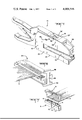
- FIG. 1 is a perspective view of a preferred form of tool in accordance with the invention.
- FIG. 2 is a side view, partly in section, of a preferred embodiment of the invention, this view showing the positions of the parts when the ram is in its raised or retracted position.
- FIG. 3 is a view similar to FIG. 1 but showing the positions of the parts when the ram is in its bottom dead center position.
- FIGS. 4 and 5 are views taken along the lines 3--3 and 4--4 of FIG. 3.
- FIG. 6 is a perspective view of a fixture having an integral tension member which forms part of the invention.
- FIG. 7 is an exploded view of a multi-contact electrical connector and a flat conductor cable to which the connector is attached.
- the herein disclosed embodiment of the invention is intended to install a connector 6 (FIG. 7) on a flat conductor cable 2 of the type having a plurality of parallel side-by-side conductors.
- the connector 6 may be of the general type disclosed and claimed in U.S. Pat. No. 3,820,055 and has a generally prismatic housing 8 which has a cable receiving face 10 and a face 12 on the opposite side thereof from the cable receiving face.
- a plurality of contact terminals 4 extend normally from the face 10 and these terminals are connected to the individual conductors in the cable by merely moving the cable relatively towards the face 10 so that the terminals penetrate the cable and establish electrical contact with the conductors in the cable.
- a cover member 11 is provided which is latched to the housing and which covers the ends of the terminals after the connector has been installed on the cable.
- Connectors of this type may have a relatively large number of terminals when they are intended for cables having the large numbers of conductors therein.
- the connector is of a relatively small size (e.g. having five or ten terminals), as shown in U.S. Pat. No. 3,820,055, it is a simple matter to install the connector on the cable but the installation of a connector having say 50 terminals on a cable having the same number of conductors requires a relatively high force and conventional and relatively simple tools are not suitable for the operation.
- a tool 14 in accordance with the invention comprises a frame having a yoke portion 16 and a pair of parallel fixed jaws 18, 20 extending from the yoke portion.
- the opposed surfaces of the jaws are spaced apart to provide a gap 22 and this gap extends inwardly for a substantial distance to the yoke 16 so that a relatively wide cable can be accommodated between the jaws.
- the tool frame may be comprised of spaced-apart stamped plates 23, 23' (FIG. 4) and suitable spacer means as shown at 24, may be provided between the plates and secured to the plates by fasteners as shown.
- the tool frame can be of cast and machined parts if desired.
- the upper jaw 18 has a solid block 26 on its free end and the lower arm 20 has an enlarged end for reasons discussed below.
- a fixed handle 28 extends from the yoke 16 in substantial alignment with the jaw 20.
- a movable handle 30 is normally spaced from the fixed handle and pivoted to the tool as also described below.
- a reciprocable ram 32 is slidably contained in the first jaw 18, this ram being generally U-shaped as shown in FIG. 4 and having a web portion 34 and sidewalls 36, 36'.
- the sidewalls are slidably received in guideways 40 provided in the inner surfaces of each of the plates 23, 23' and the outwardly facing surfaces of a bearing block 38 which is secured between the plates 23, 23' by fasteners 39.
- the base portion 34 and the sidewalls 36, 36' of the rams can be separate parts, if desired, since they are held together by a pivot pin 46 which is described below.
- the ram 32 has an elongated pressure bar 42 secured thereto which extends in the direction of the jaws 18, 20.
- This pressure bar is advantageously dimensioned to apply a uniform force to the surface of a suitable fixture which is used to press the cable and the connector against each other.
- a specific form of fixture for installing the connector on the cable is shown in my co-pending application Ser. No. 666,552, although other types of fixtures can be used if desired.
- the ram 32 is reciprocated by first and second toggle mechanisms, the first toggle mechanism comprising a pair of parallel links 44, 44' which are pivotally connected at their lower ends, as viewed in FIG. 4, to the portion 34 of the ram by a pin 46.
- the upper ends of the links 44, 44' are pivotally connected by pin 50 to a single link 48 which is, in turn, pivotally connected by a pin 52 to the bearing block 38.
- a pair of parallel straightening links 54 are pivotally connected to the pin 50 on each side of the upper toggle link 48 and these straightening links extend leftwardly, as viewed in FIG. 2, to the second toggle mechanism.
- This second toggle mechanism comprises a link 58 which is connected at one end to the pin 56 and to a knee joint pivot pin 60 at its other end.
- Parallel links 62 are also connected to pin 60 and have their other ends pivoted to a fixed pivot 64 on an ear 66 which is integral with the spacer block 24.
- the movable handle 30 is pivoted to the bearing block 38 by a pivot pin 68 which is disposed adjacent to the first toggle mechanisms so that the movable handle extends leftwardly in FIG. 2 beside and past, the straightening links 64 and past the second toggle mechanism.
- Movable handle 30 is internally recessed as shown at 70 and has an inclined surface 72 which receives the knee joint of the second toggle mechanism when the handle is closed from the position of FIG. 2 to the position of FIG. 3.
- the ends of the knee joint pin 60 extend into slightly elongated slots 75 in the handle so that the second toggle will be straightened when handle 30 is swung towards handle 28.
- Guidance slots 74 are provided in the side plates 23, 23' and receive the ends of the pivot pin 56 of the second toggle mechanism so that when the handle is closed, this second toggle mechanism is forced to straighten itself and drive the connecting link 54 rightwardly. It should also be noted that a notch 76 is provided in the handle 30 to provide clearance for the ends of the pivot pin 56 as will be apparent from FIG. 2 and 3.
- the first toggle comprising the link means 44, 44' and the link 48 is normally maintained in a broken condition by a spring 78 which is secured at one end to the straightening link 54 and which is secured at its other end to a pin 79. This spring biases the link 54 leftwardly thereby maintaining both toggle mechanisms in a broken condition.
- a full stroke compelling mechanism is provided, as is common practice on tools for crimping or otherwise compressing electrical connecting devices.
- This full stroke compelling mechanism may comprise a rod 84 which has its end pivoted to the fixed handle 28 and which extends into a housing 82 which is pivoted to the handle 30.
- Ratchet teeth (not shown) are provided on the rod 84 and are engaged by a pawl in the housing 82, the arrangement being such that if the operator starts to close the handles, he must continue to do so until complete closure is achieved.
- fixture 84 when the connector is being installed on the cable, the fixture having means for holding the connector and cable in their proper positions relative to each other for installation.
- a preferred form of fixture is described in detail in application Ser. No. 666,552 and the fixture need not be described here.
- a tension member 86 extends between the free ends of jaws 18, 20 and this tension member is integral with a base plate portion 87 of the fixture. As shown in FIG. 5, the tension member has laterally extended portions 88, 90 on its ends so that it can be slid into complementary recesses in the block 26 and in the end of jaw 20. This tension member prevents excessive flexure of the jaws when the tool is used so that the dimensional precision of the tool is maintained during use.
- the connector housing and the cable are positioned in the fixture 84 and the fixture is then slid into the tool and between the jaws until it is in the position of FIG. 2. Thereafter, the movable handle is squeezed towards the fixed end and the toggles are straightened to drive the ram downwardly and move the cable relatively against the cable receiving face of the connector.
- U-shaped ram 32 which is driven downwardly upon straightening of the first toggle mechanism.
- the sidewalls 36, 36' of this ram provide an extensive bearing surface as is required for smooth operation without the development of unduly high stresses and for bearing loads.
- the first toggle mechanism is contained in the ram (note that when the ram is in its raised position, bearing block 30 is between the sidewalls 36, 36') and bulkiness or excessive size in this portion of the tool is avoided.
Landscapes
- Engineering & Computer Science (AREA)
- Manufacturing & Machinery (AREA)
- Manufacturing Of Electrical Connectors (AREA)
- Gripping Jigs, Holding Jigs, And Positioning Jigs (AREA)
- Hand Tools For Fitting Together And Separating, Or Other Hand Tools (AREA)
Priority Applications (11)
| Application Number | Priority Date | Filing Date | Title |
|---|---|---|---|
| US05/666,553 US4005516A (en) | 1976-03-15 | 1976-03-15 | Hand tool having double toggle linkage |
| GB6615/77A GB1569355A (en) | 1976-03-15 | 1977-02-17 | Compression handtools |
| CA272,161A CA1078588A (en) | 1976-03-15 | 1977-02-21 | Compression handtools |
| IT20764/77A IT1086213B (it) | 1976-03-15 | 1977-02-28 | Perfezionamenti apportati a utensili a mano di compressione |
| NL7702277A NL7702277A (nl) | 1976-03-15 | 1977-03-03 | Drukhandgereedschap. |
| BE175650A BE852288A (fr) | 1976-03-15 | 1977-03-09 | Pince a main notamment pour le montage d'un connecteur sur un cable plat |
| FR7707118A FR2344376A1 (fr) | 1976-03-15 | 1977-03-10 | Pince a main notamment pour le montage d'un connecteur sur un cable plat |
| DE2711063A DE2711063C2 (de) | 1976-03-15 | 1977-03-14 | Handpreßwerkzeug |
| ES456806A ES456806A1 (es) | 1976-03-15 | 1977-03-14 | Perfeccionamientos introducidos en una herramienta de mano de compresion. |
| SE7702945A SE427809B (sv) | 1976-03-15 | 1977-03-15 | Klemverktyg |
| JP2857477A JPS52112788A (en) | 1976-03-15 | 1977-03-15 | Manual compression tool |
Applications Claiming Priority (1)
| Application Number | Priority Date | Filing Date | Title |
|---|---|---|---|
| US05/666,553 US4005516A (en) | 1976-03-15 | 1976-03-15 | Hand tool having double toggle linkage |
Publications (1)
| Publication Number | Publication Date |
|---|---|
| US4005516A true US4005516A (en) | 1977-02-01 |
Family
ID=24674528
Family Applications (1)
| Application Number | Title | Priority Date | Filing Date |
|---|---|---|---|
| US05/666,553 Expired - Lifetime US4005516A (en) | 1976-03-15 | 1976-03-15 | Hand tool having double toggle linkage |
Country Status (11)
| Country | Link |
|---|---|
| US (1) | US4005516A (member.php) |
| JP (1) | JPS52112788A (member.php) |
| BE (1) | BE852288A (member.php) |
| CA (1) | CA1078588A (member.php) |
| DE (1) | DE2711063C2 (member.php) |
| ES (1) | ES456806A1 (member.php) |
| FR (1) | FR2344376A1 (member.php) |
| GB (1) | GB1569355A (member.php) |
| IT (1) | IT1086213B (member.php) |
| NL (1) | NL7702277A (member.php) |
| SE (1) | SE427809B (member.php) |
Cited By (23)
| Publication number | Priority date | Publication date | Assignee | Title |
|---|---|---|---|---|
| US4040179A (en) * | 1976-01-13 | 1977-08-09 | Amp Incorporated | Apparatus for mating first and second portions of an electrical connector |
| US4070754A (en) * | 1976-10-22 | 1978-01-31 | Thomas & Betts Corporation | Hand tool for joining objects |
| EP0004283A1 (en) * | 1978-03-17 | 1979-10-03 | Gardner-Denver Company | Tool for applying connectors to flexible cable |
| US4308657A (en) * | 1979-09-10 | 1982-01-05 | Gte Products Corporation | Connector terminating apparatus |
| USRE30848E (en) * | 1976-10-22 | 1982-01-19 | Thomas & Betts Corporation | Hand tool for joining objects |
| US4386461A (en) * | 1981-10-29 | 1983-06-07 | Arco Pipe Line Company | Ribbon cable connector tool |
| US4527328A (en) * | 1982-12-27 | 1985-07-09 | Panduit Corp. | Portable mass termination tool |
| DE4101284A1 (de) * | 1991-01-17 | 1992-07-23 | Weidmueller C A Gmbh Co | Mit einem kniehebelmechanismus versehenes geraet zum bearbeiten von arbeitsgegenstaenden durch druck |
| US5267464A (en) * | 1991-12-30 | 1993-12-07 | Cleland John G | Pipe ring crimping tool |
| DE19644807A1 (de) * | 1996-10-28 | 1998-05-07 | Connectool Gmbh & Co | Werkzeug mit einem Mehrfach-Kniehebelmechanismus |
| US20060179647A1 (en) * | 2005-02-15 | 2006-08-17 | John Mezzalingua Associates, Inc. | Tool adaptor |
| US20060213248A1 (en) * | 2005-03-25 | 2006-09-28 | Mil3, Inc. | Two-stroke tool |
| US20060277746A1 (en) * | 2004-05-14 | 2006-12-14 | Fluke Corporation | Multiple-wire termination tool with translatable jack and cutting blade precision alignment carrier |
| US20080163664A1 (en) * | 2007-01-08 | 2008-07-10 | Wezag Gmbh Werkzeugfabrik | Pliers for Pressing Work Pieces |
| US20090064754A1 (en) * | 2007-09-10 | 2009-03-12 | John Mezzalingua Associates, Inc. | Hydraulic compression tool for installing a coaxial cable connector and method of operating thereof |
| US20110173810A1 (en) * | 2007-09-10 | 2011-07-21 | John Mezzalingua Associates, Inc. | Pneumatic compression tool and method of usingthe compression tool to attach a cable connector |
| US8516696B2 (en) | 2007-09-10 | 2013-08-27 | John Mezzalingua Associates, LLC | Hydraulic compression tool for installing a coaxial cable connector and method of operating thereof |
| US8595928B2 (en) | 2007-09-10 | 2013-12-03 | John Mezzalingua Associates, LLC | Method for installing a coaxial cable connector onto a cable |
| US8661656B2 (en) | 2007-09-10 | 2014-03-04 | John Mezzallingua Associates, LLC | Hydraulic compression tool for installing a coaxial cable connector and method of operating thereof |
| US9089958B2 (en) | 2011-07-01 | 2015-07-28 | Mil3 Inc. | Multi-functional tool for flexible pipe and related methods |
| US20150270689A1 (en) * | 2012-12-18 | 2015-09-24 | Smart Wires Inc. | Installation fixture for installing devices on power lines |
| CN109590946A (zh) * | 2019-01-18 | 2019-04-09 | 中车洛阳机车有限公司 | 一种屏蔽线屏蔽框专用钳 |
| US10819077B2 (en) | 2007-09-10 | 2020-10-27 | John Mezzalingua Associates, LLC | Compression tool with biasing member |
Citations (2)
| Publication number | Priority date | Publication date | Assignee | Title |
|---|---|---|---|---|
| US3492854A (en) * | 1968-02-21 | 1970-02-03 | Thomas & Betts Corp | High compression force staking tool |
| US3630068A (en) * | 1970-05-20 | 1971-12-28 | Edwin Floyd Jr | High compression for staking tool |
Family Cites Families (3)
| Publication number | Priority date | Publication date | Assignee | Title |
|---|---|---|---|---|
| US2018996A (en) * | 1934-03-24 | 1935-10-29 | Christians Frederick | Method and tool for clamping electrical couplings |
| DE1204600B (de) * | 1961-10-31 | 1965-11-04 | Amp Inc | Von Hand betaetigbares Andrueckwerkzeug |
| US3837211A (en) * | 1973-07-06 | 1974-09-24 | Amp Inc | Multi-stroke hand tool |
-
1976
- 1976-03-15 US US05/666,553 patent/US4005516A/en not_active Expired - Lifetime
-
1977
- 1977-02-17 GB GB6615/77A patent/GB1569355A/en not_active Expired
- 1977-02-21 CA CA272,161A patent/CA1078588A/en not_active Expired
- 1977-02-28 IT IT20764/77A patent/IT1086213B/it active
- 1977-03-03 NL NL7702277A patent/NL7702277A/xx active Search and Examination
- 1977-03-09 BE BE175650A patent/BE852288A/xx not_active IP Right Cessation
- 1977-03-10 FR FR7707118A patent/FR2344376A1/fr active Granted
- 1977-03-14 DE DE2711063A patent/DE2711063C2/de not_active Expired
- 1977-03-14 ES ES456806A patent/ES456806A1/es not_active Expired
- 1977-03-15 SE SE7702945A patent/SE427809B/xx not_active IP Right Cessation
- 1977-03-15 JP JP2857477A patent/JPS52112788A/ja active Pending
Patent Citations (2)
| Publication number | Priority date | Publication date | Assignee | Title |
|---|---|---|---|---|
| US3492854A (en) * | 1968-02-21 | 1970-02-03 | Thomas & Betts Corp | High compression force staking tool |
| US3630068A (en) * | 1970-05-20 | 1971-12-28 | Edwin Floyd Jr | High compression for staking tool |
Cited By (39)
| Publication number | Priority date | Publication date | Assignee | Title |
|---|---|---|---|---|
| US4040179A (en) * | 1976-01-13 | 1977-08-09 | Amp Incorporated | Apparatus for mating first and second portions of an electrical connector |
| FR2338592A1 (fr) * | 1976-01-13 | 1977-08-12 | Amp Inc | Appareil d'assemblage des deux parties d'un connecteur electrique |
| US4070754A (en) * | 1976-10-22 | 1978-01-31 | Thomas & Betts Corporation | Hand tool for joining objects |
| FR2368340A1 (fr) * | 1976-10-22 | 1978-05-19 | Thomas & Betts Corp | Outil manuel pour l'assemblage de deux ou de plusieurs objets |
| USRE30848E (en) * | 1976-10-22 | 1982-01-19 | Thomas & Betts Corporation | Hand tool for joining objects |
| EP0004283A1 (en) * | 1978-03-17 | 1979-10-03 | Gardner-Denver Company | Tool for applying connectors to flexible cable |
| US4174560A (en) * | 1978-03-17 | 1979-11-20 | Cooper Industries, Inc. | Tool for applying connectors to flexible cable |
| US4308657A (en) * | 1979-09-10 | 1982-01-05 | Gte Products Corporation | Connector terminating apparatus |
| US4386461A (en) * | 1981-10-29 | 1983-06-07 | Arco Pipe Line Company | Ribbon cable connector tool |
| US4527328A (en) * | 1982-12-27 | 1985-07-09 | Panduit Corp. | Portable mass termination tool |
| DE4101284A1 (de) * | 1991-01-17 | 1992-07-23 | Weidmueller C A Gmbh Co | Mit einem kniehebelmechanismus versehenes geraet zum bearbeiten von arbeitsgegenstaenden durch druck |
| US5267464A (en) * | 1991-12-30 | 1993-12-07 | Cleland John G | Pipe ring crimping tool |
| DE19644807A1 (de) * | 1996-10-28 | 1998-05-07 | Connectool Gmbh & Co | Werkzeug mit einem Mehrfach-Kniehebelmechanismus |
| US20060277746A1 (en) * | 2004-05-14 | 2006-12-14 | Fluke Corporation | Multiple-wire termination tool with translatable jack and cutting blade precision alignment carrier |
| US20060179647A1 (en) * | 2005-02-15 | 2006-08-17 | John Mezzalingua Associates, Inc. | Tool adaptor |
| US7607218B2 (en) * | 2005-02-15 | 2009-10-27 | John Mezzalingua Associates, Inc. | Tool adaptor |
| US20060213248A1 (en) * | 2005-03-25 | 2006-09-28 | Mil3, Inc. | Two-stroke tool |
| US7503201B2 (en) | 2005-03-25 | 2009-03-17 | Mil3, Inc. | Two-stroke tool |
| US7886570B2 (en) | 2005-03-25 | 2011-02-15 | Mil3, Inc. | Two-stroke tool |
| US20080163664A1 (en) * | 2007-01-08 | 2008-07-10 | Wezag Gmbh Werkzeugfabrik | Pliers for Pressing Work Pieces |
| DE102007001235A1 (de) * | 2007-01-08 | 2008-07-17 | Wezag Gmbh Werkzeugfabrik | Presszange zum Verpressen von Werkstücken |
| US8127589B2 (en) | 2007-01-08 | 2012-03-06 | Wezag Gmbh Werkzeugfabrik | Pliers for pressing work pieces |
| DE102007001235B4 (de) * | 2007-01-08 | 2010-06-02 | Wezag Gmbh Werkzeugfabrik | Presszange zum Verpressen von Werkstücken |
| US20090064754A1 (en) * | 2007-09-10 | 2009-03-12 | John Mezzalingua Associates, Inc. | Hydraulic compression tool for installing a coaxial cable connector and method of operating thereof |
| US8661656B2 (en) | 2007-09-10 | 2014-03-04 | John Mezzallingua Associates, LLC | Hydraulic compression tool for installing a coaxial cable connector and method of operating thereof |
| US20110179639A1 (en) * | 2007-09-10 | 2011-07-28 | John Mezzalingua Associates, Inc. | Pneumatic compression tool and method of using the compression tool to attach a cable connector |
| US7908741B2 (en) | 2007-09-10 | 2011-03-22 | John Mezzalingua Associates, Inc. | Hydraulic compression tool for installing a coaxial cable connector |
| US8272128B2 (en) | 2007-09-10 | 2012-09-25 | John Mezzalingua Associates, Inc. | Method of using a compression tool to attach a cable connection |
| US8516696B2 (en) | 2007-09-10 | 2013-08-27 | John Mezzalingua Associates, LLC | Hydraulic compression tool for installing a coaxial cable connector and method of operating thereof |
| US8595928B2 (en) | 2007-09-10 | 2013-12-03 | John Mezzalingua Associates, LLC | Method for installing a coaxial cable connector onto a cable |
| US20110173810A1 (en) * | 2007-09-10 | 2011-07-21 | John Mezzalingua Associates, Inc. | Pneumatic compression tool and method of usingthe compression tool to attach a cable connector |
| US11539179B2 (en) | 2007-09-10 | 2022-12-27 | John Mezzalingua Associates, LLC | Compression tool with biasing member |
| US10819077B2 (en) | 2007-09-10 | 2020-10-27 | John Mezzalingua Associates, LLC | Compression tool with biasing member |
| US9246294B2 (en) | 2007-09-10 | 2016-01-26 | John Mezzalingua Associates, LLC | Tool for attaching a cable connector to a cable |
| US9950413B2 (en) | 2011-07-01 | 2018-04-24 | Mil3 Inc. | Multi-functional tool for flexible pipe and related methods |
| US9089958B2 (en) | 2011-07-01 | 2015-07-28 | Mil3 Inc. | Multi-functional tool for flexible pipe and related methods |
| US9843176B2 (en) * | 2012-12-18 | 2017-12-12 | Smart Wires Inc. | Installation fixture for installing devices on power lines |
| US20150270689A1 (en) * | 2012-12-18 | 2015-09-24 | Smart Wires Inc. | Installation fixture for installing devices on power lines |
| CN109590946A (zh) * | 2019-01-18 | 2019-04-09 | 中车洛阳机车有限公司 | 一种屏蔽线屏蔽框专用钳 |
Also Published As
| Publication number | Publication date |
|---|---|
| FR2344376B1 (member.php) | 1980-07-11 |
| JPS52112788A (en) | 1977-09-21 |
| IT1086213B (it) | 1985-05-28 |
| ES456806A1 (es) | 1978-02-16 |
| FR2344376A1 (fr) | 1977-10-14 |
| SE7702945L (sv) | 1977-09-16 |
| CA1078588A (en) | 1980-06-03 |
| GB1569355A (en) | 1980-06-11 |
| DE2711063C2 (de) | 1987-04-09 |
| BE852288A (fr) | 1977-09-09 |
| DE2711063A1 (de) | 1977-09-29 |
| NL7702277A (nl) | 1977-09-19 |
| SE427809B (sv) | 1983-05-09 |
Similar Documents
| Publication | Publication Date | Title |
|---|---|---|
| US4005516A (en) | Hand tool having double toggle linkage | |
| US3903725A (en) | Tongs with a linear working stroke for pressing, perforating, separating and the like | |
| US4381661A (en) | Tool having two working jaws | |
| US4353240A (en) | Crimping tool | |
| US3837211A (en) | Multi-stroke hand tool | |
| US4396183A (en) | Power actuated clamp | |
| US6155095A (en) | Pliers including a pliers head and a positioning device | |
| US2992576A (en) | Hand crimping tool | |
| EP1820608B1 (en) | Link for crimping tool | |
| US4062218A (en) | Cutting or pressing appliances | |
| US5402561A (en) | Crimping tool having angularly offset crimping dies | |
| US5870925A (en) | Hand tool crimping a terminal onto a conductor | |
| US3174323A (en) | Crimping tool | |
| US2887916A (en) | Crimping tools | |
| GB1064356A (en) | Tool for crimping electrical connectors to wires | |
| GB1145859A (en) | Cable crimping tool, terminal and method of forming | |
| CA1086032A (en) | Apparatus for applying electrical connectors to cables | |
| US2774269A (en) | Crimping tool | |
| US2635494A (en) | Compressing tool with reversible jaws | |
| US4329891A (en) | Wire stripping tools | |
| US4934172A (en) | Compression tool for various sizes and shapes | |
| US20070199364A1 (en) | Crimping die and crimping tool | |
| US4337635A (en) | Compression tool | |
| GB1400908A (en) | Clamping tools | |
| US5680788A (en) | Power crimping tool having improved crimping mechanism for tape feed products |