US3998527A - Wide-angle photographic lens system with a short overall length - Google Patents
Wide-angle photographic lens system with a short overall length Download PDFInfo
- Publication number
- US3998527A US3998527A US05/577,016 US57701675A US3998527A US 3998527 A US3998527 A US 3998527A US 57701675 A US57701675 A US 57701675A US 3998527 A US3998527 A US 3998527A
- Authority
- US
- United States
- Prior art keywords
- sub
- lens
- respectively represent
- reference symbols
- sup
- Prior art date
- Legal status (The legal status is an assumption and is not a legal conclusion. Google has not performed a legal analysis and makes no representation as to the accuracy of the status listed.)
- Expired - Lifetime
Links
Images
Classifications
-
- G—PHYSICS
- G02—OPTICS
- G02B—OPTICAL ELEMENTS, SYSTEMS OR APPARATUS
- G02B13/00—Optical objectives specially designed for the purposes specified below
- G02B13/06—Panoramic objectives; So-called "sky lenses" including panoramic objectives having reflecting surfaces
-
- G—PHYSICS
- G02—OPTICS
- G02B—OPTICAL ELEMENTS, SYSTEMS OR APPARATUS
- G02B13/00—Optical objectives specially designed for the purposes specified below
- G02B13/18—Optical objectives specially designed for the purposes specified below with lenses having one or more non-spherical faces, e.g. for reducing geometrical aberration
Definitions
- the present invention relates to a wide-angle photographic lens system and, more particularly, to a wide-angle photographic lens system having a telephoto ratio (the value obtained by dividing the distance from the first lens surface of the lens system to the imaging plane by the focal length of the lens system as a whole) of about 0.9, short overall length and field angle of 62° or more.
- a telephoto ratio the value obtained by dividing the distance from the first lens surface of the lens system to the imaging plane by the focal length of the lens system as a whole
- a primary object of the present invention to provide a compact wide-angle photographic lens system having an aspherical surface of a shape which can be formed easily and of comparatively small area, especially offaxial aberration of said wide-angle photographic lens system being favorably corrected by means of said aspherical surface.
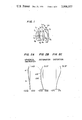
- the lens system according to the present invention is of a three-component four-element lens configuration in which a first lens component L 1 is a cemented doublet lens consisting of a positive lens and negative lens, a second lens component L 2 is a positive lens, and a third lens component L 3 is a negative meniscus lens, said lens system according to the present invention satisfying the following conditions when reference symbol f represents the focal length of the lens system as a whole, reference symbol f 1 represents the focal length of the first lens component L 1 , reference symbols n 1 and n 2 respectively represent refractive indices of respective lenses, i.e., the positive and negative lenses of the first lens component L 1 , reference symbols r 4 and r 5 respectively represent radii of curvature of the front and rear surfaces of the second lens component L 2 , and reference symbol f 3 represents the focal length of the third lens component L 3 .
- the surface r 6 on the object side of the third lens component L 3 is formed as an aspherical surface which is expressed by the following formulas (5) when x axis represents the direction of the optical axis and y axis represents the direction perpendicular to the optical axis. ##EQU2##
- the reason why the focal length f 1 of the first lens component L 1 is limited to the range of 1.2f ⁇ f 1 ⁇ 1.8f as defined by the condition (1) is to well balance the powers of the front lens group on the object side of the stop and of the rear lens group on the image side of the stop.
- the focal length f 1 of said front lens goup i.e., the first lens component L 1 is made shorter, it is possible to make the overall length of the lends system shorter.
- f 1 becomes shorter than 1.2f shown in the condition (1) it becomes difficult to correct aberrations favorably in case of the lens configuration according to the present invention.
- f 1 becomes larger than 1.8f the overall length of the lens system becomes long and, consequently, the object of the present invention to provide a compact lens system cannot be attained.
- the condition (2) is to define refractive indices of the first lens component L 1 .
- the difference of refractive indices of respective lenses of the first lens component L 1 which has power satisfying the above-mentioned condition (1), becomes smaller than 0.15, it is not desirable because symmetry of coma will be disturbed and, especially coma of lower rays becomes negative value.
- the condition (3) is to define radii of curvature r 4 and r 5 of surfaces on the object side and image side of the second lens component L 2 .
- This condition (3) is established for the purpose of correcting coma and distortion without changing the focal length of the lens system as a whole and overall length of the lens system when the first lens component L 1 constituting the front lens group is arranged to satisfy the above-mentioned conditions (1) and (2).
- - (r 4 /r 5 ) exceeds the upper limit of the condition (3), pincushion distortion becomes considerably large.
- - (r 4 /r 5 ) becomes smaller than the lower limit, distortion can be corrected favorably. In that case, however, coma of upper rays at the marginal portion becomes negative value and, moreover, the meridional image plane will largely incline toward the minus side.
- the focal length f 3 of the third lens component L 3 which is a negative meniscus lens is made short, it is advantageous for reducing the overall length of the lens system. If, however, f 3 becomes shorter than 0.4f defined by the condition (4), Petzval's sum becomes a negative value. Moreover, considerable pincushion distortion is caused and it becomes impossible to correct them by the first lens component L 1 and second lens component L 2 . If the focal length f 3 of the third lens component becomes longer than 0.8f, it becomes impossible to make the overall length of the lens system satisfactorily short by satisfying the conditions (1) through (3).
- the concave surface on the object side of the third lens component L 3 is formed as an aspherical surface which is expressed by formulas (5).
- FIG. 1 shows a sectional view of lens system according to Embodiments 1 through 5 of the present invention
- FIGS. 2A, 2B and 2C respectively show graphs illustrating aberration curves of the Embodiment 1;
- FIGS. 3A, 3B and 3C respectively show graphs illustrating aberration curves of the Embodiment 2;
- FIGS. 4A, 4B and 4C respectively show graphs illustrating aberration curves of the Embodiment 3;
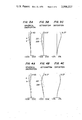
- FIGS. 5A, 5B and 5C respectively show graphs illustrating aberration curves of the Embodiment 4.
- FIGS. 6A, 6B and 6C respectively show graphs illustrating aberration curves of the Embodiment 5;
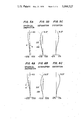
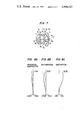
- FIG. 7 shows a sectional view of the lens system according to the Embodiment 6 of the present invention.
- FIGS. 8A, 8B and 8C respectively show graphs illustrating aberration curves of the Embodiment 6.
- an aspherical lens having an aspherical surface of small radius of curvature As above, a method to manufacture such lens by using plastic material may be considered besides the method to manufacture such aspherical lens directly from glass material. Besides, it is also known to manufacture an aspherical lens by providing a thin layer of plastic material on a surface of a spherical lens made of glass or plastic material so that the surface of said thin layer becomes an aspherical surface.
- the Embodiment 6 shows a lens system manufactured by such method. In this embodiment, a spherical lens is at first formed so that the thickness of the plastic layer to form the aspherical surface will become suitable for manufacture.
- the aspherical layer is provided on the spherical surface of said spherical lens. That is, in FIG. 7, reference symbol r' represents the radius of curvature of one surface of the spherical lens.
- the aspherical layer made of material having the refractive index n' and Abbe's number ⁇ ' is formed for the range of about 0.276 diameter so that the thickness of said aspherical layer from the spherical surface r' to aspherical surface r 6 on the optical axis becomes d'.
- reference symbols r 1 through r 7 respectively represent radii of curvature of respective lens surfaces
- reference symbols d 1 through d 6 respectively represent thicknesses of respective lenses and airspaces between respective lenses
- reference symbol n 1 through n 4 respectively represent refractive indices of respective lenses
- reference symbols ⁇ 1 through ⁇ 4 respectively represent Abee's numbers of respective lenses
- reference symbol S' represents the distance between the lens surface in the lens system closest to the image and the image plane
- referency symbol P represents the telephoto ratio
- reference symbols E, F, G and H respectively represent coefficients in formulas (5).
- the present invention provides a wide-angle photographic lens system having simple lens configuration and short overall length for which aberrations are corrected quite favorably.
Landscapes
- Physics & Mathematics (AREA)
- General Physics & Mathematics (AREA)
- Optics & Photonics (AREA)
- Lenses (AREA)
Abstract
A wide-angle photographic lens system with a short overall length comprising three lens components of four lenses, the surface on the object side of the third lens component being formed as an aspherical surface expressed by the following formulas: ##EQU1##
Description
1. Field of the Invention
The present invention relates to a wide-angle photographic lens system and, more particularly, to a wide-angle photographic lens system having a telephoto ratio (the value obtained by dividing the distance from the first lens surface of the lens system to the imaging plane by the focal length of the lens system as a whole) of about 0.9, short overall length and field angle of 62° or more.
2. Description of the Prior Art
As compact wide-angle photographic lens systems having short overall length like the above, those which have a plural number of aspherical surfaces in the lends system are known. Those lens systems having aspherical surfaces, however, have a disadvantage that it is difficult to produce lenses having aspherical surfaces.
It is, therefore, a primary object of the present invention to provide a compact wide-angle photographic lens system having an aspherical surface of a shape which can be formed easily and of comparatively small area, especially offaxial aberration of said wide-angle photographic lens system being favorably corrected by means of said aspherical surface.
As shown in FIG. 1, the lens system according to the present invention is of a three-component four-element lens configuration in which a first lens component L1 is a cemented doublet lens consisting of a positive lens and negative lens, a second lens component L2 is a positive lens, and a third lens component L3 is a negative meniscus lens, said lens system according to the present invention satisfying the following conditions when reference symbol f represents the focal length of the lens system as a whole, reference symbol f1 represents the focal length of the first lens component L1, reference symbols n1 and n2 respectively represent refractive indices of respective lenses, i.e., the positive and negative lenses of the first lens component L1, reference symbols r4 and r5 respectively represent radii of curvature of the front and rear surfaces of the second lens component L2, and reference symbol f3 represents the focal length of the third lens component L3.
1. 1.2f < f1 < 1.8f
2. n2 - n1 > o.15
3. 1.5 < - (r4 /r5) < 5
4. 0.4f < -f3 < 0.8f
In addition to the above-mentioned configuration, the surface r6 on the object side of the third lens component L3 is formed as an aspherical surface which is expressed by the following formulas (5) when x axis represents the direction of the optical axis and y axis represents the direction perpendicular to the optical axis. ##EQU2##
In the lens system of the above-mentioned configuration, the reason why the focal length f1 of the first lens component L1 is limited to the range of 1.2f < f1 < 1.8f as defined by the condition (1) is to well balance the powers of the front lens group on the object side of the stop and of the rear lens group on the image side of the stop. When the focal length f1 of said front lens goup, i.e., the first lens component L1 is made shorter, it is possible to make the overall length of the lends system shorter. When, however, f1 becomes shorter than 1.2f shown in the condition (1), it becomes difficult to correct aberrations favorably in case of the lens configuration according to the present invention. When f1 becomes larger than 1.8f, the overall length of the lens system becomes long and, consequently, the object of the present invention to provide a compact lens system cannot be attained.
The condition (2) is to define refractive indices of the first lens component L1. When the difference of refractive indices of respective lenses of the first lens component L1, which has power satisfying the above-mentioned condition (1), becomes smaller than 0.15, it is not desirable because symmetry of coma will be disturbed and, especially coma of lower rays becomes negative value.
The condition (3) is to define radii of curvature r4 and r5 of surfaces on the object side and image side of the second lens component L2. This condition (3) is established for the purpose of correcting coma and distortion without changing the focal length of the lens system as a whole and overall length of the lens system when the first lens component L1 constituting the front lens group is arranged to satisfy the above-mentioned conditions (1) and (2). When - (r4 /r5) exceeds the upper limit of the condition (3), pincushion distortion becomes considerably large. When - (r4 /r5) becomes smaller than the lower limit, distortion can be corrected favorably. In that case, however, coma of upper rays at the marginal portion becomes negative value and, moreover, the meridional image plane will largely incline toward the minus side.
Finally, when the focal length f3 of the third lens component L3 which is a negative meniscus lens is made short, it is advantageous for reducing the overall length of the lens system. If, however, f3 becomes shorter than 0.4f defined by the condition (4), Petzval's sum becomes a negative value. Moreover, considerable pincushion distortion is caused and it becomes impossible to correct them by the first lens component L1 and second lens component L2. If the focal length f3 of the third lens component becomes longer than 0.8f, it becomes impossible to make the overall length of the lens system satisfactorily short by satisfying the conditions (1) through (3).
Besides, even when the lens system is arranged to satisfy the above-mentioned respective conditions, large pincushion distortion cannot be satisfactorily corrected in case of the lens system having the lens configuration as the lens system according to the present invention. If it is attempted to correct pincushion distortion forcibly, coma will be aggravated considerably. To solve the above problem, for the lens system according to the present invention, the concave surface on the object side of the third lens component L3 is formed as an aspherical surface which is expressed by formulas (5). If it becomes E < 0 or G < 0 in said formulas (5), the difference of said concave surface from spherical surfaces becomes too small and, consequently, the effect to be attained by adopting the aspherical surface will become small. If it becomes F > 0, said difference becomes too large and it is not desirable for keeping aberrations balanced.
FIG. 1 shows a sectional view of lens system according to Embodiments 1 through 5 of the present invention;
FIGS. 2A, 2B and 2C respectively show graphs illustrating aberration curves of the Embodiment 1;
FIGS. 3A, 3B and 3C respectively show graphs illustrating aberration curves of the Embodiment 2;
FIGS. 4A, 4B and 4C respectively show graphs illustrating aberration curves of the Embodiment 3;
FIGS. 5A, 5B and 5C respectively show graphs illustrating aberration curves of the Embodiment 4;
FIGS. 6A, 6B and 6C respectively show graphs illustrating aberration curves of the Embodiment 5;
FIG. 7 shows a sectional view of the lens system according to the Embodiment 6 of the present invention; and
FIGS. 8A, 8B and 8C respectively show graphs illustrating aberration curves of the Embodiment 6.
Preferred embodiments of the photographic lens system according to the present invention explained in the above are as shown below.
______________________________________Embodiment 1 r.sub.1 = 0.21554 d.sub.1 = 0.1014 n.sub.1 = 1.62299 ν.sub.1 = 58.1 r.sub.2 = -0.38921 d.sub.2 = 0.0174 n.sub.2 = 1.80440 ν.sub.2 = 39.6 r.sub.3 = 0.35753 d.sub.3 = 0.0957 r.sub.4 = 1.08906 d.sub.4 = 0.0493 n.sub.3 = 1.66672 ν.sub.3 = 48.3 r.sub.5 = -0.57852 d.sub.5 = 0.1014 r.sub.6 = -0.15688 d.sub.6 = 0.0435 n.sub.4 = 1.51633 ν.sub.4 = 64.2 r.sub.7 = -0.36970 E = 0.1235 × 10.sup.2 F = -0.1493 × 10.sup.4 G = 0.1073 × 10.sup.6 H = -0.7535 × 10.sup.6 f.sub.1 = 1.414 , f.sub.3 = -0.567 S' = 0.487 , P = 0.896Embodiment 2 r.sub.1 = 0.21729 d.sub.1 = 0.1012 n.sub.1 = 1.62280 ν.sub.1 = 57.1 r.sub.2 = -0.42111 d.sub.2 = 0.0176 n.sub.2 = 1.83400 ν.sub.2 = 37.2 r.sub.3 = 0.36445 d.sub.3 = 0.0945 r.sub.4 = 1.12628 d.sub.4 = 0.0491 n.sub.3 = 1.66672 ν.sub.3 = 48.3 r.sub.5 = -0.55153 d.sub.5 = 0.1012 r.sub.6 = -0.16558 d.sub.6 = 0.0434 n.sub.4 = 1.51633 ν.sub.4 = 64.2 r.sub.7 = -0.38325 E = 0.1245 × 10.sup.2 F = -0.5946 × 10.sup.3 G = 0.5206 × 10.sup.5 H = -0.3086 × 10.sup.6 f.sub.1 = 1.590 , f.sub.3 = -0.606 S' = 0.446 , P = 0.910Embodiment 3 r.sub.1 = 0.21655 d.sub.1 = 0.1013 n.sub.1 = 1.62280 ν.sub.1 = 57.1 r.sub.2 = -0.41052 d.sub.2 = 0.0177 n.sub.2 = 1.83400 ν.sub.2 = 37.2 r.sub.3 = 0.36066 d.sub.3 = 0.0947 r.sub.4 = 1.12069 d.sub.4 = 0.0492 n.sub.3 = 1.66672 ν.sub.3 = 48.3 r.sub.5 = -0.53469 d.sub.5 = 0.1013 r.sub.6 = -0.1628 d.sub.6 = 0.0434 n.sub.4 = 1.51633 ν.sub.4 = 64.2 r.sub.7 = -0.38422 E = 0.5398 × 10 F = -0.4996 × 10.sup.3 G = 0.4808 × 10.sup.5 H = -0.1629 × 10.sup.6 f.sub.1 = 1.636 , f.sub.3 = -0.596 S' = 0.503 , P = 0.910 Embodiment 4 r.sub.1 = 0.22114 d.sub.1 = 0.1011 n.sub.1 = 1.67000 ν.sub.1 = 57.3 r.sub.2 = -0.42318 d.sub.2 = 0.0144 n.sub.2 = 1.83400 ν.sub.2 = 37.2 r.sub.3 = 0.32388 d.sub.3 = 0.0983 r.sub.4 = 1.22274 d.sub.4 = 0.0491 n.sub.3 = 1.66672 ν.sub.3 = 48.3 r.sub.5 = -0.64515 d.sub.5 = 0.1011 r.sub.6 = -0.16128 d.sub.6 = 0.0433 n.sub.4 = 1.51633 ν.sub.4 = 64.2 r.sub.7 l = -0.30438 E = 0.8133 × 10 F = 0.8612 × 10.sup.3 G = 0.6481 × 10.sup.5 H = -0.3608 × 10.sup.6 f.sub.1 = 1.502 , f.sub.3 = -0.741 S' = 0.514 , P = 0.922Embodiment 5 r.sub.1 = 0.21735 d.sub.1 = 0.1017 n.sub.1 = 1.62280 ν.sub.1 =57.1 r.sub.2 = -0.37831 d.sub.2 = 0.0145 n.sub.2 = 1.83400 ν.sub.2 = 37.2 r.sub.3 = 0.36612 d.sub.3 l = 0.0988 r.sub.4 = 0.99655 d.sub.4 = 0.494 n.sub.3 = 1.62374 ν.sub.3 = 47.1 r.sub.5 = -0.45257 d.sub.5 = 0.1017 r.sub.6 = -0.16614 d.sub.6 = 0.0436 n.sub.4 = 1.51633 ν.sub.4 = 64.2 r.sub.7 = -0.46848 E = 0.8003 × 10 F = -0.7941 × 10.sup.3 G = 0.6248 × 10.sup.5 H = -0.3443 × 10.sup.6 f.sub.1 = 1.719 , f.sub.3 = -0.524 S' = 0.493 , P = 0.902 ______________________________________
In these days, there is high possibility to manufacture lenses of good quality by using plastic materials. Therefore, to manufacture an aspherical lens having an aspherical surface of small radius of curvature as above, a method to manufacture such lens by using plastic material may be considered besides the method to manufacture such aspherical lens directly from glass material. Besides, it is also known to manufacture an aspherical lens by providing a thin layer of plastic material on a surface of a spherical lens made of glass or plastic material so that the surface of said thin layer becomes an aspherical surface. The Embodiment 6 shows a lens system manufactured by such method. In this embodiment, a spherical lens is at first formed so that the thickness of the plastic layer to form the aspherical surface will become suitable for manufacture. Then, the aspherical layer is provided on the spherical surface of said spherical lens. That is, in FIG. 7, reference symbol r' represents the radius of curvature of one surface of the spherical lens. On said spherical surface r', the aspherical layer made of material having the refractive index n' and Abbe's number ν' is formed for the range of about 0.276 diameter so that the thickness of said aspherical layer from the spherical surface r' to aspherical surface r6 on the optical axis becomes d'.
______________________________________Embodiment 6 r.sub.1 = 0.21171 d.sub.1 = 0.1013 n.sub.1 = 1.62280 ν.sub.1 = 57.1 r.sub.2 = -0.41978 d.sub.2 = 0.0177 n.sub.2 = 1.83400 ν.sub.2 = 37.2 r.sub.3 = 0.36454 d.sub.3 = 0.0947 r.sub.4 = 1.14089 d.sub.4 = 0.0492 n.sub.2 = 1.66672 ν.sub.3 = 48.3 r.sub.5 = -0.54446 d.sub.5 = 0.1013 r.sub.6 = -0.16634 d' = 0.00029 n' = 1.491 ν' = 57.8 r' = -0.17051 d.sub.6 = 0.0431 n.sub.4 = 1.51633 ν.sub.4 = 64.2 r.sub.7 = -0.38811 E = 0.42555 × 10 F = -0.49109 × 10.sup.3 G = 0.47535 × 10.sup.5 H = 0.21743 × 10.sup.6 f.sub.1 = 1.535 , f.sub.3 = -0.668 S' = 0.514 , P = 0.911 ______________________________________
In the above-mentioned respective embodiments, reference symbols r1 through r7 respectively represent radii of curvature of respective lens surfaces, reference symbols d1 through d6 respectively represent thicknesses of respective lenses and airspaces between respective lenses, reference symbol n1 through n 4 respectively represent refractive indices of respective lenses, reference symbols ν1 through ν4 respectively represent Abee's numbers of respective lenses, reference symbol S' represents the distance between the lens surface in the lens system closest to the image and the image plane, referency symbol P represents the telephoto ratio, and reference symbols E, F, G and H respectively represent coefficients in formulas (5).
As it is evident from the above embodiments and their aberration curves illustrated on accompanying drawings, the present invention provides a wide-angle photographic lens system having simple lens configuration and short overall length for which aberrations are corrected quite favorably.
Claims (7)
1. A wide-angle photographic lens system with a short overall length comprising a first, second and third lens components, said first lens component being a cemented doublet lens consisting of a positive lens and negative lens, said second lens component being a positive lens, and said third lens component being a negative meniscus lens, said wide-angle photographic lens system with a short overall length satisfying the following conditions (1) through (4), the surface r6 on the object side of said third lens component being formed as an aspherical surface expressed by the following formulas (5) when the direction of the optical axis is represented by x axis and the direction perpendicular to the optical axis is represented by y axis:
1. 1.2f < f1 < 1.8f
2. 0.16 < n2 - n1 < 0.22
3. 1.8 < - r4 /r5 < 2.3
4. 0.4f < - f3 < 0.8f ##EQU3## wherein reference symbol f represents the focal length of the lens system as a whole, reference symbol f1 represents the focal length of said first lens component, reference symbol f3 represents the focal length of said third lens component, reference symbols n1 and n2 respectively represent refractive indices of said positive and negative lenses of said first lens component, and reference symbols r4 and r5 respectively represent radii of curvature of the front and rear surfaces of said second lens component.
2. A wide-angle photographic lens systems with a short overall length comprising a first, second and third lens component, said first lens component being a cemented doublet lens consisting of a positive lens and negative lens, said second lens component being a positive lens, and said third lens component being a negative meniscus lens, said wide-angle photographic lens system with a short overall length having numerical values as given below, the surface r6 on the object side of said third lens component being formed as an aspherical surface expressed by formulas given below when the direction of the optical axis is represented by x axis and the direction perpendicular to the optical axis is represented by y axis:
______________________________________
r.sub.1 = 0.21554
d.sub.1 = 0.1014
               n.sub.1 = 1.62299
                               ν.sub.1 = 58.1
r.sub.2 = -0.38921
d.sub.2 = 0.0174
               n.sub.2 = 1.80440
                               ν.sub.2 = 39.6
r.sub.3 = 0.35753
d.sub.3 = 0.0957
r.sub.4 = 1.08906
d.sub.4 = 0.0493
               n.sub.3 = 1.66672
                               ν.sub.3 = 48.3
r.sub.5 = -0.57852
d.sub.5 = 0.1014
r.sub.6 = -0.15688
d.sub.6 = 0.0435
               n.sub.4 = 1.51633
                               ν.sub.4 = 64.2
r.sub.7 = -0.36970
 ##STR1##
             E = 0.1235 × 10.sup.2
             F = -0.1493 × 10.sup.4
             G = 0.1073 × 10.sup.6
             H = -0.7535 × 10.sup.6
         f.sub.1 = 1.414
                 ,    f.sub.3 = -0.567
         S' = 0.487
                 ,    P = 0.896
______________________________________
wherein reference symbols r1 through r7 respectively represent radii of curvature of respective lens surface, reference symbols d1 through d6 respectively represent thicknesses of respective lenses and airspaces between respective lenses, reference symbols n1 through n4 respectively represent refractive indices of respective lenses, reference symbols ν1 through ν4 respectively represent Abbe's numbers of respective lenses, reference symbol S' represents the distance between the lens surface in the lens system closest to the image and the image plane, reference symbol P represents the telephoto ratio, and reference symbols E, F, G and H respectively represent coefficients in the above formulas.
3. A wide-angle photographic lens system with a short overall length comprising a first, second and third lens components, said first lens component being a cemented doublet lens consisting of a positive lens and negative lens, said second lens component being a positive lens, and said third lens component being a negative meniscus lens, said wide-angle photographic lens system with a short overall length having numerical values as given below, the surface r6 on the object side of said third lens component being formed as an aspherical surface expressed by formulas given below when the direction of the optical axis is represented by x axis and the direction perpendicular to the optical axis is represented by y axis:
______________________________________
r.sub.1 = 0.21729
d.sub.1 = 0.1012
               n.sub.1 = 1.62280
                               ν.sub.1 = 57.1
r.sub.2 = -0.42111
d.sub.2 = 0.0176
               n.sub.2 = 1.83400
                               ν.sub.2 = 37.2
r.sub.3 = 0.36445
d.sub.3 = 0.0945
r.sub.4 = 1.12628
d.sub.4 = 0.0491
               n.sub.3 = 1.66672
                               ν.sub.3 = 48.3
r.sub.5 = -0.55153
d.sub.5 = 0.1012
r.sub.6 = -0.16558
d.sub.6 = 0.0434
               n.sub.4 = 1.51633
                               ν.sub.4 = 64.2
r.sub.7 = -0.38325
 ##STR2##
             E = 0.1245 × 10.sup.2
             F = -0.5946 × 10.sup.3
             G = 0.5206 × 10.sup.5
             H = -0.3086 × 10.sup.6
         f.sub.1 = 1.590
                 ,    f.sub.3 = -0.606
         S' = 0.446
                 ,    P = 0.910
______________________________________
wherein reference symbols r1 through r7 respectively represent radii of curvature of respective lens surfaces, reference symbols d1 through d6 respectively represent thicknesses of respective lenses and airspaces between respective lenses, reference symbols n1 through n4 respectively represent refractive indices of respective lenses, reference symbols ν1 through ν4 respectively represent Abbe's numbers of respective lenses, reference symbol S' represents the distance between the lens surface in the lens system closest to the image and the image plane, reference symbol P represents the telephoto ratio, and reference symbols E, F, G and H respectively represent coefficients in the above formulas.
4. A wide-angle photographic lens system with a short overall length comprising a first, second and third lens components, said first lens component being a cemented doublet lens consisting of a positive lens and negative lens, said second lens component being a positive lens, and said third lens component being a negative meniscus lens, said wide-angle photographic lens system with a short overall length having numerical values as given below, the surface r6 on the object side of said third lens component being formed as an aspherical surface expressed by formulas given below when the direction of the optical axis is represented by x axis and the direction perpendicular to the optical axis is represented by y axis:
______________________________________
r.sub.1 = 0.21655
d.sub.1 = 0.1013
               n.sub.1 = 1.62280
                               ν.sub.1 = 57.1
r.sub.2 = -0.41052
d.sub.2 = -0.0177
               n.sub.2 = 1.83400
                               ν.sub.2 = 37.2
r.sub.3 = 0.36066
d.sub.3 = 0.0947
r.sub.4 = 1.12069
d.sub.4 = 0.0492
               n.sub.3 = 1.66672
                               ν.sub.3 = 48.3
r.sub.5 = -0.53469
d.sub.5 = 0.1013
r.sub.6 = -0.16428
d.sub.6 = 0.0434
               n.sub.4 = 1.51633
                               ν.sub.4 = 64.2
r.sub.7 = -0.38422
 ##STR3##
             E = 0.5398 × 10
             F = -0.4996 × 10.sup.3
             G = 0.4808 × 10.sup.5
             H = -0.1629 × 10.sup.6
         f.sub.1 = 1.636
                 ,    f.sub.3 = -0.596
         S' = 0.503
                 ,    P = 0.910
______________________________________
wherein reference symbols r1 through r7 respectively represent radii of curvature of respective lens surfaces, reference symbols d1 through d6 respectively represent thicknesses of respective lenses and airspaces between respective lenses, reference symbols n1 through n4 respectively represent refractive indices of respective lenses, reference symbols ν1 through ν4 respectively represent Abbe's numbers of respective lenses, reference symbol S' represents the distance between the lens surface in the lens system closest to the image and the image plane, reference symbol P represents the telephoto ratio, and reference symbols E, F, G and H respectively represent coefficients in the above formulas.
5. A wide-angle photographic lens system with a short overall length comprising a first, second and third lens components, said first lens component being a cemented doublet lens consisting of a positive lens and negative lens, said second lens component being a positive lens, and said third lens component being a negative meniscus lens, said wide-angle photographic lens system with a short overall length having numerical values as given below, the surface r6 on the object side of said third lens component being formed as an aspherical surface expressed by formulas given below when the direction of the optical axis is represented by x axis and the direction perpendicular to the optical axis is represented by y axis:
______________________________________
r.sub.1 = 0.22114
d.sub.1 = 0.1011
               n.sub.1 = 1.67000
                               ν.sub.1 = 57.3
r.sub.2 = -0.42318
d.sub.2 = 0.0144
               n.sub.2 = 1.83400
                               ν.sub.2 = 37.2
r.sub.3 = 0.32388
d.sub.3 = 0.0983
r.sub.4 = 1.22274
d.sub.4 = 0.0491
               n.sub.3 = 1.66672
                               ν.sub.3 = 48.3
r.sub.5 = -0.64515
d.sub.5 = 0.1011
r.sub.6 = -0.16128
d.sub.6 = 0.0433
               n.sub.4 = 1.51633
                               ν.sub.4 = 64.2
r.sub.7 = -0.30438
 ##STR4##
             E = 0.8133 × 10
             F = -0.8612 × 10.sup.3
             G = 0.6481 × 10.sup.5
             H = -0.3608 × 10.sup.6
         f.sub.1 = 1.502
                 ,    f.sub.3 = -0.741
         S' = 0.514
                 ,    P = 0.922
______________________________________
wherein reference symbols r1 through r 7 respectively represent radii of curvature of respective lens surfaces, reference symbols d1 through d6 respectively represent thicknesses of respective lenses and airspaces between respective lenses, reference symbols n1 through n4 respectively represent refractive indices of respective lenses, reference symbols ν1 through ν4 respectively represent Abbe's numbers of respective lenses, reference symbols S' represents the distance between the lens surface in the lens system closest to the image and the image plane, reference symbol P represents the telephoto ratio, and reference symbols E, F, G and H respectively represent coefficients in the above formulas.
6. A wide-angle photographic lens system with a short overall length comprising a first, second and third lens component, said first lens component being a cemented doublet lens consisting of a positive lens and negative lens, said second lens component being a positive lens, and said third lens component being a negative meniscus lens, said wide-angle photographic lens system with a short overall length having numerical values as given below, the surface r6 on the object side of said third lens component being formed as an aspherical surface expressed by formulas given below when the direction of the optical axis is represented by x axis and the direction perpendicular to the optical axis is represented by y axis:
______________________________________
r.sub.1 = 0.21735
d.sub.1 = 0.1017
               n.sub.1 = 1.62280
                               ν.sub.1 = 57.1
r.sub.2 = -0.37831
d.sub.2 = 0.0145
               n.sub.2 = 1.83400
                               ν.sub.2 = 37.2
r.sub.3 = 0.36612
d.sub.3 = 0.0988
r.sub.4 = 0.99655
d.sub.4 = 0.0494
               n.sub.3 = 1.62374
                               ν.sub.3 = 47.1
r.sub.5 = -0.45257
d.sub.5 = 0.1017
r.sub.6 = -0.16614
d.sub.6 = 0.0436
               n.sub.4 = 1.51633
                               ν.sub.4 = 64.2
r.sub.7 = -0.46848
 ##STR5##
             E = 0.8003 × 10
             F = -0.7941 × 10.sup.3
             G = 0.6248 × 10.sup.5
             H = -0.3443 × 10.sup.6
         f.sub.1 = 1.719
                 ,    f.sub.3 = -0.524
         S' = 0.493
                 ,    P = 0.902
______________________________________
wherein reference symbols r1 through r7 respectively represent radii of curvature of respective lens surfaces, reference symbols d1 through d6 respectively represent thicknesses of respective lenses and airspaces between respective lenses, reference symbols n1 through n4 respectively represent refractive indices of respective lenses, reference symbols ν1 through ν4 respectively represent Abbe's numers of respective lenses, reference symbol S' represents the distance between the lens surface in the lens system closest to the image and the image plane, reference symbol P represents the telephoto ratio, and reference symbols E, F, G and H respectively represent coefficients in the above formulas.
7. A wide-angle photographic lens system with a short overall length comprising a first, second and third lens components, said first lens component being a cemented doublet lens consisting of a positive lens and negative lens, said second lens component being a positive lens, and said third lens component being a negative meniscus lens, said wide-angle photographic lens system with a short overall length having numerical values as given below, the surface r6 on the object side of said third lens component being formed by an aspherical layer provided on a spherical surface and having an aspherical surface expressed by formulas given below when the direction of the optical axis is represented by x axis and the direction perpendicular to the optical axis is represented by y axis:
______________________________________
r.sub.1 = 0.21171
d.sub.1 = 0.1013
               n.sub.1 = 1.62280
                               ν.sub.1 = 57.1
r.sub.2 = -0.41978
d.sub.2 = 0.0177
               n.sub.2 = 1.83400
                               ν.sub.2 = 37.2
r.sub.3 = 0.36454
d.sub.3 = 0.0947
r.sub.4 = 1.14089
d.sub.4 = 0.0492
               n.sub.3 = 1.66672
                               ν.sub.3 = 48.3
r.sub.5 = -0.54446
d.sub.5 = 0.1013
r.sub.6 = -0.16634
d' = 0.00029   n' = 1.491      ν' = 57.8
r'  = -0.17051
d.sub.6 = 0.0431
               n.sub.4 = 1.51633
                               ν.sub.4 = 64.2
r.sub.7 = -0.38811
 ##STR6##
             E = 0.42555 × 10
             F = -0.49109 × 10.sup.3
             G = 0.47535 × 10.sup.5
             H = -0.21743 × 10.sup.6
         f.sub.1 = 1.535
                 ,    f.sub.3 = -0.688
         S' = 0.514
                 ,    P = 0.911
______________________________________
wherein referece symbols r1 through r7 respectively represent radii of curvature of respective lens surfaces, reference symbols d1 through d6 respectively represent thicknesses of respective lenses and airspaces between respective lenses, reference symbols n1 through n4 respectively represent refractive indices of respective lenses, reference symbol ν1 through ν4 respectively represent Abbe's numbers of respective lenses, reference symbol S' represents the distance between the lens surface in the lens system closest to the image and plane, reference symbol P represents the telephoto ratio, and reference symbols E, F, G and H respectively represent coefficients in the above formulas.
Applications Claiming Priority (2)
| Application Number | Priority Date | Filing Date | Title |
|---|---|---|---|
| JP49052836A JPS5248011B2 (en) | 1974-05-14 | 1974-05-14 | |
| JA49-52836 | 1974-05-14 |
Publications (1)
| Publication Number | Publication Date |
|---|---|
| US3998527A true US3998527A (en) | 1976-12-21 |
Family
ID=12925921
Family Applications (1)
| Application Number | Title | Priority Date | Filing Date |
|---|---|---|---|
| US05/577,016 Expired - Lifetime US3998527A (en) | 1974-05-14 | 1975-05-13 | Wide-angle photographic lens system with a short overall length |
Country Status (3)
| Country | Link |
|---|---|
| US (1) | US3998527A (en) |
| JP (1) | JPS5248011B2 (en) |
| DE (1) | DE2521446C3 (en) |
Cited By (23)
| Publication number | Priority date | Publication date | Assignee | Title |
|---|---|---|---|---|
| US4240701A (en) * | 1978-06-12 | 1980-12-23 | M.U. Engineering & Manufacturing, Inc. | All plastic projection lens assembly with aspheric surface |
| US4348081A (en) * | 1979-09-05 | 1982-09-07 | U.S. Precision Lens Inc. | Projection lens |
| US4359271A (en) * | 1979-10-18 | 1982-11-16 | Olympus Optical Co., Ltd. | Compact photographic camera lens system having a short overall length |
| US4373786A (en) * | 1980-08-19 | 1983-02-15 | Canon Kabushiki Kaisha | Photographic objective of reduced size |
| US4413888A (en) * | 1981-01-13 | 1983-11-08 | Canon Kabushiki Kaisha | Compact photographic objective |
| US4526442A (en) * | 1981-01-28 | 1985-07-02 | U.S. Precision Lens, Inc. | Compact projection lens |
| US4606607A (en) * | 1983-01-27 | 1986-08-19 | Olympus Optical Co., Ltd. | Photographic lens system with a short overall length |
| US4682862A (en) * | 1986-01-17 | 1987-07-28 | U.S. Precision Lens Incorporated | Projection lens |
| US4685774A (en) * | 1986-01-17 | 1987-08-11 | U.S. Precision Lens, Incorporated | Projection lens |
| US4697892A (en) * | 1983-10-18 | 1987-10-06 | U.S. Precision Lens, Inc. | Projection lens |
| US4707084A (en) * | 1984-08-21 | 1987-11-17 | U.S. Precision Lens, Inc. | Projection lens |
| US4755028A (en) * | 1986-10-14 | 1988-07-05 | U.S Precision Lens, Incorporated | Projection lens with an aspherical corrector lens element |
| US4776681A (en) * | 1986-01-17 | 1988-10-11 | U.S. Precision Lens, Incorporated | Projection lens |
| US4801196A (en) * | 1984-08-21 | 1989-01-31 | U.S. Precision Lens, Incorporated | Wide angle projection lens |
| US4815831A (en) * | 1985-07-11 | 1989-03-28 | U.S. Precision Lens, Incorporated | Projection lens with color correction |
| US5808808A (en) * | 1995-05-19 | 1998-09-15 | Olympus Optical Co., Ltd. | Wide-angle lens system |
| US20030184883A1 (en) * | 2002-03-05 | 2003-10-02 | Konica Corporation | Compact photographing lens |
| US20050057679A1 (en) * | 2001-11-27 | 2005-03-17 | Minolta Co., Ltd. | Taking lens system |
| US20130003196A1 (en) * | 2011-06-29 | 2013-01-03 | Microsoft Corporation | Non-planar focal surface lens assembly |
| US10288845B2 (en) | 2017-06-14 | 2019-05-14 | Largan Precision Co., Ltd. | Image capturing lens system, image capturing unit and electronic device |
| US10334181B2 (en) | 2012-08-20 | 2019-06-25 | Microsoft Technology Licensing, Llc | Dynamically curved sensor for optical zoom lens |
| US10545315B2 (en) | 2017-03-31 | 2020-01-28 | Largan Precision Co., Ltd. | Optical imaging lens system, image capturing unit and electronic device |
| US10802251B2 (en) | 2016-08-23 | 2020-10-13 | Largan Precision Co., Ltd. | Photographing optical lens assembly, image capturing apparatus and electronic device |
Families Citing this family (14)
| Publication number | Priority date | Publication date | Assignee | Title |
|---|---|---|---|---|
| JPS54130047A (en) * | 1978-03-31 | 1979-10-09 | Olympus Optical Co Ltd | Aspherical optical element and production of the same |
| JPS5694317A (en) * | 1979-12-27 | 1981-07-30 | Canon Inc | Photographic lens of small size |
| JPS57177115A (en) * | 1981-04-23 | 1982-10-30 | Jihei Nakagawa | Projection lens device |
| JPS5885410A (en) * | 1981-11-17 | 1983-05-21 | Canon Inc | Photographic lens having small total length |
| JPS59229516A (en) * | 1983-06-13 | 1984-12-24 | Konishiroku Photo Ind Co Ltd | Wide-angle lens |
| JP2617908B2 (en) * | 1984-09-27 | 1997-06-11 | 松下電器産業株式会社 | Projection optics |
| JPH0627895B2 (en) * | 1984-12-20 | 1994-04-13 | 松下電器産業株式会社 | Projection lens |
| JPH0627896B2 (en) * | 1985-02-06 | 1994-04-13 | 松下電器産業株式会社 | Projection lens |
| NL8500453A (en) * | 1985-02-18 | 1986-09-16 | Philips Nv | PROJECTIVE SYSTEM. |
| JPH01147401A (en) * | 1987-12-02 | 1989-06-09 | Asahi Optical Co Ltd | Protective film for composite optical parts |
| JPH02230208A (en) * | 1989-03-03 | 1990-09-12 | Mark:Kk | Wide-angle image forming lens |
| JPH02119601U (en) * | 1989-03-13 | 1990-09-26 | ||
| US5353164A (en) * | 1992-10-30 | 1994-10-04 | At&T Bell Laboratories | Objective lens for a free-space photonic switching system |
| JP5398400B2 (en) * | 2009-07-23 | 2014-01-29 | 京セラ株式会社 | Imaging lens |
Citations (1)
| Publication number | Priority date | Publication date | Assignee | Title |
|---|---|---|---|---|
| US2833181A (en) * | 1955-11-02 | 1958-05-06 | Bertele Ludwig | Telephoto objective |
Family Cites Families (1)
| Publication number | Priority date | Publication date | Assignee | Title |
|---|---|---|---|---|
| CH319997A (en) * | 1953-12-23 | 1957-03-15 | Bertele Ludwig | Photographic lens |
-
1974
- 1974-05-14 JP JP49052836A patent/JPS5248011B2/ja not_active Expired
-
1975
- 1975-05-13 US US05/577,016 patent/US3998527A/en not_active Expired - Lifetime
- 1975-05-14 DE DE2521446A patent/DE2521446C3/en not_active Expired
Patent Citations (1)
| Publication number | Priority date | Publication date | Assignee | Title |
|---|---|---|---|---|
| US2833181A (en) * | 1955-11-02 | 1958-05-06 | Bertele Ludwig | Telephoto objective |
Cited By (26)
| Publication number | Priority date | Publication date | Assignee | Title |
|---|---|---|---|---|
| US4240701A (en) * | 1978-06-12 | 1980-12-23 | M.U. Engineering & Manufacturing, Inc. | All plastic projection lens assembly with aspheric surface |
| US4348081A (en) * | 1979-09-05 | 1982-09-07 | U.S. Precision Lens Inc. | Projection lens |
| US4359271A (en) * | 1979-10-18 | 1982-11-16 | Olympus Optical Co., Ltd. | Compact photographic camera lens system having a short overall length |
| US4373786A (en) * | 1980-08-19 | 1983-02-15 | Canon Kabushiki Kaisha | Photographic objective of reduced size |
| US4413888A (en) * | 1981-01-13 | 1983-11-08 | Canon Kabushiki Kaisha | Compact photographic objective |
| US4526442A (en) * | 1981-01-28 | 1985-07-02 | U.S. Precision Lens, Inc. | Compact projection lens |
| US4606607A (en) * | 1983-01-27 | 1986-08-19 | Olympus Optical Co., Ltd. | Photographic lens system with a short overall length |
| US4697892A (en) * | 1983-10-18 | 1987-10-06 | U.S. Precision Lens, Inc. | Projection lens |
| US4801196A (en) * | 1984-08-21 | 1989-01-31 | U.S. Precision Lens, Incorporated | Wide angle projection lens |
| US4707084A (en) * | 1984-08-21 | 1987-11-17 | U.S. Precision Lens, Inc. | Projection lens |
| US4815831A (en) * | 1985-07-11 | 1989-03-28 | U.S. Precision Lens, Incorporated | Projection lens with color correction |
| US4776681A (en) * | 1986-01-17 | 1988-10-11 | U.S. Precision Lens, Incorporated | Projection lens |
| US4685774A (en) * | 1986-01-17 | 1987-08-11 | U.S. Precision Lens, Incorporated | Projection lens |
| US4682862A (en) * | 1986-01-17 | 1987-07-28 | U.S. Precision Lens Incorporated | Projection lens |
| US4755028A (en) * | 1986-10-14 | 1988-07-05 | U.S Precision Lens, Incorporated | Projection lens with an aspherical corrector lens element |
| US5808808A (en) * | 1995-05-19 | 1998-09-15 | Olympus Optical Co., Ltd. | Wide-angle lens system |
| US20050057679A1 (en) * | 2001-11-27 | 2005-03-17 | Minolta Co., Ltd. | Taking lens system |
| US7167323B2 (en) * | 2001-11-27 | 2007-01-23 | Minolta Co., Ltd. | Taking lens system |
| US6728047B2 (en) * | 2002-03-05 | 2004-04-27 | Konica Corporation | Compact photographing lens |
| US20030184883A1 (en) * | 2002-03-05 | 2003-10-02 | Konica Corporation | Compact photographing lens |
| US20130003196A1 (en) * | 2011-06-29 | 2013-01-03 | Microsoft Corporation | Non-planar focal surface lens assembly |
| US10334181B2 (en) | 2012-08-20 | 2019-06-25 | Microsoft Technology Licensing, Llc | Dynamically curved sensor for optical zoom lens |
| US10802251B2 (en) | 2016-08-23 | 2020-10-13 | Largan Precision Co., Ltd. | Photographing optical lens assembly, image capturing apparatus and electronic device |
| US11914106B2 (en) | 2016-08-23 | 2024-02-27 | Largan Precision Co., Ltd. | Photographing optical lens assembly, image capturing apparatus and electronic device |
| US10545315B2 (en) | 2017-03-31 | 2020-01-28 | Largan Precision Co., Ltd. | Optical imaging lens system, image capturing unit and electronic device |
| US10288845B2 (en) | 2017-06-14 | 2019-05-14 | Largan Precision Co., Ltd. | Image capturing lens system, image capturing unit and electronic device |
Also Published As
| Publication number | Publication date |
|---|---|
| DE2521446C3 (en) | 1981-12-17 |
| JPS50145226A (en) | 1975-11-21 |
| DE2521446B2 (en) | 1981-04-16 |
| JPS5248011B2 (en) | 1977-12-07 |
| DE2521446A1 (en) | 1975-11-27 |
Similar Documents
| Publication | Publication Date | Title |
|---|---|---|
| US3998527A (en) | Wide-angle photographic lens system with a short overall length | |
| US3951523A (en) | Photographic lens system with a short overall length | |
| US4035063A (en) | Compact wide-angle photographic lens system with a short overall length | |
| US5434710A (en) | Zoom lens system comprising three lens units | |
| US4214816A (en) | High speed telephoto lens system | |
| JP3251041B2 (en) | Rear converter lens | |
| US5172272A (en) | Imaging lens system | |
| US5218478A (en) | Small-sized zoom lens | |
| US3999840A (en) | Wide angle objective having a non-spherical surface | |
| US5148321A (en) | Compact zoom lens system | |
| US4303313A (en) | Photographic lens system | |
| US5046833A (en) | Zoom lens system | |
| US4235521A (en) | Photographic lens system | |
| US4953957A (en) | Zoom lens system | |
| US4789226A (en) | Zoom lens system | |
| US4770512A (en) | Large aperture ratio wide-angle photographic lens system | |
| US4673259A (en) | Wide angle lens system having short overall length | |
| US4443069A (en) | Compact camera lens system with a short overall length | |
| US4963010A (en) | Compact zoom lens system | |
| JP3234618B2 (en) | Large aperture medium telephoto lens | |
| JP3258375B2 (en) | Small two-group zoom lens | |
| US4452512A (en) | Wide angle zoom lens system | |
| US4110007A (en) | Large aperture photographic lens system | |
| US4143945A (en) | Small retro-focus wide angle photographic lens system | |
| US4099850A (en) | Wide angle photographic lens |