US4099850A - Wide angle photographic lens - Google Patents
Wide angle photographic lens Download PDFInfo
- Publication number
- US4099850A US4099850A US05/765,605 US76560577A US4099850A US 4099850 A US4099850 A US 4099850A US 76560577 A US76560577 A US 76560577A US 4099850 A US4099850 A US 4099850A
- Authority
- US
- United States
- Prior art keywords
- sub
- lens
- lens component
- component
- object side
- Prior art date
- Legal status (The legal status is an assumption and is not a legal conclusion. Google has not performed a legal analysis and makes no representation as to the accuracy of the status listed.)
- Expired - Lifetime
Links
Images
Classifications
-
- G—PHYSICS
- G02—OPTICS
- G02B—OPTICAL ELEMENTS, SYSTEMS OR APPARATUS
- G02B13/00—Optical objectives specially designed for the purposes specified below
- G02B13/04—Reversed telephoto objectives
Definitions
- This invention relates to a wide angle photographic lens having an aperture ratio of 1:3.5 and an angle of view of 75° which is compact and light in weight and which comprises only six lens components and yet has aberrations which are well corrected.
- a lens of the type under consideration is disclosed in Japanese patent publication No. 26133/1963.
- the purpose of the present invention is to make a lens of this type more compact and to better correct the various aberrations thereof to thereby improve its performance.
- the diaphragm is disposed between the second and third lens components so that the diaphragm may be as close as possible to the foremost lens component, or the diaphragm is disposed between the third and fourth lens components while the negative combined focal length of the first and second lens components is reduced to thereby reduce the aperture of the foremost lens component.
- the lens components behind the diaphragm have been subjected to overstrain, and this has led to difficulties in terms of aberrations when the number of lens components is restricted to six lens components in six groups.
- the Petzval sum goes in the negative direction, and unavoidably this must be compensated for by thickening the lenses in the front group.
- the radius of curvature of the surface of the second lens component which faces the image side becomes necessarily small to permit bending of the image plane and coma to occur in such surface and thus aberrations are encountered.
- the wide angle photographic lens system comprises, in the order from the object side, a first lens component which is a positive lens having its more convex surface facing the object side, a second lens component which is a negative meniscus lens having its convex surface facing the object side, a third lens component which is a biconvex lens having its more convex surface facing the object side, a diaphragm, a fourth lens component which is a biconcave lens, a fifth lens component which is a positive meniscus lens having its convex surface facing the image side, and a sixth lens component which is a biconvex lens.
- the lens system satisfies certain conditions which will be described hereinafter.
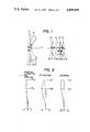
- FIG. 1 is a cross-sectional view showing the construction of the lens system according to the present invention
- a wide angle photographic lens system in accordance with the present invention comprises six lens components, in the order from the object side, a first lens component L1 which is a positive lens having its more convex surface facing the object side, a second lens component L2 which is a negative meniscus lens having its convex surface facing the object side, a third lens component L3 which is a biconvex lens having its more convex surface facing the object side, a fourth lens component L4 which is a biconcave lens, a fifth lens component L5 which is a positive meniscus lens having its convex surface facing the image side, and a sixth lens component L6 which is a biconvex lens.
- a diaphragm is positioned between the third and fourth lens components. This lens system satisfies the following conditions:
- f is the total focal length of the lens system
- f 1 and f 2 are the focal lengths of the first and the second lens components, respectively
- f 12 is the combined focal length of the first and second lens components
- r 4 is the curvature radius of the surface of the second lens component which faces the image side
- d 1 and d 3 are the center thicknesses of the first and the second lens components respectively
- d 2 and d 4 are the air spaces between the first and second lens components and between the second and third lens components, respectively.
- Condition (1) is intended to minimize the aperture of the foremost lens component where the diaphragm is disposed between the third and the fourth lens components. If
- condition (2) is to bring about a greater advantage where the aperture of the foremost lens component is minimized with condition (1) being satisfied.
- a greater advantage is obtained as the focal length f 1 of the first lens component is greater, or the absolute value
- is restricted to condition (1), a greater value of f 1 /
- the lower limit of condition (2) is exceeded, the resulting disadvantage is that the aperture of the foremost lens component is reduced.
- Condition (3) serves to bring about good correction of the various aberrations while increasing the back focal distance to 1.3f or greater. Also, the aperture of the foremost lens component is reduced so that a compact and light weight lens system is obtained.
- the inter-vertex distance d 4 between the second lens component and the third lens component should preferably be great in order to correct the aberrations or to increase the back focal distance, though this would offer the disadvantage that the aperture of the foremost lens component is increased. Also, a smaller value of (d 1 +d 2 +d 3 ) is advantageous to reduce the aperture of the foremost lens component and useful to realize a compact and light weight lens system.
- Condition (4) is intended to restrict the curvature radius of the surface of the second lens component facing the image side and provide a back focal distance of 1.3f or greater, whereby the bending of the image plane and the coma which tend to occur in said surface may be kept within reasonable bounds. If the upper limit of this condition is exceeded, the result would be a back focal distance of less than 1.3f and an increase in the aperture of the foremost lens component. Conversely, if the lower limit of this condition were to be exceeded to intensify the curvature of the surface under consideration, it would be difficult to correct the bending of the image plane and the coma occurring and this surface.
- r, d, nd and ⁇ d represent the curvature radius of each refracting surface, the center thickness of each lens component or the air space between adjacent lens components, the refractive index of each lens component, and the Abbe number of each lens component, the subscripts representing the order from the object side.
- the aperture of the foremost lens component is smaller by about 19% than in the lens system of the aforementioned Japanese patent publication No. 26133/1963, and yet the performance is much improved even in terms of aberrations.
- Such a reduced aperture of the foremost lens component affords the realization of compactness and light weight of the entire lens system. Also, there is prevention of the interception of the marginal rays or the reduction in quantity of the marginal light which would be caused by a filter being mounted on the lens system.
Landscapes
- Physics & Mathematics (AREA)
- General Physics & Mathematics (AREA)
- Optics & Photonics (AREA)
- Lenses (AREA)
Abstract
A wide angle photographic lens system comprises, in the order from the object side, a first lens component which is a positive lens having its more convex surface facing the object side, a second lens component which is a negative meniscus lens having its convex surface facing the object side, a third lens component which is a biconvex lens having its more convex surface facing the object side, a diaphragm, a fourth lens component which is a biconcave lens, a fifth lens component which is a positive meniscus lens having its convex surface facing the image side, and a sixth lens component which is a biconvex lens. Four distinctive optical conditions are characteristic of the lens system.
Description
1. Field of the Invention
This invention relates to a wide angle photographic lens having an aperture ratio of 1:3.5 and an angle of view of 75° which is compact and light in weight and which comprises only six lens components and yet has aberrations which are well corrected.
2. Description of the Prior Art
A lens of the type under consideration is disclosed in Japanese patent publication No. 26133/1963. The purpose of the present invention is to make a lens of this type more compact and to better correct the various aberrations thereof to thereby improve its performance. Usually, in a wide angle lens, it is advantageous to dispose a diaphragm as close as possible to the foremost lens component or to make the focal length of the front divergent lens group as small as possible in order that the entire lens may be compact with the aperture of the foremost lens component reduced.
In conventional lenses of this type, which comprise six lens components, the diaphragm is disposed between the second and third lens components so that the diaphragm may be as close as possible to the foremost lens component, or the diaphragm is disposed between the third and fourth lens components while the negative combined focal length of the first and second lens components is reduced to thereby reduce the aperture of the foremost lens component. However, in the former example wherein the diaphragm is disposed between the second and the third lens components, the lens components behind the diaphragm have been subjected to overstrain, and this has led to difficulties in terms of aberrations when the number of lens components is restricted to six lens components in six groups. In the latter example wherein the aperture of the foremost lens component is reduced with the negative combined focal length of the first and second lens components being minimized, the Petzval sum goes in the negative direction, and unavoidably this must be compensated for by thickening the lenses in the front group. As a result, it is difficult to achieve a lens which is light in weight. Also, the radius of curvature of the surface of the second lens component which faces the image side becomes necessarily small to permit bending of the image plane and coma to occur in such surface and thus aberrations are encountered.
It is an object of the present invention to provide a wide angle photographic lens which is made compact by reducing the aperture of the foremost lens component and in which the various aberrations are well corrected to enhance the performance of the lens.
To achieve such an object, the wide angle photographic lens system according to the present invention comprises, in the order from the object side, a first lens component which is a positive lens having its more convex surface facing the object side, a second lens component which is a negative meniscus lens having its convex surface facing the object side, a third lens component which is a biconvex lens having its more convex surface facing the object side, a diaphragm, a fourth lens component which is a biconcave lens, a fifth lens component which is a positive meniscus lens having its convex surface facing the image side, and a sixth lens component which is a biconvex lens. The lens system satisfies certain conditions which will be described hereinafter.
The invention will become more fully apparent from the following detailed description thereof taken in conjunction with the accompanying drawings.
FIG. 1 is a cross-sectional view showing the construction of the lens system according to the present invention;
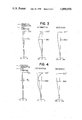
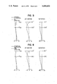
FIGS. 2 - 6 are graphs illustrating the corrections of the various aberrations in Examples 1 to 5, for the total focal length f=100.
Referring to FIG. 1, a wide angle photographic lens system in accordance with the present invention comprises six lens components, in the order from the object side, a first lens component L1 which is a positive lens having its more convex surface facing the object side, a second lens component L2 which is a negative meniscus lens having its convex surface facing the object side, a third lens component L3 which is a biconvex lens having its more convex surface facing the object side, a fourth lens component L4 which is a biconcave lens, a fifth lens component L5 which is a positive meniscus lens having its convex surface facing the image side, and a sixth lens component L6 which is a biconvex lens. A diaphragm is positioned between the third and fourth lens components. This lens system satisfies the following conditions:
1.5f < |f.sub.12 | < 1.75f (1)
5.0 < f.sub.1 /|f.sub.2 | < 8.0 (2)
0.1 < (d.sub.1 + d.sub.2 + d.sub.3)/d.sub.4 < 0.35 (3)
0.5f < r.sub.4 < 0.6f (4)
where f is the total focal length of the lens system, f1 and f2 are the focal lengths of the first and the second lens components, respectively, f12 is the combined focal length of the first and second lens components, r4 is the curvature radius of the surface of the second lens component which faces the image side, d1 and d3 are the center thicknesses of the first and the second lens components respectively, and d2 and d4 are the air spaces between the first and second lens components and between the second and third lens components, respectively.
Each of the above conditions will now be considered. Condition (1) is intended to minimize the aperture of the foremost lens component where the diaphragm is disposed between the third and the fourth lens components. If |f12 | is greater than its upper limit, the aperture of the foremost lens will increase and it will be difficult to make the entire lens system compact where the diaphragm is disposed between the third and the fourth lens components If, conversely, |f12 | is smaller than its lower limit, a greater advantage will be experienced reducing the aperture of the foremost lens component but, as already described, the Petzval sum will go in the negative direction and this will have to be correct by thickening the lens components before the diaphragm, which in turn will lead to difficulty in making the entire system compact and light in weight, with the further result that the lower limit of condition (4) is exceeded, whereby inducing the bending of the image plane and aggravation of coma.
The purpose of condition (2) is to bring about a greater advantage where the aperture of the foremost lens component is minimized with condition (1) being satisfied. In other words, where the location of the diaphragm is set up, a greater advantage is obtained as the focal length f1 of the first lens component is greater, or the absolute value |f2 | of the focal length of the second lens component is smaller, and thus, the greater value of f1 /|f2 |, the better the result. Where |f12 | is restricted to condition (1), a greater value of f1 /|f2 | will result in a relatively small value of |f2 | and an increased power of the second lens component, and therefore, the upper limit of condition (2) is exceeded to increase the power of the second lens component to inadequately correct the various aberrations. Conversely, when the lower limit of condition (2) is exceeded, the resulting disadvantage is that the aperture of the foremost lens component is reduced.
Condition (3) serves to bring about good correction of the various aberrations while increasing the back focal distance to 1.3f or greater. Also, the aperture of the foremost lens component is reduced so that a compact and light weight lens system is obtained.
The inter-vertex distance d4 between the second lens component and the third lens component should preferably be great in order to correct the aberrations or to increase the back focal distance, though this would offer the disadvantage that the aperture of the foremost lens component is increased. Also, a smaller value of (d1 +d2 +d3) is advantageous to reduce the aperture of the foremost lens component and useful to realize a compact and light weight lens system. Where the advantage of compactness and light weight is brought about by decreasing (d1 +d2 +d3), it is possible to increase the back focal distance and facilitate the correction of the aberrations by increasing d4 correspondingly, but if the lower limit of condition (3) is exceeded to increase the difference between d4 and (d1 +d2 +d3), an adverse result will occur in that the aperture of the foremost lens component is increased. Conversely, within such range that the back focal length of 1.3f or greater is properly attained while the correction of the aberrations is ensured, it is also possible to minimize d4 to thereby bring about the advantage of reducing the aperture of the foremost lens component. However, if the upper limit of condition (3) is exceeded, difficulties will be encountered in realizing compactness and light weight.
Condition (4) is intended to restrict the curvature radius of the surface of the second lens component facing the image side and provide a back focal distance of 1.3f or greater, whereby the bending of the image plane and the coma which tend to occur in said surface may be kept within reasonable bounds. If the upper limit of this condition is exceeded, the result would be a back focal distance of less than 1.3f and an increase in the aperture of the foremost lens component. Conversely, if the lower limit of this condition were to be exceeded to intensify the curvature of the surface under consideration, it would be difficult to correct the bending of the image plane and the coma occurring and this surface.
Preferred examples of the lens system according to the present invention will be shown below, in which r, d, nd and νd, respectively, represent the curvature radius of each refracting surface, the center thickness of each lens component or the air space between adjacent lens components, the refractive index of each lens component, and the Abbe number of each lens component, the subscripts representing the order from the object side.
______________________________________ total focal length f = 100.0 aperture ratio 1:3.5 angle ofview 2 ω= 74.2° r.sub.1 = 386.719 d.sub.1 = 9.199 nd.sub.1 = 1.62374 γd.sub.1 = 47.0 r.sub.2 = 1871.551 d.sub.2 = 0.343 r.sub.3 = 167.545 d.sub.3 = 4.909 nd.sub.2 = 1.62041 γd.sub.2 = 60.3 r.sub.4 = 55.370 d.sub.4 = 93.708 r.sub.5 = 85.216 d.sub.5 = 9.611 nd.sub.3 = 1.70154 γd.sub.3 = 41.1 r.sub.6 = -197.175 d.sub.6 = 19.222 r.sub.7 = -77.840 d.sub.7 = 15.446 nd.sub.4 = 1.7552 γd.sub.4 = 27.5 r.sub.8 = 120.630 d.sub.8 = 3.776 r.sub. 9 = -265.822 d.sub.9 = 9.268 nd.sub.5 = 1.62041 γd.sub.5 = 60.3 r.sub.10 = -64.116 d.sub.10 = 0.343 r.sub.11 = 285.350 d.sub.11 = 8.581 nd.sub.6 = 1.58913 γd.sub.6 = 61.2 r.sub.12 = -150.156 back focal distance = 133.975 f.sub.12 = -167.233 ______________________________________
______________________________________
total focal length f = 100.0  aperture ratio 1:3.5
angle of view 2ω = 74.2°
r.sub.1 =
     897.870
                d.sub.1 =
                       8.026
                            nd.sub.1 = 1.62374
                                       γd.sub.1 = 47.0
r.sub.2 =
     -3310.382
                d.sub.2 =
                       0.343
r.sub.3 =
     136.893
                d.sub.3 =
                       4.253
                            nd.sub.2 = 1.62041
                                       γd.sub.2 = 60.3
r.sub.4 =
     53.140
                d.sub.4 =
                       93.631
r.sub.5 =
     84.333
                d.sub.5 =
                       9.603
                            nd.sub.3 = 1.70154
                                       γd.sub.3 = 41.1
r.sub.6 =
     -174.397
                d.sub.6 =
                       19.206
r.sub.7 =
     -76.308
                d.sub.7 =
                       15.434
                            nd.sub.4 = 1.7552
                                       γd.sub.4 = 27.5
r.sub.8 =
     115.280
                d.sub.8 =
                       3.773
r.sub.9 =
     -306.739
                d.sub.9 =
                       9.260
                            nd.sub.5 = 1.62041
                                       γ d.sub.5 = 60.3
r.sub.10 =
     -64.352
                d.sub.10 =
                       0.343
r.sub.11 =
     287.241
                d.sub.11 =
                       8.574
                            nd.sub.6 = 1.58913
                                       γd.sub.6 = 61.2
r.sub.12 =
     -166.025
        back focal distance = 132.016
        f.sub.12 = -164.787
______________________________________
______________________________________
total focal length f = 100.0  aperture ratio 1:3.5
angle of view 2ω = 74.2°
r.sub.1 =
     367.133
               d.sub.1 =
                      12.226
                            nd.sub.1 = 1.60323
                                       γd.sub.1 = 42.5
r.sub.2 =
     3881.119
               d.sub.2 =
                      2.448
r.sub.3 =
     180.070
               d.sub.3 =
                      5.594 nd.sub.2 = 1.58913
                                       γd.sub.2 = 61.2
r.sub.4 =
     51.923
               d.sub.4 =
                      80.420
r.sub.5 =
     90.210
               d.sub.5 =
                      16.434
                            nd.sub.3 = 1.72342
                                       γd.sub.3 = 38.0
r.sub.6 =
     -202.098
               d.sub.6 =
                      18.531
r.sub.7 =
     -81.119
               d.sub.7 =
                      12.238
                            nd.sub.4 = 1.80518
                                       γd.sub.4 = 25.5
r.sub.8 =
     128.671
               d.sub.8 =
                      6.643
r.sub.9 =
     -699.301
               d.sub.9 =
                      12.937
                            nd.sub.5 = 1.713
                                       γd.sub.5 = 53.9
r.sub.10 =
     -70.175
               d.sub.10 =
                      1.049
r.sub.11 =
     262.238
               d.sub.11 =
                      9.091 nd.sub.6 = 1.5168
                                       γd.sub.6 = 64.2
r.sub.12 =
     174.275
        back focal distance = 132.455
        f.sub.12 = -160.839
______________________________________
______________________________________
total focal length f = 100.0  aperture ratio 1:3.5
angle of view ω2 = 74.2°
r.sub.1 =
     349.650
               d.sub.1 =
                      13.986
                            nd.sub.1 = 1.60323
                                       γd.sub.1 = 42.5
r.sub.2 =
     3461.538
               d.sub.2 =
                      2.448
r.sub.3 =
     171.329
               d.sub.3 =
                      5.594 nd.sub.2 = 1.62041
                                       γd.sub.2 = 60.3
r.sub.4 =
     52.448
               d.sub.4 =
                      80.420
r.sub.5 =
     87.413
               d.sub.5 =
                      11.189
                            nd.sub.3 = 1.172342
                                       γd.sub.3 = 38.0
r.sub.6 =
     -228.479
               d.sub.6 =
                      18.182
r.sub.7 =
     -85.564
               d.sub.7 =
                      13.986
                            nd.sub.4 = 1.78470
                                       γd.sub.4 = 26.1
r.sub.8 =
     117.626
               d.sub.8 =
                      6.643
r.sub.9 =
     -699.301
               d.sub.9 =
                      11.888
                            nd.sub.5 = 1.69680
                                       γd.sub.5 = 55.6
r.sub.10 =
     -68.706
               d.sub.10 =
                      1.049
r.sub.11 =
     227.273
               d.sub.11 =
                      9.091 nd.sub.6 = 1.48749
                                       γd.sub.6 = 70.0
r.sub.12 =
     -182.003
        back focal distance = 134.343
        f.sub.12 = -159.091
______________________________________
______________________________________
total focal length f = 100.0  aperture ratio 1:3.5
angle of view 2ω = 74.2°
r.sub.1 =
     356.822
               d.sub.1 =
                      10.490
                            nd.sub.1 = 1.62374
                                       γd.sub.1 = 47.0
r.sub.2 =
     2169.231
               d.sub.2 =
                      0.350
r.sub.3 =
     199.301
               d.sub.3 =
                      5.594 nd.sub.2 = 1.62041
                                       γd.sub.2 = 60.3
r.sub.4 =
     55.245
               d.sub.4 =
                      95.455
r.sub.5 =
     84.965
               d.sub.5 =
                      9.790 nd.sub.3 = 1.70154
                                       γd.sub.3 = 41.1
r.sub.6 =
     -187.203
               d.sub.6 =
                      19.580
r.sub.7 =
     -75.150
               d.sub.7 =
                      15.734
                            nd.sub.4 = 1.7552
                                       γd.sub.4 = 27.5
r.sub.8 =
     122.028
               d.sub.8 =
                      3.846
r.sub.9 =
     -314.685
               d.sub.9 =
                      9.441 nd.sub.5 = 1.62041
                                       γd.sub. 5 = 60.3
r.sub.10 =
     -63.217
               d.sub.10 =
                      0.350
r.sub.11 =
     286.713
               d.sub.11 =
                      8.741 nd.sub.6 = 1.58913
                                       γd.sub.6 = 61.2
r.sub.12 =
     -174.126
        back focal distance = 137.350
        f.sub.12 = -156.643
______________________________________
According to the present invention, as seen in FIGS. 2 - 6, the aperture of the foremost lens component is smaller by about 19% than in the lens system of the aforementioned Japanese patent publication No. 26133/1963, and yet the performance is much improved even in terms of aberrations. Such a reduced aperture of the foremost lens component affords the realization of compactness and light weight of the entire lens system. Also, there is prevention of the interception of the marginal rays or the reduction in quantity of the marginal light which would be caused by a filter being mounted on the lens system.
It is believed that the advantages and improved results furnished by the improved wide angle lens systems of the invention will be apparent from the foregoing description of several preferred embodiments of the invention. Various changes and modifications may be made without departing from the spirit and scope of the invention as sought to be defined in the following claims.
Claims (6)
1. A wide angle photographic lens system comprising in the order from the object side, a first lens component which is a positive lens having its more convex surface facing the object side, a second lens component which is a negative meniscus lens having its convex surface facing the object side, a third lens component which is a biconvex lens having its more convex surface facing the object side, a diaphragm, a fourth lens component which is a biconcave lens, a fifth lens component which is a positive meniscus lens having its convex surface facing the image side, and a sixth lens component which is a biconvex lens, said lens system satisfying the following conditions:
1.5f < |f.sub.12 | < 1.75f (1)
5.0 <f.sub.1 /|f.sub.2 | < 8.0 (2)
0.1 <d.sub.1 + d.sub.2 + d.sub.3 /d.sub.4 < 0.35 (3)
0.5f < r.sub.4 < 0.6f (4)
where f is the total focal length of the lens system, f1 and f2 are the focal lengths of the first and the second lens components, respectively, f12 is the combined focal length of the first and second lens components, r4 is the curvature radius of the surface of the second lens component which faces the image side, d1 and d3 are the center thicknesses of the first and the second lens components, respectively, and d2 and d4 are the air spaces between the first and second lens components and between the second and third lens components, respectively.
2. A lens system according to claim 1, wherein the numerical data are as shown in the following table:
______________________________________
           Thicknesses
           and        Refractive   Abbe
Radii      air spaces indexes      numbers
______________________________________
r.sub.1 =
     386.719
               d.sub.1 =
                      9.199 nd.sub.1 = 1.62374
                                       γd.sub.1 = 47.0
r.sub.2 =
     1871.551
               d.sub.2 =
                      0.343
r.sub.3 =
     167.545
               d.sub.3 =
                      4.909 nd.sub.2 = 1.62041
                                       γd.sub.2 = 60.3
r.sub.4 =
     55.370
               d.sub.4 =
                      93.708
r.sub.5 =
     85.216
               d.sub.5 =
                      9.611 nd.sub.3 = 1.70154
                                       γd.sub.3 = 41.1
r.sub.6 =
     -197.175
               d.sub.6 =
                      19.222
r.sub.7 =
     -77.840
               d.sub.7 =
                      15.446
                            nd.sub.4 = 1.7552
                                       γd.sub.4 = 27.5
r.sub.8 =
     120.630
               d.sub.8 =
                      3.776
r.sub.9 =
     -265.822
               d.sub.9 =
                      9.268 nd.sub.5 = 1.62041
                                       γd.sub.5 = 60.3
r.sub. 10 =
     -64.116
               d.sub.10 =
                      0.343
r.sub.11 =
     285.350
               d.sub.11 =
                      8.581 nd.sub.6 = 1.58913
                                       γd.sub.6 = 61.2
r.sub.12 =
     -150.156
______________________________________
3. A lens system according to claim 1, wherein the numerical data are as shown in the following table:
______________________________________
            Thicknesses
            and       Refractive   Abbe
Radii       air spaces
                      indexes      Numbers
______________________________________
r.sub.1 =
     897.870
                d.sub.1 =
                       8.026
                            nd.sub.1 = 1.62374
                                       γd.sub.1 = 47.0
r.sub.2 =
     -3310.382
                d.sub.2 =
                       0.343
r.sub.3 =
     136.893
                d.sub.3 =
                       4.253
                            nd.sub.2 = 1.62041
                                       γd.sub.2 = 60.3
r.sub.4 =
     53.140
                d.sub.4 =
                       93.631
r.sub.5 =
     84.333
                d.sub.5 =
                       9.603
                            nd.sub.3 = 1.70154
                                       γd.sub.3 = 41.1
r.sub.6 =
     -174.397
                d.sub.6 =
                       19.206
r.sub.7 =
     -76.308
                d.sub.7 =
                       15.434
                            nd.sub.4 = 1.7552
                                       γd.sub.4 = 27.5
r.sub.8 =
     115.280
                d.sub.8 =
                       3.773
r.sub.9 =
     -306.739
                d.sub.9 =
                       9.260
                            nd.sub.5 = 1.62041
                                       γd.sub.5  = 60.3
r.sub.10 =
     -64.352
                d.sub.10 =
                       0.343
r.sub.11 =
     287.241
                d.sub.11 =
                       8.574
                            nd.sub.6 = 1.58913
                                       γd.sub.6 = 61.2
r.sub.12 =
     -166.025
______________________________________
4. A lens system according to claim 1, wherein the numerical data are as shown in the following table:
______________________________________
           Thicknesses
           and        Refractive   Abbe
Radii      air spaces indexes      numbers
______________________________________
r.sub.1 =
     367.133
               d.sub.1 =
                      12.226
                            nd.sub.1 = 1.60323
                                       γd.sub.1 = 42.5
r.sub.2 =
     3881.119
               d.sub.2 =
                      2.448
r.sub.3 =
     180.070
               d.sub.3 =
                      5.594 nd.sub.2 = 1.58913
                                       γd.sub.2 = 61.2
r.sub.4 =
     51.923
               d.sub.4 =
                      80.420
r.sub.5 =
     90.210
               d.sub.5 =
                      16.434
                            nd.sub.3 = 1.72342
                                       γd.sub.3 = 38.0
r.sub.6 =
     -202.098
               d.sub.6 =
                      18.531
r.sub.7 =
     -81.119
               d.sub.7 =
                      12.238
                            nd.sub.4 = 1.80518
                                       γd.sub.4 = 25.5
r.sub.8 =
     128.671
               d.sub.8 =
                      6.643
r.sub.9 =
     -699.301
               d.sub.9 =
                      12.937
                            nd.sub.5 = 1.713
                                       γd.sub.5 =  53.9
r.sub.10 =
     -70.175
               d.sub.10 =
                      1.049
r.sub.11 =
     262.238
               d.sub.11 =
                      9.091 nd.sub.6 = 1.5168
                                       γd.sub.6 = 64.2
r.sub.12 =
     174.275
______________________________________
5. A lens system according to claim 1, wherein the numerical data are as shown in the following table:
______________________________________
           Thicknesses
           and        Refractive   Abbe
Radii      air spaces indexes      numbers
______________________________________
r.sub.1 =
     349.650
               d.sub.1 =
                      13.986
                            nd.sub.1 = 1.60323
                                       γd.sub.1 = 42.5
r.sub.2 =
     3461.538
               d.sub.2 =
                      2.448
r.sub.3 =
     171.329
               d.sub.3 =
                      5.594 nd.sub.2 = 1.62041
                                       γd.sub.1 = 60.3
r.sub.4 =
     52.448
               d.sub.4 =
                      80.420
r.sub.5 =
     87.413
               d.sub.5 =
                      11.189
                            nd.sub.3 = 1.72342
                                       γd.sub.3 = 38.0
r.sub.6 =
     -228.479
               d.sub.6 =
                      18.182
r.sub.7 =
     -85.564
               d.sub.7 =
                      13.986
                            nd.sub.4 = 1.78470
                                       γd.sub.4 = 26.1
r.sub.8 =
     117.626
               d.sub.8 =
                      6.643
r.sub.9 =
     -699.301
               d.sub.9 =
                      11.888
                            nd.sub.5 = 1.69680
                                       γd.sub.5  = 55.6
r.sub.10 =
     -68.706
               d.sub.10 =
                      1.049
r.sub.11 =
     227.273
               d.sub.11 =
                      9.091 nd.sub.6 = 1.48749
                                       γd.sub.6 = 70.0
r.sub.12 =
     -182,003
______________________________________
6. A lens system according to claim 1, wherein the numerical data are as shown in the following table:
______________________________________
           Thicknesses
           and        Refractive   Abbe
Radii      air spaces indexes      numbers
______________________________________
r.sub.1 =
     356.822
               d.sub.1 =
                      10.490
                            nd.sub.1 = 1.62374
                                       γd.sub.1 = 47.0
r.sub.2 =
     2169.231
               d.sub.2 =
                      0.350
r.sub.3 =
     199.301
               d.sub.3 =
                      5.594 nd.sub.2 = 1.62041
                                       γd.sub.2 = 60.3
r.sub.4 =
     55.245
               d.sub.4 =
                      95.455
r.sub.5 =
     84.965
               d.sub.5 =
                      9.790 nd.sub.3 =1.70154
                                       γd.sub.3 = 41.1
r.sub.6 =
     -187.203
               d.sub.6 =
                      19.580
r.sub.7 =
     -75.150
               d.sub.7 =
                      15.734
                            nd.sub.4 = 1.7552
                                       γd.sub.4 = 27.5
r.sub.8 =
     122.028
               d.sub.8 =
                      3.846
r.sub.9 =
     -314.685
               d.sub.9 =
                      9.441 nd.sub.5 = 1.62041
                                       γd.sub.5 =  60.3
r.sub.10 =
     -63.217
               d.sub.10 =
                      0.350
r.sub.11 =
     286.713
               d.sub.11 =
                      8.741 nd.sub.6 = 1.58913
                                       γd.sub.6 = 61.2
r.sub.12 =
     -174.126
______________________________________
Applications Claiming Priority (2)
| Application Number | Priority Date | Filing Date | Title |
|---|---|---|---|
| JP51-11566 | 1976-02-05 | ||
| JP51011566A JPS6035648B2 (en) | 1976-02-05 | 1976-02-05 | wide angle photo lens |
Publications (1)
| Publication Number | Publication Date |
|---|---|
| US4099850A true US4099850A (en) | 1978-07-11 |
Family
ID=11781474
Family Applications (1)
| Application Number | Title | Priority Date | Filing Date |
|---|---|---|---|
| US05/765,605 Expired - Lifetime US4099850A (en) | 1976-02-05 | 1977-02-04 | Wide angle photographic lens |
Country Status (3)
| Country | Link |
|---|---|
| US (1) | US4099850A (en) |
| JP (1) | JPS6035648B2 (en) |
| DE (1) | DE2704725C3 (en) |
Cited By (8)
| Publication number | Priority date | Publication date | Assignee | Title |
|---|---|---|---|---|
| US4235520A (en) * | 1977-06-10 | 1980-11-25 | Olympus Optical Co., Ltd. | Wide-angle retrofocus lens system |
| US4333714A (en) * | 1978-09-11 | 1982-06-08 | Vivitar Corporation | Compact wide angle lens |
| EP0217526A1 (en) * | 1985-08-26 | 1987-04-08 | Minnesota Mining And Manufacturing Company | Ultra wide angle micrographic lens |
| US4810070A (en) * | 1985-08-30 | 1989-03-07 | Canon Kabushiki Kaisha | Lens system having a good image performance for white light |
| US5042929A (en) * | 1989-03-23 | 1991-08-27 | Matsushita Electric Industrial Co., Ltd. | Projection lens and projection system |
| US5557473A (en) * | 1993-04-13 | 1996-09-17 | Nikon Corporation | Wide angle lens |
| US5745307A (en) * | 1995-12-22 | 1998-04-28 | Eastman Kodak Company | Cluster lens system such as for use in photographic printers |
| NL1003870C2 (en) * | 1995-08-25 | 1998-12-08 | Asahi Optical Co Ltd | Fast wide angle lens system. |
Citations (2)
| Publication number | Priority date | Publication date | Assignee | Title |
|---|---|---|---|---|
| FR83408E (en) * | 1962-12-18 | 1964-08-07 | Zeiss Carl Fa | Photographic lens |
| US3955883A (en) * | 1974-03-07 | 1976-05-11 | Asahi Kogaku Kogyo Kabushiki Kaisha | Wide angle photographic lens |
Family Cites Families (1)
| Publication number | Priority date | Publication date | Assignee | Title |
|---|---|---|---|---|
| DE1250152B (en) * | 1967-09-14 |
-
1976
- 1976-02-05 JP JP51011566A patent/JPS6035648B2/en not_active Expired
-
1977
- 1977-02-04 DE DE2704725A patent/DE2704725C3/en not_active Expired
- 1977-02-04 US US05/765,605 patent/US4099850A/en not_active Expired - Lifetime
Patent Citations (2)
| Publication number | Priority date | Publication date | Assignee | Title |
|---|---|---|---|---|
| FR83408E (en) * | 1962-12-18 | 1964-08-07 | Zeiss Carl Fa | Photographic lens |
| US3955883A (en) * | 1974-03-07 | 1976-05-11 | Asahi Kogaku Kogyo Kabushiki Kaisha | Wide angle photographic lens |
Cited By (8)
| Publication number | Priority date | Publication date | Assignee | Title |
|---|---|---|---|---|
| US4235520A (en) * | 1977-06-10 | 1980-11-25 | Olympus Optical Co., Ltd. | Wide-angle retrofocus lens system |
| US4333714A (en) * | 1978-09-11 | 1982-06-08 | Vivitar Corporation | Compact wide angle lens |
| EP0217526A1 (en) * | 1985-08-26 | 1987-04-08 | Minnesota Mining And Manufacturing Company | Ultra wide angle micrographic lens |
| US4810070A (en) * | 1985-08-30 | 1989-03-07 | Canon Kabushiki Kaisha | Lens system having a good image performance for white light |
| US5042929A (en) * | 1989-03-23 | 1991-08-27 | Matsushita Electric Industrial Co., Ltd. | Projection lens and projection system |
| US5557473A (en) * | 1993-04-13 | 1996-09-17 | Nikon Corporation | Wide angle lens |
| NL1003870C2 (en) * | 1995-08-25 | 1998-12-08 | Asahi Optical Co Ltd | Fast wide angle lens system. |
| US5745307A (en) * | 1995-12-22 | 1998-04-28 | Eastman Kodak Company | Cluster lens system such as for use in photographic printers |
Also Published As
| Publication number | Publication date |
|---|---|
| JPS6035648B2 (en) | 1985-08-15 |
| DE2704725B2 (en) | 1979-05-03 |
| JPS5295219A (en) | 1977-08-10 |
| DE2704725C3 (en) | 1980-01-03 |
| DE2704725A1 (en) | 1977-08-11 |
Similar Documents
| Publication | Publication Date | Title |
|---|---|---|
| US5309285A (en) | Zoom lens system for use with a compact camera | |
| US4465345A (en) | Small-size telescopic lens | |
| US5381268A (en) | Compact wide angle zoom lens | |
| US3936153A (en) | Retrofocus type objective lens system | |
| US5636067A (en) | Taking lens system | |
| JPS6119008B2 (en) | ||
| US4514052A (en) | High speed objective lens system with an aspheric surface | |
| JPS6155087B2 (en) | ||
| US5625497A (en) | Retrofocus type standard lens and wide angle lens | |
| US4099850A (en) | Wide angle photographic lens | |
| US4354743A (en) | Attachment lens system | |
| US4643536A (en) | Rear conversion lens | |
| US4139265A (en) | Modified gauss type photographic lens | |
| US4176915A (en) | Wide angle lens | |
| US4556295A (en) | Ultracompact telephoto lens | |
| US4537476A (en) | Retro-focus type wide angle lens | |
| US4435049A (en) | Telephoto lens system | |
| US4950055A (en) | Retrofocus type wide angle lens | |
| US4348085A (en) | Inverted telephoto type wide angle lens | |
| US4143945A (en) | Small retro-focus wide angle photographic lens system | |
| US4019810A (en) | Photographic wide angle lens | |
| US4212517A (en) | Photographic lens system | |
| US4206976A (en) | Compact telephoto lens | |
| US4033675A (en) | Wide angle lens | |
| US4163603A (en) | Wide-angle photograhic objective |
Legal Events
| Date | Code | Title | Description |
|---|---|---|---|
| AS | Assignment |
Owner name: NIKON CORPORATION, 2-3, MARUNOUCHI 3-CHOME, CHIYOD Free format text: CHANGE OF NAME;ASSIGNOR:NIPPON KOGAKU, K.K.;REEL/FRAME:004935/0584 |