US3990302A - Automotive ignition analyzer with cylinder of interest display - Google Patents
Automotive ignition analyzer with cylinder of interest display Download PDFInfo
- Publication number
- US3990302A US3990302A US05/635,738 US63573875A US3990302A US 3990302 A US3990302 A US 3990302A US 63573875 A US63573875 A US 63573875A US 3990302 A US3990302 A US 3990302A
- Authority
- US
- United States
- Prior art keywords
- cylinder
- ignition
- interest
- switch
- analyzer
- Prior art date
- Legal status (The legal status is an assumption and is not a legal conclusion. Google has not performed a legal analysis and makes no representation as to the accuracy of the status listed.)
- Expired - Lifetime
Links
- 238000010304 firing Methods 0.000 claims description 47
- 239000000523 sample Substances 0.000 claims description 15
- 230000002265 prevention Effects 0.000 claims description 11
- 238000002485 combustion reaction Methods 0.000 claims description 9
- 230000004044 response Effects 0.000 claims description 5
- 230000001360 synchronised effect Effects 0.000 claims description 4
- 230000007246 mechanism Effects 0.000 abstract description 4
- 238000007493 shaping process Methods 0.000 description 7
- 238000006073 displacement reaction Methods 0.000 description 6
- 230000000994 depressogenic effect Effects 0.000 description 4
- 230000004913 activation Effects 0.000 description 2
- 230000008859 change Effects 0.000 description 2
- 238000000926 separation method Methods 0.000 description 2
- 230000001934 delay Effects 0.000 description 1
- 230000000694 effects Effects 0.000 description 1
- 238000001914 filtration Methods 0.000 description 1
- 230000000977 initiatory effect Effects 0.000 description 1
- 238000000034 method Methods 0.000 description 1
- 238000012986 modification Methods 0.000 description 1
- 230000004048 modification Effects 0.000 description 1
- 238000012544 monitoring process Methods 0.000 description 1
Images


Classifications
-
- F—MECHANICAL ENGINEERING; LIGHTING; HEATING; WEAPONS; BLASTING
- F02—COMBUSTION ENGINES; HOT-GAS OR COMBUSTION-PRODUCT ENGINE PLANTS
- F02P—IGNITION, OTHER THAN COMPRESSION IGNITION, FOR INTERNAL-COMBUSTION ENGINES; TESTING OF IGNITION TIMING IN COMPRESSION-IGNITION ENGINES
- F02P17/00—Testing of ignition installations, e.g. in combination with adjusting; Testing of ignition timing in compression-ignition engines
- F02P17/02—Checking or adjusting ignition timing
- F02P17/04—Checking or adjusting ignition timing dynamically
- F02P17/08—Checking or adjusting ignition timing dynamically using a cathode-ray oscilloscope
-
- G—PHYSICS
- G01—MEASURING; TESTING
- G01M—TESTING STATIC OR DYNAMIC BALANCE OF MACHINES OR STRUCTURES; TESTING OF STRUCTURES OR APPARATUS, NOT OTHERWISE PROVIDED FOR
- G01M15/00—Testing of engines
- G01M15/04—Testing internal-combustion engines
- G01M15/042—Testing internal-combustion engines by monitoring a single specific parameter not covered by groups G01M15/06 - G01M15/12
- G01M15/044—Testing internal-combustion engines by monitoring a single specific parameter not covered by groups G01M15/06 - G01M15/12 by monitoring power, e.g. by operating the engine with one of the ignitions interrupted; by using acceleration tests
Definitions
- the instant invention relates to ignition analyzers which display signal information related to the operation of the ignition systems of multi-cylinder internal combustion engines, such as automobile engines, on an oscilloscope for use by a mechanic in analyzing engine performance.
- Ignition analyzers utilizing oscilloscope displays are well known in the art and well accepted by both the professional and amateur mechanic as instruments for providing detailed information regarding the performance of a particular internal combustion engine, usually an automobile.
- the most basic display format utilizes electrical signals related to the voltage impressed across each spark plug of the internal combustion engine and displays these signals throughout one engine cycle, that is, through one cycle of firing of each spark plug. This is called the parade mode of display.
- a magnetic or capacitive probe is connected to the secondary circuit of the ignition system at the high tension wire leading between the coil and distributor. The signal developed thereby is then suitably amplified and provided to the vertical input of an oscilloscope to drive the oscilloscopic trace vertially.
- the horizontal input of the oscilloscope is provided by a ramp generator which is synchronized with the engine cycle, that is, the ramp moves the oscilloscopic trace across the face of the display once per engine cycle. This is normally accomplished by synchronizing the beginning or end of the ramp to the firing of a particular cylinder, conveniently called cylinder No. 1.
- the major drawback to the parade mode of display is that the horizontal width of the oscilloscopes is in practice insufficient to show all the cylinders of a multi-cylinder engine in sufficient detail to provide all the required information.
- the ramp moves the trace through its horizontal range of motion once per cylinder ignition. This is usually accomplished by synchronizing the beginning of the ramp to the spike of energy at the beginning of a cylinder's ignition time.
- the stacked mode provides a vertical separation between the traces related to the different cylinders. That is, cylinder No. 1 would be displayed across the bottom of the scope face and cylinder No. 2 and on displayed vertically above the lower traces.
- the major drawback to the stacked mode of operation is in that the vertical dimension of the traces is limited by the number of cylinders required to be displayed at the same time. Although the horizontal information may be displayed more clearly than in parade, the vertical information is severely limited.
- Ignition analyzers also generally provide a power balance function by which the mechanic is provided with a mechanism for preventing ignition within a particular cylinder while monitoring engine performance changes. This is not necessarily associated with an oscilloscope display but may be provided in the same instrument.
- the power balance mode of operation requires that the individual cylinders be separately identifiable and this is conventionally accomplished by means of a counter.
- the counter is typically arranged to change value or count every time any spark plug fires and is then reset when the spark plug associated with cylinder No. 1 fires.
- a selector switch and comparator function is normally provided allowing the counter value associated with a particular cylinder to activate the ignition prevention device so as to disable the ignition system only at the proper time.
- Such ignition prevention devices are typically electronic shorting switches connected across the distributor points so that the points are rendered effectively inoperable where the switch is activated.
- the instant invention provides method and apparatus for displaying electrical signals representing the operation of a particular cylinder or cylinders, as selected by the mechanic, in a stacked mode while the remainder of the cylinders, i.e. those unselected, are displayed in the parade mode.
- This arrangement allows the mechanic to study the ignition signal from one cylinder in detail while, at the same time, viewing all cylinders together.
- the individual cylinder firings are counted and a cylinder of interest pulse is generated during the firing of the selected cylinder.
- This cylinder of interest pulse is used to cause the display to change from the parade mode to the stacked mode only during the time of ignition of the cylinder of interest selected.
- cylinder of interest pulse is provided at the very beginning of the ignition of the cylinder selected. This is accomplished by using a cylinder counter to provide a pulse to set a clocked flip-flop during the firing of the cylinder which fires before the cylinder of interest. The signal representing ignition of the selected cylinder is then applied to the flip-flop as a clock pulse so that the beginning of the cylinder of interest pulse coincides with the leading edge of the signal representing the cylinder of interest selected.
- Activation of a power balance switch causes the cylinder of interest pulse to actuate an ignition prevention switch for power balance test purposes.
- This arrangement allows the cylinder of interest selection mechanism to also serve as the power balance cylinder selection mechanism.
- An offset signal is generated when no cylinder is selected.
- the power balance switch applies this signal level to the ignition prevention switch continuously so that operation of the engine ceases. In this manner the power balance switch acts as a kill button.
- a vertical offset is provided whenever any cylinder of interest is selected so that in the stacked mode of display the lowest trace would not be superimposed upon the parade mode display.
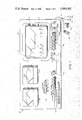
- FIG. 1 shows an automotive ignition analyzer with cylinder of interest display according to the instant invention
- FIG. 2 shows in schematic form the horizontal circuitry of the analyzer of FIG. 1;
- FIG. 3 shows the vertical circuitry of the analyzer of FIG. 1
- FIG. 4 is a series of graphical representations of signals developed in the circuitry of FIGS. 2 and 3.
- FIG. 1 shows automotive engine analyzer 100 according to the instant invention.
- cathode ray oscilloscopic display 104 upon which the traces described below herein are displayed.
- "Number of cylinders" select switch 30 includes pushbutton 106 for rotary engines, pushbutton 108 for four cylinder engines, pushbutton 110 for six cylinder engines, and pushbutton 112 for eight cylinder engines. The purpose of this switch will be described below in greater detail with respect to FIG. 2.
- Analyzer 100 also includes "cylinder of interest" select switch 40 having pushbuttons 41 through 48 representing the selection of cylinders 1 through 8 respectively.
- power balance pushbutton 64 Also included on panel 102 is power balance pushbutton 64, vertical spread adjustment 114 and vertical position adjustment 116.
- Display mode select switch 118 includes pushbuttons 120 and 122 for primary display of 40 volts and 400 volts, respectively, and pushbuttons 124 and 126 for secondary display of 20,000 and 40,000 volts, respectively. Additionally, pushbutton 128 selects the parade mode of display and pushbutton 130 selects the stacked mode display. Horizontal adjustments are provided by horizontal position adjustment 132 and gain adjustment 134. Also included on panel 102 is indicator 136 which may conveniently be a tachometer and indicator 138 which may be a voltmeter.
- Analyzer 100 is operated from a conventional source of power and is connected to the internal combustion engine to be analyzed by cable 140 which includes primary clip lead 142, secondary capacitive coupler 144, cylinder No. 1 probe 148 and ground lead 146.
- analyzer 100 may be operated as follows.
- the proper pushbutton within switch 30 must be actuated for the number of cylinders of the engine to be tested.
- Switch 118 must be actuated to choose between parade or stacked modes of display and between primary or secondary signal pickups, together with the voltage range therefor. If stacked pushbutton 130 is actuated, oscilloscope 104 will display the number of traces represented by the pushbutton of switch 30 actuated. That is, for an eight cylinder engine, eight separate traces will be displayed, one for each cylinder.
- the vertical distance between each trace may be modified by adjustment of spread adjust 114 and the traces may be rolled or moved in a vertical direction by adjustment of vertical position adjust 116.
- Horizontal position adjust 132 serves to move the traces in the horizontal direction for convenience or to line up the traces with convenient scale markings.
- Gain adjustment 134 may be utilized to expand the horizontal scale in order to investigate in more detail a portion of the traces.
- parade pushbutton 128 If parade pushbutton 128 is actuated, a single trace will appear across the screen displaying, in sequence, signals representing the firing of all of the cylinders in the engine.
- actuation of one of the pushbuttons in cylinder of interest select switch 40 causes the display representing the appropriately numbered cylinder to be removed from the parade display and positioned in the stacked mode.
- the parade display as shown in trace A will include cylinders 1 through 8 of an eight cylinder engine except cylinder 5 which will be positioned vertically thereabove as shown in trace B in an expanded horizontal scale.
- power balance switch 64 is depressed, cylinder No. 5 will not be allowed to fire. It is possible by first actuating and then releasing pushbutton 64 to determine the difference in engine speed as indicated on tachometer 136 resulting from the operation of cylinder 5. This is the power balance test and can be used as an indication of the relative effectiveness and/or power contribution of each cylinder.
- FIG. 2 shows in schematic form horizontal circuitry 10 of analyzer 100 which develops the horizontal input for oscilloscopic display 104 according to the instant invention.
- Pulse shaping network 12 which may be any suitable filtering or shaping circuit, is tied to the primary of the ignition system, i.e. the ungrounded side of the points, by probe 142.
- the signal provided by pulse shaping circuit 12 is used to trigger one shot 14 which provides the signal OS1.
- This pulse occurs coincident with the leading edge or some other predetermined part of the firing of every cylinder.
- OS1 is utilized to trigger ramp generator 16 the output of which is designated herein as the cylinder firing ramp, CFR.
- This ramp drives the horizontal input circuitry 54 of oscilloscope 104 when switch 52 is closed so as to move the trace through its horizontal range of motion during the time between successive OS1 pulses.
- Pulse shaping network 18 is connected to cylinder No. 1 by probe 148. This may be the same cylinder No. 1 as designated by the manufacturer of the engine for convenience but need not be so. Pulse shaping circuit 18 provides the same function as circuit 12 and serves to trigger one shot 20 which provides the pulse OS2. This pulse occurs once per engine cycle, that is, coincident with the leading edge or some other part of the firing of cylinder No. 1. OS2 is utilized to trigger ramp generator 22 the output of which is designated herein as the engine cycle ramp, ECR. This ramp is applied to the horizontal input circuitry 54 of oscilloscope 104 when switch 58 is closed in order to move the trace through its horizontal range of motion once per engine cycle, that is, for every cycle of firing of all cylinders in the engine.
- Counter 24 is provided with OS1 at its count input and generates the signals CL1-CL8.
- CL1 is the output time of counter 24 representing the initiation of firing of cylinder No. 1, etc.
- Counter 24 is reset by OS2 which is connected through OR gate 26 to the reset input of counter 24.
- the other input to OR gate 26 is the output of AND gate 28 which combines OS1 with the clear set signal CLRSET.
- CLRSET is generated by number of cylinders switch 30 which is utilized to program analyzer 100 for the number of cylinders in the particular internal combustion engine to be tested.
- Pushbuttons 106, 108, 110 and 112 within pushbutton 30 select signals CL2, CL4, CL6 and CL8 respectively as CLRSET for 2, 4, 6 and 8 cylinder engines.
- Rotary engines are equivalent to 2 cylinder engines for this purpose.
- CLRSET when synchronized by OS1 in AND gate 28, resets counter 24 through OR gate 26 so that counter 24 may also be reset by OS2 which represents the firing of cylinder No. 1.
- OR gate 32 is utilized to generate the signal SELPULS.
- the signal CL4 could be utilized, for example, as the cylinder of interest pulse, COI, for selecting cylinder 4.
- COI the cylinder of interest pulse
- SELPULS is generated by the output of counter 24 corresponding to the cylinder firing just before the firing of the cylinder of interest selected.
- Each pushbutton has two positions, the OFF position in this embodiment representing a ground connection.
- the actuated pushbutton connects the appropriate output of counter 24 to the appropriate input of OR gate 32.
- pushbutton 48 corresponding to cylinder No. 8 is connected between CL7 and OR gate 32.
- pushbutton 47 representing cylinder No. 7 is connected between CL6 and OR gate 32, etc.
- Pushbutton 41 representing cylinder No. 1, is connected between the output of switch 30, which is CLRSET, and OR gate 32. In this manner it can be seen that SELPULS is generated by the firing of the cylinder immediately preceding the selected cylinder of interest.
- SELPULS is provided at the clocked SET input of clocked flip-flop 50, the set output of which is the cylinder of interest pulse COI.
- the clock input to flip-flop 50 is provided by OS1.
- flip-flop 50 is set by SELPULS so that COI is generated at the same instant as OS1 for the selected cylinder.
- COI is utilized in both the horizontal and vertical circuitry.
- COI operates switch 78 in a manner described below with reference to FIG. 3.
- COI is utilized to activate switch 52 which applies CFR generator 16 to the input of horizontal amplifying circuitry 54.
- Horizontal amplifying circuitry 54 includes preamp 88 in the feedback path of which is variable resistance 90 which serves as horizontal position adjustment 132 shown in FIG. 1.
- the input for preamp 88 is provided by the outputs of switches 52 and 58 as discussed above.
- the output of preamp 88 is connected through variable resistance 92, which serves as gain adjustment 134, to horizontal amplifier 94 the output of which provides the horizontal input for oscilloscope 104.
- SELPULS is also inverted by inverter 68 and connected to the clocked RESET input of flip-flop 50, the RESET output of which is utilized to operate switch 58.
- ECR generator 22 If a cylinder of interest is selected the horizontal input to oscilloscope 104, during the firing time of that cylinder of interest, the input to horizontal amplifying circuitry 54 is provided by CFR generator 16. During the remainder of the engine cycle, the horizontal input to the oscilloscope display is provided by ECR generator 22.
- SELPULS is connected to the clocked SET input of clock flip-flop 60, the clock input of which is also provided by OS1.
- SELPULS after inversion by inverter 68, is connected to the clocked RESET input of flip-flop 60.
- the SET output of flip-flop 60 is COI' and is connected through OR gate 62 to power balance switch 64. If power balance switch 64 is activated, then COI' is provided to the power balance ignition prevention circuit, generally shown as shorting circuit 66. This may conveniently be a high power transistor switch connected across the points of the ignition to prevent firing of a cylinder when activated. As can be seen from the above description, when power balance switch 64 is activated any cylinder of interest selected will be prevented from firing.
- pushbuttons 41-48 With a second gang of switches 49 all of which are arranged so that if any one of the above-mentioned pushbuttons is activated, the signal V-OFF is generated from a d.c. source not shown. V-OFF is inverted by inverter 69 and connected to the input of OR gate 62. In this manner it can be seen that if power balance switch 64 is activated and none of the cylinder of interest select pushbuttons 41-48 are activated, shorting circuit 66 will continuously prevent the firing of any cylinder. Thus, power balance switch 64 doubles as a so-called "kill button" to turn the engine off.
- Switch 70 serves as pushbuttons 128 and 130 shown in FIG. 1 to select between the parade and stacked modes.
- Switch 70 is provided as a direct set for flip-flop 50. Activation of switch 70 sets flip-flop 50 which activates switch 52 to connect CFR ramp generator 16 to the horizontal input of oscilloscope 104. Therefore, when switch 70 is activated, flip-flop 50 is locked in the set mode, COI is continuously present and analyzer 100 is in the stacked mode of operation as will be explained in greater detail below. When switch 70 is not activated, analyzer 100 is in the parade mode since switch 58 is activated by the reset side of flip-flop 50.
- Counter 72 and resistors R, 2R and 4R provide both a counting and digital-to-analog converting function so that a first analog value is provided during the firing of cylinder No. 1 and a second analog value, twice the first, is provided during the firing of cylinder No. 2 and so on.
- These analog values are provided to vertical input amplifier 74 through spread amplifier 76 and switch 78.
- Variable resistance 77 in the feedback loop of amplifier 76 serves as vertical spread adjustment 114.
- switch 78 is activated by COI (which in the stacked mode is continuously present), a vertical offset is provided for each cylinder firing so that in the stacked mode the traces representing the various cylinders are separated vertically for ease of interpretation. The vertical separation therebetween is controlled by adjustment 114.
- panel 102 contains switches 120, 122, 124 and 126 which allow the mechanic to choose two ranges in either primary or secondary display.
- the primary display signal developed by probe 142 is connected by switch 120 or 122 to resistors 121 and 123, respectively, which are connected at the input of primary amplifier 80.
- the signal developed by secondary capacitive coupler 144 is applied to the input of secondary amplifier 82 and connected to the input of amplifier 80 by either pushbutton 124 or 126 through resistors 125 or 127, respectively.
- the resistor values controls the range or gain of the amplifying stages in a conventional manner.
- variable resistor 86 provides the vertical adjustment 116 mentioned in connection with FIG. 1.
- FIG. 4 is a series of graphs, on the same time scale, of the signals present in the circuitry shown in FIGS. 2 and 3.
- FIG. 4A represents the signals at the input to pulse shaping circuit 12 developed by probe 142. These signals represent the voltage developed across the primary of the ignition coil and distributed by the engine's distributor, not shown, to the individual cylinders. For convenience the pulses representing the firing of the individual cylinders are labeled 1-8 corresponding to the cylinder markings.
- Graph 4B shows OS1 generated by one shot 14 coincident with the leading edge of the firing of every cylinder.
- Graph 4C shows the output of CFR generator 16, the beginning of which is coincident with the leading edge of OS1.
- Graph 4D shows OS2 generated by one shot 20 in response to the firing of cylinder No. 1 as detected by probe 148 and pulse shaping circuit 18. OS2 is therefore generated only once per cycle of cylinder firings.
- Graph 4E shows the output of ECR generator 22 in response to OS2.
- this ramp is applied to the horizontal input of oscilloscope 104, the trace is moved across the screen once per engine cycle so that the display on the screen would be the same as the graph of FIG. 4A for cylinders 1- 8. This is the parade mode.
- Graph 4F represents the output states of counter 24. As seen, CL1 is present during the firing of cylinder 1, CL2 is present during the firing of cylinder 2, etc.
- Graph 4G represents the output of counter 72 showing the staircase effect, that is, the output increases one step from cylinders 1 through 8 and is then reset to start again. This results in the vertical deflection required for the stacked mode of operation.
- Graph 4H represents the signal SELPULS at the output of OR gate 32 in FIG. 1 when cylinder No. 5 is selected as the cylinder of interest by actuation of pushbutton 45. It is important to note at this point that SELPULS for cylinder of interest No. 5 is effectively the CL4 output of counter 24 representing the firing of cylinder No. 4.
- Graph 4I represents COI for cylinder No. 5 which occurs during the firing of cylinder No. 5.
- Graph 4J represents the horizontal input to the oscilloscopic display when cylinder No. 5 is selected as the cylinder of interest. From time TO to T5 ECR is applied to the horizontal input as it is from time T6 to T0. However, during the firing time of cylinder No. 5, selected as the cylinder of interest, CFR is applied. During this complete engine cycle the vertical input to oscilloscopic display 104 is selected by pushbuttons 120, 122, 124 or 126. To this is added the additional vertical displacement caused by signal COI as discussed previously only during the firing of cylinder No. 5. The resultant display is shown in FIG. 1 as traces A and B.
- Trace A displays the firing of all cylinders except the cylinder of interest selected, i.e. except cylinder No. 5. Cylinder No. 5 is displayed in trace B in the stacked mode vertically separated from trace A.
Landscapes
- Engineering & Computer Science (AREA)
- Chemical & Material Sciences (AREA)
- Combustion & Propulsion (AREA)
- Physics & Mathematics (AREA)
- General Physics & Mathematics (AREA)
- Mechanical Engineering (AREA)
- General Engineering & Computer Science (AREA)
- Ignition Installations For Internal Combustion Engines (AREA)
- Testing Of Engines (AREA)
Priority Applications (6)
| Application Number | Priority Date | Filing Date | Title |
|---|---|---|---|
| US05/635,738 US3990302A (en) | 1975-11-26 | 1975-11-26 | Automotive ignition analyzer with cylinder of interest display |
| CA265,804A CA1050110A (en) | 1975-11-26 | 1976-11-16 | Automotive ignition analyzer with cylinder of interest display |
| DE2653640A DE2653640C2 (de) | 1975-11-26 | 1976-11-25 | Zündanalysegerät für Mehrzylinder- Verbrennungsmotoren |
| GB49123/76A GB1561760A (en) | 1975-11-26 | 1976-11-25 | Automotive ignition analyzer with cylinder of interest display |
| FR7635538A FR2333132A1 (fr) | 1975-11-26 | 1976-11-25 | Analyseur d'allumage automobile avec visualisation du cylindre interesse |
| JP1976157548U JPS585102Y2 (ja) | 1975-11-26 | 1976-11-26 | 目標シリンダのデイスプレイを有する自動車点火分析装置 |
Applications Claiming Priority (1)
| Application Number | Priority Date | Filing Date | Title |
|---|---|---|---|
| US05/635,738 US3990302A (en) | 1975-11-26 | 1975-11-26 | Automotive ignition analyzer with cylinder of interest display |
Publications (1)
| Publication Number | Publication Date |
|---|---|
| US3990302A true US3990302A (en) | 1976-11-09 |
Family
ID=24548915
Family Applications (1)
| Application Number | Title | Priority Date | Filing Date |
|---|---|---|---|
| US05/635,738 Expired - Lifetime US3990302A (en) | 1975-11-26 | 1975-11-26 | Automotive ignition analyzer with cylinder of interest display |
Country Status (6)
| Country | Link |
|---|---|
| US (1) | US3990302A (show.php) |
| JP (1) | JPS585102Y2 (show.php) |
| CA (1) | CA1050110A (show.php) |
| DE (1) | DE2653640C2 (show.php) |
| FR (1) | FR2333132A1 (show.php) |
| GB (1) | GB1561760A (show.php) |
Cited By (12)
| Publication number | Priority date | Publication date | Assignee | Title |
|---|---|---|---|---|
| US4145746A (en) * | 1977-01-03 | 1979-03-20 | Sun Electric Corporation | Engine tester display and printing techniques |
| USD258805S (en) | 1977-10-13 | 1981-04-07 | Rite Autotronics Corporation | Digital engine analyzer |
| US4788505A (en) * | 1987-09-11 | 1988-11-29 | Pacific Northwest Electronics | Advance reference cylinder trigger generator |
| USD299910S (en) | 1986-06-23 | 1989-02-21 | Snap-On Tools Corporation | Engine analyzer |
| US4847563A (en) * | 1988-07-12 | 1989-07-11 | Snap-On Tools Corporation | Distributorless ignition interface |
| US4937527A (en) * | 1988-07-12 | 1990-06-26 | Snap-On Tools Corporation | Lead assembly for a distributorless ignition interface |
| US5182512A (en) * | 1990-10-29 | 1993-01-26 | Snap-On Tools Corporation | Method and apparatus for determining relative contributions of individual cylinders of internal combustion engine using contact tachometer |
| US5680311A (en) * | 1995-12-29 | 1997-10-21 | Snap-On Tools Company | Long term firing and spark display |
| US5719765A (en) * | 1995-08-07 | 1998-02-17 | Snap-On Technologies, Inc. | Real-time scrolling drive-trace display for a vehicle engine analyzer |
| US6237400B1 (en) * | 1997-02-03 | 2001-05-29 | Honda Giken Kogyo Kabushiki Kaisha | Vehicle diagnosing apparatus |
| US20170002785A1 (en) * | 2015-06-30 | 2017-01-05 | Chung-Yi HUANG | Vehicle ignition system detection device |
| CN106499095A (zh) * | 2016-12-23 | 2017-03-15 | 万保金 | 预制模壳内置预应力筋型钢混凝土墙 |
Citations (3)
| Publication number | Priority date | Publication date | Assignee | Title |
|---|---|---|---|---|
| US3548300A (en) * | 1968-09-30 | 1970-12-15 | Texaco Inc | Method and apparatus for an ignition timing indicator |
| US3650149A (en) * | 1969-01-21 | 1972-03-21 | Clayton Manufacturing Co | Engine ignition and power analyzer |
| US3798965A (en) * | 1970-05-13 | 1974-03-26 | Autoscan Inc | System for testing the ignition of an internal combustion engine |
Family Cites Families (2)
| Publication number | Priority date | Publication date | Assignee | Title |
|---|---|---|---|---|
| US2962625A (en) * | 1958-10-06 | 1960-11-29 | Dresser Ind | Oscillograph deflection circuit |
| JPS4925970A (show.php) * | 1972-06-29 | 1974-03-07 |
-
1975
- 1975-11-26 US US05/635,738 patent/US3990302A/en not_active Expired - Lifetime
-
1976
- 1976-11-16 CA CA265,804A patent/CA1050110A/en not_active Expired
- 1976-11-25 FR FR7635538A patent/FR2333132A1/fr active Granted
- 1976-11-25 GB GB49123/76A patent/GB1561760A/en not_active Expired
- 1976-11-25 DE DE2653640A patent/DE2653640C2/de not_active Expired
- 1976-11-26 JP JP1976157548U patent/JPS585102Y2/ja not_active Expired
Patent Citations (3)
| Publication number | Priority date | Publication date | Assignee | Title |
|---|---|---|---|---|
| US3548300A (en) * | 1968-09-30 | 1970-12-15 | Texaco Inc | Method and apparatus for an ignition timing indicator |
| US3650149A (en) * | 1969-01-21 | 1972-03-21 | Clayton Manufacturing Co | Engine ignition and power analyzer |
| US3798965A (en) * | 1970-05-13 | 1974-03-26 | Autoscan Inc | System for testing the ignition of an internal combustion engine |
Cited By (12)
| Publication number | Priority date | Publication date | Assignee | Title |
|---|---|---|---|---|
| US4145746A (en) * | 1977-01-03 | 1979-03-20 | Sun Electric Corporation | Engine tester display and printing techniques |
| USD258805S (en) | 1977-10-13 | 1981-04-07 | Rite Autotronics Corporation | Digital engine analyzer |
| USD299910S (en) | 1986-06-23 | 1989-02-21 | Snap-On Tools Corporation | Engine analyzer |
| US4788505A (en) * | 1987-09-11 | 1988-11-29 | Pacific Northwest Electronics | Advance reference cylinder trigger generator |
| US4847563A (en) * | 1988-07-12 | 1989-07-11 | Snap-On Tools Corporation | Distributorless ignition interface |
| US4937527A (en) * | 1988-07-12 | 1990-06-26 | Snap-On Tools Corporation | Lead assembly for a distributorless ignition interface |
| US5182512A (en) * | 1990-10-29 | 1993-01-26 | Snap-On Tools Corporation | Method and apparatus for determining relative contributions of individual cylinders of internal combustion engine using contact tachometer |
| US5719765A (en) * | 1995-08-07 | 1998-02-17 | Snap-On Technologies, Inc. | Real-time scrolling drive-trace display for a vehicle engine analyzer |
| US5680311A (en) * | 1995-12-29 | 1997-10-21 | Snap-On Tools Company | Long term firing and spark display |
| US6237400B1 (en) * | 1997-02-03 | 2001-05-29 | Honda Giken Kogyo Kabushiki Kaisha | Vehicle diagnosing apparatus |
| US20170002785A1 (en) * | 2015-06-30 | 2017-01-05 | Chung-Yi HUANG | Vehicle ignition system detection device |
| CN106499095A (zh) * | 2016-12-23 | 2017-03-15 | 万保金 | 预制模壳内置预应力筋型钢混凝土墙 |
Also Published As
| Publication number | Publication date |
|---|---|
| FR2333132A1 (fr) | 1977-06-24 |
| JPS585102Y2 (ja) | 1983-01-28 |
| CA1050110A (en) | 1979-03-06 |
| DE2653640C2 (de) | 1985-09-26 |
| FR2333132B1 (show.php) | 1982-11-12 |
| JPS5277338U (show.php) | 1977-06-09 |
| GB1561760A (en) | 1980-02-27 |
| DE2653640A1 (de) | 1977-06-08 |
Similar Documents
| Publication | Publication Date | Title |
|---|---|---|
| US3990302A (en) | Automotive ignition analyzer with cylinder of interest display | |
| US3789658A (en) | Engine performance analyzer | |
| USRE29984E (en) | Engine ignition and power analyzer | |
| US5396427A (en) | Method and apparatus for determining relative contributions of individual cylinders of internal combustion engine | |
| DE3689281D1 (de) | Digitaler Analysator für einen Motor. | |
| US3573608A (en) | Engine analyzing apparatus with cathode ray display | |
| US4373394A (en) | Ultrasonic test apparatus and sweep voltage generator for use therein | |
| US2607215A (en) | Multiple mixing circuit for electronic detonation pickups | |
| US5068613A (en) | Method and apparatus for generating display waveforms im wasted spark ignition systems | |
| US3035438A (en) | Test apparatus for internal combustion engines | |
| US2787760A (en) | Automotive engine analyzer | |
| US2740069A (en) | Engine analyzer | |
| US3449671A (en) | Oscillographic apparatus for measuring the magnitude and duration of input waveforms | |
| USRE31656E (en) | Engine ignition and power analyzer | |
| US5778328A (en) | Engine analyzer with single-head ignition scope | |
| US3798965A (en) | System for testing the ignition of an internal combustion engine | |
| US4686523A (en) | Cursor display for oscilloscopes | |
| US2458771A (en) | Supersonic reflectoscope | |
| US4010419A (en) | Ignition analyzer time base | |
| US4170131A (en) | Single sensor engine analyzer with noise rejection and automatic triggering circuit | |
| US3665294A (en) | System for determining the ignition advance in the distribution of an engine | |
| US3243997A (en) | Analyzer for internal combustion engines | |
| US4333345A (en) | Display of ultrasound test data | |
| US3354392A (en) | Cathode ray voltmeter using sweep signal for scale generation and for input signal level comparison | |
| US4064450A (en) | Engine scope tester calibrator |
Legal Events
| Date | Code | Title | Description |
|---|---|---|---|
| AS | Assignment |
Owner name: BECKMAN INDUSTRIAL CORPORATION A CORP OF DE Free format text: ASSIGNMENT OF ASSIGNORS INTEREST.;ASSIGNOR:EMERSON ELECTRIC CO., A CORP OF MO;REEL/FRAME:004328/0659 Effective date: 19840425 Owner name: EMERSON ELECTRIC CO., A MO CORP. Free format text: ASSIGNMENT OF ASSIGNORS INTEREST.;ASSIGNOR:BECKMAN INSTRUMENTS, INC.;REEL/FRAME:004319/0695 Effective date: 19840301 |
|
| AS | Assignment |
Owner name: ROSEMOUNT INC., MINNESOTA Free format text: ASSIGNMENT OF ASSIGNORS INTEREST.;ASSIGNOR:BECKMAN INDUSTRIAL CORPORATION;REEL/FRAME:005243/0057 Effective date: 19890523 |