US3955496A - Linear can printer - Google Patents
Linear can printer Download PDFInfo
- Publication number
- US3955496A US3955496A US05/506,907 US50690774A US3955496A US 3955496 A US3955496 A US 3955496A US 50690774 A US50690774 A US 50690774A US 3955496 A US3955496 A US 3955496A
- Authority
- US
- United States
- Prior art keywords
- conveyor
- printing
- mandrel
- apparatus recited
- sprocket
- Prior art date
- Legal status (The legal status is an assumption and is not a legal conclusion. Google has not performed a legal analysis and makes no representation as to the accuracy of the status listed.)
- Expired - Lifetime
Links
- 238000007639 printing Methods 0.000 claims abstract description 60
- 230000007246 mechanism Effects 0.000 claims description 14
- 230000005540 biological transmission Effects 0.000 claims 1
- 238000001514 detection method Methods 0.000 claims 1
- 238000001035 drying Methods 0.000 description 8
- 239000003086 colorant Substances 0.000 description 4
- 238000009987 spinning Methods 0.000 description 3
- 230000001419 dependent effect Effects 0.000 description 1
- 238000006073 displacement reaction Methods 0.000 description 1
- 230000005484 gravity Effects 0.000 description 1
- 238000003780 insertion Methods 0.000 description 1
- 230000037431 insertion Effects 0.000 description 1
- 230000013011 mating Effects 0.000 description 1
- 238000012986 modification Methods 0.000 description 1
- 230000004048 modification Effects 0.000 description 1
- 239000003973 paint Substances 0.000 description 1
- 230000000750 progressive effect Effects 0.000 description 1
- 238000004904 shortening Methods 0.000 description 1
Images


Classifications
-
- B—PERFORMING OPERATIONS; TRANSPORTING
- B41—PRINTING; LINING MACHINES; TYPEWRITERS; STAMPS
- B41F—PRINTING MACHINES OR PRESSES
- B41F17/00—Printing apparatus or machines of special types or for particular purposes, not otherwise provided for
- B41F17/08—Printing apparatus or machines of special types or for particular purposes, not otherwise provided for for printing on filamentary or elongated articles, or on articles with cylindrical surfaces
- B41F17/14—Printing apparatus or machines of special types or for particular purposes, not otherwise provided for for printing on filamentary or elongated articles, or on articles with cylindrical surfaces on articles of finite length
- B41F17/20—Printing apparatus or machines of special types or for particular purposes, not otherwise provided for for printing on filamentary or elongated articles, or on articles with cylindrical surfaces on articles of finite length on articles of uniform cross-section, e.g. pencils, rulers, resistors
- B41F17/22—Printing apparatus or machines of special types or for particular purposes, not otherwise provided for for printing on filamentary or elongated articles, or on articles with cylindrical surfaces on articles of finite length on articles of uniform cross-section, e.g. pencils, rulers, resistors by rolling contact
Definitions
- This invention relates to apparatus for printing patterns on cans and similar cylindrical objects and more particularly to a can printer having a linear conveyor with the printing stations spaced longitudinally along the linear conveyor.
- a typical rotary printer has a plurality of mandrels on a mandrel drum. The mandrels carry the cans into contact with a rotating printing blanket. Examples of such rotary can printers are shown in U.S. Pat. Nos. 3,587,816 - Russell et al and 3,496,863 - Cvacho et al.
- a printer for cans and similar cylindrical objects includes a linear conveyor which moves these objects between a feed station and a discharge station.
- a plurality of printing mechanisms are spaced longitudinally along the linear conveyor to provide room for each different color pattern to dry before the printing of the next pattern and to provide easy access to each of the printing stations.
- a compensated conveyor provides a constant velocity of the cans past the printing mechanisms.
- can carrying mandrels on the conveyor are continuously rotated in synchronism with the rotation of the printing cylinders so that correct registration of a printing pattern on the cans is achieved without slippage between the can and the printing cylinder which might otherwise cause smudging of the pattern.
- the continuous rotation of the mandrels between printing stations aids the drying of the printed patterns.
- a novel and useful compensating link is provided in the linear conveyor.
- each of the mandrels is expandible into gripping relationship with the cans.
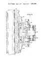
- FIG. 1 is a partially diagrammatic top plan view of a machine embodying the principles of this invention
- FIG. 2 is an end view of the machine shown in FIG. 1;
- FIGS. 3A, 3B combined form a front elevation of the machine shown in FIG. 1;
- FIG. 4 is a front elevation view of a typical printing mechanism for the disclosed device
- FIG. 5 is a trimetric drawing illustrating a section of the conveying chain with a mandrel assembly affixed thereto;
- FIG. 6 is a view similar to FIG. 5 but showing only the chain components
- FIG. 7 is a trimetric view of the male link of the disclosed chain
- FIG. 8 is a trimetric drawing of the female link
- FIG. 9 is a fragmentary, partially sectioned view of the mandrel assembly showing its connection to the conveyor chain;
- FIG. 10 is an elevation view of a typical mandrel assembly with parts broken away to disclose a detent mechanism
- FIG. 11 is a view similar to FIG. 10 but showing the bearing means for the constant velocity chain
- FIG. 12 is a cross sectional view through an expandible mandrel
- FIG. 13 is a view taken along the lines 13--13 of FIG. 12;
- FIG. 14 is a view taken along the lines 14-- 14 of FIG. 12;
- FIG. 15 is a top plan view of the constant velocity chain and its associated structure
- FIG. 16 is a view taken along the lines 16--16 of FIG. 15;
- FIGS. 17 and 18 are orthographic views illustrating the "no can - no print" mechanism.
- the disclosed printing machine 1 comprises a base 2, a frame 4, a can feeding station 6, a plurality of printers 8, a plurality of drying ovens 10, a constant velocity linear conveyor 12 and a can discharge station 14.
- Cans 3 to be printed are fed to the machine via a gravity fed chute 16 where they are then introduced to a separting and spacing screw 18 after which they are picked up by a can insertion conveyor 20 (FIG. 3).
- Conveyor 20, coupled with a cam track 22, then progressively inserts the cans 3 onto each successive mandrel 24 as they pass in timed sequence.
- each mandrel 24, with a can 3 is presented to one or more printing and drying stations until the finished can is finally ejected at discharge station 14.
- a drying oven 10 containing ultraviolet lights or other drying means conditions the can for the next printing station.
- the disclosed machine contains five printing and five drying stations, but any reasonable number of stations may be used simply by lengthening or shortening the frame and conveyor mechanism.
- the printers 8 have wheels 28 which are set on tracks 26 for movement on the base 2. This provides easy engagement and disengagement of the printers with the conveyors. This enables the machine to be preset for a variety of labels to be printed.
- the first two printers may be set up for a label containing two colors and the latter three printers for a label containing three colors.
- the last three printers would be moved away from the conveyor 12 via tracks 26 and wheels 28 whereby they would not be in a printing position. Only the first two printers would be used and the finished cans would be ejected at station 14.
- the first two printers When it is desired to print the three color label, the first two printers would be disengaged from the conveyor and the last three would be engaged with the conveyor, thereby giving the machine useful flexibility.
- each printer 8 is of the standard off-set type wherein the ink is supplied from ink fountain 30, and is transmitted through a series of rollers 32 to a plate roller 34 and then to a printing cylinder. It will be recognized that a gravure printer or a combination of known printers could be used.
- the printer which is shown comprises a printing blanket 36 on a drum 38 fixed for rotation on a shaft 40. Shaft 40 is driven by a timing belt 42 connected to a sprocket fixed on the splined shaft 44 of a rectangular drive 46.
- Each printing mechanism and the loading and unloading conveyors are driven off individual rectangular drives 46, all commonly joined to a first rectangular drive 47 (FIG. 3B) which is driven by a motor 48 through a timing belt 50. Rectangular drive 47, through a right angle drive, also drives a vertical shaft 52 which as viewed in FIG. 15 causes the rotational movement of conveyor 12.
- each successive printing station As the cans are presented to each successive printing station, they must be in perfect registration or the succeeding print will over-print, overlap or otherwise misprint and the label will be ruined.
- Each can must meet the successive printers at a precise point so the different colors of print will be placed in their proper relative positions to create the desired label. This demanded feature precludes permitting the cans to "free wheel" as they are met by the printer.
- each can must be firmly gripped by its mandrel and all movement of the mandrel must be totally controlled.
- the mandrel must rotate as it passes over the printer and the rotational speed must equal that of the printing cylinder.
- the rotation and control of the mandrel is provided by a mandrel control unit 54 fixed to the chain and shown in trimetric in FIG. 5 and in cross-section in FIG. 9.
- the unit comprises a frame 56, a jack shaft 58, a gear train, a mandrel 24 and a control roller 60.
- the gear train comprises gears 68 and 70 on shaft 58 and gear 72 which meshes with gear 70.
- Shaft 58 is fixed at 62 to the conveyor 12.
- a spherical adjustment is provided in that joint to set the mandrel 24 in parallel relationship with the printing blanket 36.
- a main support plate 64 fixed to frame 4 supports a track 144 for the chain rollers and a linear gear rack 66 to impart rotational movement to a small gear 68 fixed for rotation on shaft 58.
- Integral with gear 68 is a large gear 70 which mates with a small gear 72 fixed to the mandrel shaft.
- Gear 68 is driven at the same speed as the linear movement of the conveyor and the mandrel. Through the disclosed gear train, it is driven at a speed equal to that of the printing cylinder. In the event it is desired to mechanically connect the mandrel to the printing roller, the mass 74 on the mandrel may be machined with teeth to mesh with a mating gear on the printing roller.
- the space between the printing stations is calculated on the basis of rack gear teeth so that, although the mandrels are spinning, it is a controlled spin and the mandrels will introduce the proper point on the can to the proper points on the printers as the can advances to each succeeding station.
- a detent mechanism 76 (FIG. 10) which is pivotally mounted in the frame 56 and which snaps in and out of a recess 78 in the collar of gear 68, 70. Recess 78 represents ZERO tooth position when detent 76 is engaged.
- each can 3 must be firmly gripped by its particular mandrel 24. This is accomplished by means of an expanding type mandrel. Any type would suffice, but for the purposes of disclosure, a particular embodiment is shown in FIGS. 12, 13 and 14.
- This mandrel comprises a two piece outer section 80, 82 joined together by an inner member 84, a pair of slides 86 and an actuating shaft 88.
- Slides 86 contain hardened balls 90 which cooperate with cam surfaces 92 and 94 on shaft 88 to either force the slides down in FIG. 12, to allow a can to be inserted or ejected, or to force the slides up through the bias of springs 96, to expand the mandrel for firm gripping of can 3.
- An external operating lever 98 is provided.
- the mandrel shaft 102 is provided with an axial air hole 104 which then communicates with a pair of air holes 106 on the can side of the mandrel and an air blast supply on the other side.
- This air blast is utilized to eject the finished can on suction cups or magnetic pads at station 14 and also to eject any can that has not been properly placed on the mandrel before subsequent printing.
- a sensing mechanism signals the air blast if the can is not on all the way and the can is blasted off the mandrel.
- a mechanism is provided at each printing station whereby a sensor 108 detects the presence of no can and triggers an air cylinder 110 to remove the mandrel from any contact with the printing blanket, thereby avoiding getting paint or ink on the mandrel itself. This is shown in FIGS. 17 and 18.
- the previously described mandrel control unit 54 is biased in a clockwise direction about shaft 58 by a torsion spring 112, one end of which is fixed to the stationary shaft 58 and the other end to a pin 114 on the frame 56.
- the mandrel is biased toward the print roller 38 by means of a cam surface 116 acting on the control roller 60.
- This cam surface is part of a bell crank 118 pivotally connected to the machine frame at 120 and to the piston rod of air cylinder 110 at 122.
- the sensor 108 detects no can, it triggers cylinder 110 to rotate bell crank 118 to the position of FIG. 18, thereby allowing unit 54 to pivot clockwise under the influence of spring 112. As shown in FIG. 18, this motion removes the mandrel from contact with the printing wheel and the mandrel stays clean.
- a similar mechanism is provided at each printing station.
- a constant velocity chain which contains no slack and which moves uniformly with total accuracy.
- Each section of this chain is made up of a male link 124 (FIG. 7), a female link 126 (FIG. 8) and a plurality of ball bearing rollers.
- Each link has rounded portions 12a, 12b, on the male link and 126a, 126b on the female link.
- Both links 124, 126 are provided with a mounting hole 128 to receive a shaft 58 on each mandrel unit 54 (FIG. 9).
- the interconnection of the associated chain components is shown in FIG. 6.
- a pin 130 extends through holes in the rounded portions of each link and through matching holes in compensating rollers 132.
- a pin 134 extends through holes in the rounded portions of male link 124 and through matching holes in a second pair of compensating rollers 136.
- a pair of vertically disposed guide rollers 138 is also fixed to each link, male and female.
- rollers 138 can be seen in FIG. 11 where they are shown riding on an upper bearing plate 140 and a lower bearing plate 142 to stabilize the chain as it moves along its straight path.
- compensating rollers 132 can be seen bearing against a cam track 144.
- the compensating rollers 132 leave the cam track 144 which also comes to an end as seen in FIG. 15.
- Merging with that cam track in a spaced apart relationship is a pair of calculated compensating curved tracks 148 which cooperate with rollers 136 to eliminate all slack as the chain travels its circular path around the sprocket.
- This compensating factor provides for a slackless chain and thereby a constant velocity chain which travels with the necessary accuracy to permit precise registration of mandrel to printer.
- the cans 3 are fed onto the mandrels 24, are constantly rotated at equal speed and in constant time with a plurality of printers 8, are dried between printings and finally are ejected at station 14 by a first air blast similar to that used to eject a badly positioned can, and then by suction means at successive stages of station 14.
- the ink fountains continue to rotate slowly to prevent drying of the ink.
- the mandrels automatically are moved to the no-print condition.
- An advantage of this type of printer is that it can easily be modified to print two cans at a time, thereby greatly increasing capacity. Also, while a horizontal arrangement has been shown, it is possible to orient the conveyor chain at a 90° angle from that shown, thereby providing a vertical arrangement.
Landscapes
- Printing Methods (AREA)
- Specific Conveyance Elements (AREA)
- Attitude Control For Articles On Conveyors (AREA)
- Control Of Conveyors (AREA)
Priority Applications (11)
| Application Number | Priority Date | Filing Date | Title |
|---|---|---|---|
| US05/506,907 US3955496A (en) | 1974-09-17 | 1974-09-17 | Linear can printer |
| ZA00755756A ZA755756B (en) | 1974-09-17 | 1975-09-09 | Linear can printer |
| BE160013A BE833379A (fr) | 1974-09-17 | 1975-09-12 | Dispositif d'impression pour boites de conserve |
| DE19752540794 DE2540794A1 (de) | 1974-09-17 | 1975-09-12 | Vorrichtung zum bedrucken von dosen |
| CA235,452A CA1049323A (en) | 1974-09-17 | 1975-09-15 | Linear can printer |
| SE7510336A SE7510336L (sv) | 1974-09-17 | 1975-09-16 | Anordning for tryckning pa burkar och dylika cylindriska foremal |
| GB38079/75A GB1523446A (en) | 1974-09-17 | 1975-09-16 | Linear can printer |
| ES441005A ES441005A1 (es) | 1974-09-17 | 1975-09-16 | Maquina para imprimir en objetos cilindricos. |
| FR7528314A FR2285244A1 (fr) | 1974-09-17 | 1975-09-16 | Dispositif lineaire d'impression sur objets cylindriques |
| NL7510936A NL7510936A (nl) | 1974-09-17 | 1975-09-17 | Drukinrichting. |
| DK415775A DK415775A (da) | 1974-09-17 | 1975-09-17 | Apparat til trykning pa daser |
Applications Claiming Priority (1)
| Application Number | Priority Date | Filing Date | Title |
|---|---|---|---|
| US05/506,907 US3955496A (en) | 1974-09-17 | 1974-09-17 | Linear can printer |
Publications (1)
| Publication Number | Publication Date |
|---|---|
| US3955496A true US3955496A (en) | 1976-05-11 |
Family
ID=24016420
Family Applications (1)
| Application Number | Title | Priority Date | Filing Date |
|---|---|---|---|
| US05/506,907 Expired - Lifetime US3955496A (en) | 1974-09-17 | 1974-09-17 | Linear can printer |
Country Status (11)
| Country | Link |
|---|---|
| US (1) | US3955496A (da) |
| BE (1) | BE833379A (da) |
| CA (1) | CA1049323A (da) |
| DE (1) | DE2540794A1 (da) |
| DK (1) | DK415775A (da) |
| ES (1) | ES441005A1 (da) |
| FR (1) | FR2285244A1 (da) |
| GB (1) | GB1523446A (da) |
| NL (1) | NL7510936A (da) |
| SE (1) | SE7510336L (da) |
| ZA (1) | ZA755756B (da) |
Cited By (16)
| Publication number | Priority date | Publication date | Assignee | Title |
|---|---|---|---|---|
| US4181228A (en) * | 1977-04-15 | 1980-01-01 | Kuraray Co., Ltd. | Apparatus for conveying cops and bobbins for directly connecting ring frame with winder |
| US4441955A (en) * | 1982-08-05 | 1984-04-10 | Standard Oil Company (Indiana) | Base cup applicator |
| US5183509A (en) * | 1991-04-26 | 1993-02-02 | Gencorp Inc. | Apparatus for application of a material to an internal surface of items of manufacture |
| US5275664A (en) * | 1991-04-26 | 1994-01-04 | Gencorp Inc. | Apparatus for application of a material to an external surface of items of manufacture |
| WO1996032320A1 (en) * | 1995-04-13 | 1996-10-17 | The Mead Corporation | Method and apparatus for loading bottom-loading basket-style carrier |
| US6422379B1 (en) * | 1998-06-01 | 2002-07-23 | Sipa S.P.A. | Apparatus for continuously transferring orderly sequences of preforms of thermoplastic materials |
| US6471038B1 (en) * | 2000-09-01 | 2002-10-29 | Chum Power Machinery Corp. | Container conveying apparatus |
| US6607068B1 (en) * | 1999-04-14 | 2003-08-19 | Ipt Weinfelden Ag | Method and device for conveying unit loads |
| US20040166336A1 (en) * | 1998-12-30 | 2004-08-26 | Glud & Marstrand A/S | Method for replicating a surface relief and an article for holding a surface relief |
| US20050087083A1 (en) * | 2003-06-23 | 2005-04-28 | Francois Dumenil | Machine for printing on articles |
| DE102009014321A1 (de) * | 2009-03-21 | 2010-09-23 | Walz Gmbh & Co. Kg | Verfahren und Vorrichtung zum Bedrucken eines Gegenstands mit gekrümmter Mantelfläche |
| US20110036686A1 (en) * | 2008-04-14 | 2011-02-17 | Yuichi Iwamoto | Conveyer device |
| US20120098914A1 (en) * | 2010-10-25 | 2012-04-26 | Machines Dubuit | Inkjet printing machine |
| ITMI20110537A1 (it) * | 2011-03-31 | 2012-10-01 | Martinenghi S R L | Dispositivo e metodo per la stampa di corpi cilindrici |
| CN104441986A (zh) * | 2014-12-15 | 2015-03-25 | 北京美科艺数码科技发展有限公司 | 喷墨打印装置及喷墨打印方法 |
| WO2018015134A1 (de) * | 2016-07-20 | 2018-01-25 | Koenig & Bauer Ag | Vorrichtung und verfahren zum bedrucken von hohlkörpern mit linear verstellbarer zuführeinrichtung |
Families Citing this family (1)
| Publication number | Priority date | Publication date | Assignee | Title |
|---|---|---|---|---|
| FR2670759B1 (fr) * | 1990-12-19 | 1993-04-09 | Engineering Machine Cy Ltd | Dispositif pour equiper simultanement plusieurs mandrins avec des pieces cylindriques. |
Citations (10)
| Publication number | Priority date | Publication date | Assignee | Title |
|---|---|---|---|---|
| US1814806A (en) * | 1929-09-19 | 1931-07-14 | Charles Wagner | Imprint-transfer mechanism |
| US2132818A (en) * | 1936-06-18 | 1938-10-11 | Owens Illinois Glass Co | Method of and apparatus for decorating bottles and like articles |
| US2244592A (en) * | 1940-07-16 | 1941-06-03 | Youngs Rubber Corp | Printing mechanism |
| US2703047A (en) * | 1952-07-12 | 1955-03-01 | Scherer Corp R P | Machine for branding capsules |
| US3356019A (en) * | 1966-02-09 | 1967-12-05 | Levey Fred K H Co Inc | Apparatus for continuous can printing |
| US3362520A (en) * | 1965-06-04 | 1968-01-09 | Strutz & Co Inc Carl | Method and apparatus for registering workpieces to be decorated |
| US3564998A (en) * | 1968-09-13 | 1971-02-23 | Owens Illinois Inc | Chuck for manipulating bottles in a bottle decorating apparatus |
| US3683799A (en) * | 1965-10-22 | 1972-08-15 | Continental Can Co | High speed can printing machine |
| US3783777A (en) * | 1971-11-30 | 1974-01-08 | Liberty Glass Co | Apparatus for imprinting objects such as bottles and the like |
| US3806140A (en) * | 1971-06-28 | 1974-04-23 | Ethyl Dev Corp | Container holding apparatus |
-
1974
- 1974-09-17 US US05/506,907 patent/US3955496A/en not_active Expired - Lifetime
-
1975
- 1975-09-09 ZA ZA00755756A patent/ZA755756B/xx unknown
- 1975-09-12 DE DE19752540794 patent/DE2540794A1/de active Pending
- 1975-09-12 BE BE160013A patent/BE833379A/xx unknown
- 1975-09-15 CA CA235,452A patent/CA1049323A/en not_active Expired
- 1975-09-16 SE SE7510336A patent/SE7510336L/xx unknown
- 1975-09-16 ES ES441005A patent/ES441005A1/es not_active Expired
- 1975-09-16 GB GB38079/75A patent/GB1523446A/en not_active Expired
- 1975-09-16 FR FR7528314A patent/FR2285244A1/fr active Granted
- 1975-09-17 DK DK415775A patent/DK415775A/da unknown
- 1975-09-17 NL NL7510936A patent/NL7510936A/xx unknown
Patent Citations (10)
| Publication number | Priority date | Publication date | Assignee | Title |
|---|---|---|---|---|
| US1814806A (en) * | 1929-09-19 | 1931-07-14 | Charles Wagner | Imprint-transfer mechanism |
| US2132818A (en) * | 1936-06-18 | 1938-10-11 | Owens Illinois Glass Co | Method of and apparatus for decorating bottles and like articles |
| US2244592A (en) * | 1940-07-16 | 1941-06-03 | Youngs Rubber Corp | Printing mechanism |
| US2703047A (en) * | 1952-07-12 | 1955-03-01 | Scherer Corp R P | Machine for branding capsules |
| US3362520A (en) * | 1965-06-04 | 1968-01-09 | Strutz & Co Inc Carl | Method and apparatus for registering workpieces to be decorated |
| US3683799A (en) * | 1965-10-22 | 1972-08-15 | Continental Can Co | High speed can printing machine |
| US3356019A (en) * | 1966-02-09 | 1967-12-05 | Levey Fred K H Co Inc | Apparatus for continuous can printing |
| US3564998A (en) * | 1968-09-13 | 1971-02-23 | Owens Illinois Inc | Chuck for manipulating bottles in a bottle decorating apparatus |
| US3806140A (en) * | 1971-06-28 | 1974-04-23 | Ethyl Dev Corp | Container holding apparatus |
| US3783777A (en) * | 1971-11-30 | 1974-01-08 | Liberty Glass Co | Apparatus for imprinting objects such as bottles and the like |
Cited By (23)
| Publication number | Priority date | Publication date | Assignee | Title |
|---|---|---|---|---|
| US4181228A (en) * | 1977-04-15 | 1980-01-01 | Kuraray Co., Ltd. | Apparatus for conveying cops and bobbins for directly connecting ring frame with winder |
| US4441955A (en) * | 1982-08-05 | 1984-04-10 | Standard Oil Company (Indiana) | Base cup applicator |
| US5183509A (en) * | 1991-04-26 | 1993-02-02 | Gencorp Inc. | Apparatus for application of a material to an internal surface of items of manufacture |
| US5275664A (en) * | 1991-04-26 | 1994-01-04 | Gencorp Inc. | Apparatus for application of a material to an external surface of items of manufacture |
| WO1996032320A1 (en) * | 1995-04-13 | 1996-10-17 | The Mead Corporation | Method and apparatus for loading bottom-loading basket-style carrier |
| US6422379B1 (en) * | 1998-06-01 | 2002-07-23 | Sipa S.P.A. | Apparatus for continuously transferring orderly sequences of preforms of thermoplastic materials |
| US20040166336A1 (en) * | 1998-12-30 | 2004-08-26 | Glud & Marstrand A/S | Method for replicating a surface relief and an article for holding a surface relief |
| US6607068B1 (en) * | 1999-04-14 | 2003-08-19 | Ipt Weinfelden Ag | Method and device for conveying unit loads |
| US6471038B1 (en) * | 2000-09-01 | 2002-10-29 | Chum Power Machinery Corp. | Container conveying apparatus |
| US6948425B2 (en) * | 2003-06-23 | 2005-09-27 | Machines Dubuit | Machine for printing on articles |
| US20050087083A1 (en) * | 2003-06-23 | 2005-04-28 | Francois Dumenil | Machine for printing on articles |
| US8522953B2 (en) * | 2008-04-14 | 2013-09-03 | Hirata Corporation | Conveyer device |
| US20110036686A1 (en) * | 2008-04-14 | 2011-02-17 | Yuichi Iwamoto | Conveyer device |
| DE102009014321A1 (de) * | 2009-03-21 | 2010-09-23 | Walz Gmbh & Co. Kg | Verfahren und Vorrichtung zum Bedrucken eines Gegenstands mit gekrümmter Mantelfläche |
| DE102009014321B4 (de) * | 2009-03-21 | 2011-07-21 | Walz GmbH & Co. KG, 89081 | Verfahren und Vorrichtung zum Bedrucken eines Gegenstands mit gekrümmter Mantelfläche |
| US20120098914A1 (en) * | 2010-10-25 | 2012-04-26 | Machines Dubuit | Inkjet printing machine |
| US9156281B2 (en) * | 2010-10-25 | 2015-10-13 | Machines Dubuit | Inkjet printing machine |
| WO2012131478A3 (en) * | 2011-03-31 | 2012-11-22 | Martinenghi S.R.L. | Device and method for printing cylindrical bodies |
| CN103596768A (zh) * | 2011-03-31 | 2014-02-19 | 马丁内吉有限公司 | 用于打印圆柱体的装置和方法 |
| ITMI20110537A1 (it) * | 2011-03-31 | 2012-10-01 | Martinenghi S R L | Dispositivo e metodo per la stampa di corpi cilindrici |
| CN104441986A (zh) * | 2014-12-15 | 2015-03-25 | 北京美科艺数码科技发展有限公司 | 喷墨打印装置及喷墨打印方法 |
| WO2018015134A1 (de) * | 2016-07-20 | 2018-01-25 | Koenig & Bauer Ag | Vorrichtung und verfahren zum bedrucken von hohlkörpern mit linear verstellbarer zuführeinrichtung |
| US10343395B2 (en) | 2016-07-20 | 2019-07-09 | Koenig & Bauer Ag | Device for printing hollow bodies |
Also Published As
| Publication number | Publication date |
|---|---|
| ES441005A1 (es) | 1977-03-16 |
| DK415775A (da) | 1976-03-18 |
| ZA755756B (en) | 1976-08-25 |
| CA1049323A (en) | 1979-02-27 |
| GB1523446A (en) | 1978-08-31 |
| FR2285244A1 (fr) | 1976-04-16 |
| DE2540794A1 (de) | 1976-03-25 |
| BE833379A (fr) | 1975-12-31 |
| FR2285244B3 (da) | 1977-10-21 |
| NL7510936A (nl) | 1976-03-19 |
| SE7510336L (sv) | 1976-03-18 |
Similar Documents
| Publication | Publication Date | Title |
|---|---|---|
| US3955496A (en) | Linear can printer | |
| US3834522A (en) | Take off and stacker for container printing machine | |
| US11926145B2 (en) | Can body decorator having a mandrel pre-spin assembly and over-varnish unit | |
| EP0636066B1 (en) | Apparatus for reducing can spacing and speed | |
| US12434470B2 (en) | Apparatus for printing on cylindrical objects having device to prevent loading of objects onto mandrels | |
| US20150336750A1 (en) | In-feed system and method for supplying can bodies to a decorator | |
| US4138941A (en) | Continuous gravity fed can printer and transfer apparatus | |
| EP0634975B1 (en) | Gripper conveyor for multiple color offset presses | |
| PL197865B1 (pl) | Urządzenie do drukowania zwłaszcza na butelkach informacji o ich zawartości | |
| US3521554A (en) | Apparatus for continuous can printing | |
| EP0089660B1 (en) | Multi-color printing apparatus of surfaces of bodies of rotation | |
| US3279360A (en) | Machine for printing on cylindrical articles | |
| US6907823B2 (en) | Flexographic printing on containers | |
| EP0607259B1 (en) | Apparatus and method for automatically positioning valve means | |
| EP0949076A1 (en) | Rotary press with horizontal slide mechanism | |
| US3274927A (en) | Method and apparatus for decorating containers | |
| JPS6127190B2 (da) | ||
| US3512478A (en) | Conveying apparatus for printing equipment | |
| JP2837613B2 (ja) | ボール用スタンプ装置 | |
| JPS6226315B2 (da) | ||
| US3762315A (en) | Container seam locator and positioner for container printing machine |