US3938349A - Refrigerating apparatus with superheat control - Google Patents
Refrigerating apparatus with superheat control Download PDFInfo
- Publication number
- US3938349A US3938349A US05/503,507 US50350774A US3938349A US 3938349 A US3938349 A US 3938349A US 50350774 A US50350774 A US 50350774A US 3938349 A US3938349 A US 3938349A
- Authority
- US
- United States
- Prior art keywords
- heat exchanger
- refrigerant
- accumulator
- inlet pipe
- outlet
- Prior art date
- Legal status (The legal status is an assumption and is not a legal conclusion. Google has not performed a legal analysis and makes no representation as to the accuracy of the status listed.)
- Expired - Lifetime
Links
- 239000003507 refrigerant Substances 0.000 claims abstract description 288
- 238000005057 refrigeration Methods 0.000 claims abstract description 18
- 239000007788 liquid Substances 0.000 claims description 42
- 229920006395 saturated elastomer Polymers 0.000 claims description 19
- 238000011144 upstream manufacturing Methods 0.000 claims description 3
- 230000010354 integration Effects 0.000 claims 6
- 238000001514 detection method Methods 0.000 claims 2
- 239000003921 oil Substances 0.000 description 27
- 238000001816 cooling Methods 0.000 description 23
- 230000008859 change Effects 0.000 description 15
- 238000010438 heat treatment Methods 0.000 description 14
- 238000010276 construction Methods 0.000 description 9
- 230000008016 vaporization Effects 0.000 description 9
- 230000000694 effects Effects 0.000 description 7
- 230000005540 biological transmission Effects 0.000 description 6
- 238000010586 diagram Methods 0.000 description 6
- 239000000203 mixture Substances 0.000 description 6
- 238000004781 supercooling Methods 0.000 description 6
- 238000009834 vaporization Methods 0.000 description 6
- 230000009471 action Effects 0.000 description 4
- 230000002441 reversible effect Effects 0.000 description 3
- 239000011555 saturated liquid Substances 0.000 description 3
- 239000013526 supercooled liquid Substances 0.000 description 3
- 230000006835 compression Effects 0.000 description 2
- 238000007906 compression Methods 0.000 description 2
- 230000001154 acute effect Effects 0.000 description 1
- 230000008901 benefit Effects 0.000 description 1
- 230000015572 biosynthetic process Effects 0.000 description 1
- 238000009833 condensation Methods 0.000 description 1
- 230000005494 condensation Effects 0.000 description 1
- 238000006073 displacement reaction Methods 0.000 description 1
- 238000009434 installation Methods 0.000 description 1
- 239000010721 machine oil Substances 0.000 description 1
- 238000000034 method Methods 0.000 description 1
- 238000012986 modification Methods 0.000 description 1
- 230000004048 modification Effects 0.000 description 1
- 238000013021 overheating Methods 0.000 description 1
- 230000008569 process Effects 0.000 description 1
- 230000009467 reduction Effects 0.000 description 1
- 238000000926 separation method Methods 0.000 description 1
- 238000002834 transmittance Methods 0.000 description 1
Images


Classifications
-
- F—MECHANICAL ENGINEERING; LIGHTING; HEATING; WEAPONS; BLASTING
- F25—REFRIGERATION OR COOLING; COMBINED HEATING AND REFRIGERATION SYSTEMS; HEAT PUMP SYSTEMS; MANUFACTURE OR STORAGE OF ICE; LIQUEFACTION SOLIDIFICATION OF GASES
- F25B—REFRIGERATION MACHINES, PLANTS OR SYSTEMS; COMBINED HEATING AND REFRIGERATION SYSTEMS; HEAT PUMP SYSTEMS
- F25B43/00—Arrangements for separating or purifying gases or liquids; Arrangements for vaporising the residuum of liquid refrigerant, e.g. by heat
- F25B43/006—Accumulators
-
- F—MECHANICAL ENGINEERING; LIGHTING; HEATING; WEAPONS; BLASTING
- F25—REFRIGERATION OR COOLING; COMBINED HEATING AND REFRIGERATION SYSTEMS; HEAT PUMP SYSTEMS; MANUFACTURE OR STORAGE OF ICE; LIQUEFACTION SOLIDIFICATION OF GASES
- F25B—REFRIGERATION MACHINES, PLANTS OR SYSTEMS; COMBINED HEATING AND REFRIGERATION SYSTEMS; HEAT PUMP SYSTEMS
- F25B13/00—Compression machines, plants or systems, with reversible cycle
-
- F—MECHANICAL ENGINEERING; LIGHTING; HEATING; WEAPONS; BLASTING
- F25—REFRIGERATION OR COOLING; COMBINED HEATING AND REFRIGERATION SYSTEMS; HEAT PUMP SYSTEMS; MANUFACTURE OR STORAGE OF ICE; LIQUEFACTION SOLIDIFICATION OF GASES
- F25B—REFRIGERATION MACHINES, PLANTS OR SYSTEMS; COMBINED HEATING AND REFRIGERATION SYSTEMS; HEAT PUMP SYSTEMS
- F25B40/00—Subcoolers, desuperheaters or superheaters
-
- F—MECHANICAL ENGINEERING; LIGHTING; HEATING; WEAPONS; BLASTING
- F25—REFRIGERATION OR COOLING; COMBINED HEATING AND REFRIGERATION SYSTEMS; HEAT PUMP SYSTEMS; MANUFACTURE OR STORAGE OF ICE; LIQUEFACTION SOLIDIFICATION OF GASES
- F25B—REFRIGERATION MACHINES, PLANTS OR SYSTEMS; COMBINED HEATING AND REFRIGERATION SYSTEMS; HEAT PUMP SYSTEMS
- F25B49/00—Arrangement or mounting of control or safety devices
- F25B49/02—Arrangement or mounting of control or safety devices for compression type machines, plants or systems
-
- F—MECHANICAL ENGINEERING; LIGHTING; HEATING; WEAPONS; BLASTING
- F25—REFRIGERATION OR COOLING; COMBINED HEATING AND REFRIGERATION SYSTEMS; HEAT PUMP SYSTEMS; MANUFACTURE OR STORAGE OF ICE; LIQUEFACTION SOLIDIFICATION OF GASES
- F25B—REFRIGERATION MACHINES, PLANTS OR SYSTEMS; COMBINED HEATING AND REFRIGERATION SYSTEMS; HEAT PUMP SYSTEMS
- F25B2313/00—Compression machines, plants or systems with reversible cycle not otherwise provided for
- F25B2313/027—Compression machines, plants or systems with reversible cycle not otherwise provided for characterised by the reversing means
- F25B2313/0272—Compression machines, plants or systems with reversible cycle not otherwise provided for characterised by the reversing means using bridge circuits of one-way valves
-
- F—MECHANICAL ENGINEERING; LIGHTING; HEATING; WEAPONS; BLASTING
- F25—REFRIGERATION OR COOLING; COMBINED HEATING AND REFRIGERATION SYSTEMS; HEAT PUMP SYSTEMS; MANUFACTURE OR STORAGE OF ICE; LIQUEFACTION SOLIDIFICATION OF GASES
- F25B—REFRIGERATION MACHINES, PLANTS OR SYSTEMS; COMBINED HEATING AND REFRIGERATION SYSTEMS; HEAT PUMP SYSTEMS
- F25B2313/00—Compression machines, plants or systems with reversible cycle not otherwise provided for
- F25B2313/027—Compression machines, plants or systems with reversible cycle not otherwise provided for characterised by the reversing means
- F25B2313/02741—Compression machines, plants or systems with reversible cycle not otherwise provided for characterised by the reversing means using one four-way valve
-
- F—MECHANICAL ENGINEERING; LIGHTING; HEATING; WEAPONS; BLASTING
- F25—REFRIGERATION OR COOLING; COMBINED HEATING AND REFRIGERATION SYSTEMS; HEAT PUMP SYSTEMS; MANUFACTURE OR STORAGE OF ICE; LIQUEFACTION SOLIDIFICATION OF GASES
- F25B—REFRIGERATION MACHINES, PLANTS OR SYSTEMS; COMBINED HEATING AND REFRIGERATION SYSTEMS; HEAT PUMP SYSTEMS
- F25B2400/00—General features or devices for refrigeration machines, plants or systems, combined heating and refrigeration systems or heat-pump systems, i.e. not limited to a particular subgroup of F25B
- F25B2400/05—Compression system with heat exchange between particular parts of the system
- F25B2400/051—Compression system with heat exchange between particular parts of the system between the accumulator and another part of the cycle
-
- F—MECHANICAL ENGINEERING; LIGHTING; HEATING; WEAPONS; BLASTING
- F25—REFRIGERATION OR COOLING; COMBINED HEATING AND REFRIGERATION SYSTEMS; HEAT PUMP SYSTEMS; MANUFACTURE OR STORAGE OF ICE; LIQUEFACTION SOLIDIFICATION OF GASES
- F25B—REFRIGERATION MACHINES, PLANTS OR SYSTEMS; COMBINED HEATING AND REFRIGERATION SYSTEMS; HEAT PUMP SYSTEMS
- F25B2400/00—General features or devices for refrigeration machines, plants or systems, combined heating and refrigeration systems or heat-pump systems, i.e. not limited to a particular subgroup of F25B
- F25B2400/16—Receivers
Definitions
- the cooling tube section has a very low thermal-transmittance and performs no vaporization action, so that it does not function as a heat exchanger.
- Full utilization of the heat transfer area of the evaporator for performing a vaporization action has been hampered by the existence of the cooling tube which performs the sole function of superheating the refrigerant without vaporizing the same.
- the use of the cooling tube entails an increase in the size of the evaporator.
- the member acting as a condenser when a cooling operation is performed is used as an evaporator when a heating operation is performed.
- the aforementioned refrigerant control device has an additional disadvantage of increasing the installation cost.
- the degree of supercooling of the refrigerant at the outlet of the condenser is controlled to thereby control the capabilities of the evaporator, so that the introduction of the refrigerant in a liquid state into the compressor can be prevented.
- the refrigerant at the outlet of the evaporator is in a superheated gaseous state when the load is high and in a state of mixture of gas and liquid when the load is low.
- the degree of supercooling of the refrigerant at the outlet of the condenser is changed when there are changes in the load.
- this control device is unable to effect control of the volume of the refrigerant in a stable manner because control is effected only indirectly with respect to changes in the load applied to the evaporator. Also, to supercool the refrigerant at the outlet of the condenser makes it necessary to accumulate the refrigerant at the outlet of the condenser, thereby increasing the charge of the refrigerant.
- This invention has been invented for the purpose of providing a novel refrigerating apparatus which can cope admirably with the aforementioned facts and eliminate all the drawbacks of the refrigerating apparatus of the type described of the prior art.
- a first object of the invention is to provide a refrigerating apparatus in which the volume of a refrigerant in circulation can be adjusted in accordance with changes in the load and the evaporator can be made to operate in humid condition at all times so that the total heat transfer area of the evaporator may be utilized for vaporization of the refrigerant in a liquid state and the size of the evaporator can be reduced to thereby reduce the overall cost of the apparatus, and in which the humid refrigerant under lower pressure can be heated and completely vaporized by the refrigerant under higher pressure in the accumulator so that the refrigerant may be changed to a gaseous state, whereby no refrigerant in a liquid state is drawn by suction into the compressor.
- a second object of the invention is to provide a refrigerating apparatus in which a pilot heat exchanger serving as a detector is provided at the outlet of the evaporator and disposed in parallel with the accumulator to function as control means for permitting the evaporator to operate in humid condition at all times regardless of changes in the load, and in which a portion of the refrigerant under lower pressure is introduced from the outlet of the evaporator by bypassing the accumulator into the pilot heat exchanger where such portion of the refrigerant is brought into heat exchange relationship with other heat source and changed into a superheated gas whose degree of superheating is detected so as to adjust the degree of opening of the expansion valve in accordance with the detected degree of superheating, whereby the volume of the refrigerant in circulation can be controlled to permit the evaporator to operate in humid contition at all times.
- a third object of the invention is to provide a refrigerating apparatus of the type described in which the portion of the refrigerant under lower pressure introduced into the pilot heat exchanger by bypassing the accumulator can be maintained in a predetermined ratio in volume with respect to all the refrigerant under lower pressure irrespective of changes in the load, whereby the degree of precision which control is effected can be increased and the machine can be operated in a stable manner because the expansion valve is free from hunting.
- a fourth object of the invention is to provide a refrigerating apparatus which is provided with means for adjusting the liquid level of the refrigerant in the accumulator in order to keep constant the heat transfer rate of the heater provided in the accumulator and utilizing the refrigerant under higher pressure so that the refrigerant in a liquid state may not be drawn by suction into the compressor because of the fact that the evaporator operates in humid condition at all times irrespective of changes in the load.
- a fifth object of the invention is to provide a refrigerating apparatus in which, in spite of the fact that the refrigerating apparatus operates in a reversible refrigerating cycle, the control of the refrigerant can be effected by a single expansion valve due to using four-way change-over means.
- operation of the evaporator in humid condition refers to an operation of the evaporator with the refrigerant at an outlet thereof being in an unsaturated gaseous state, i.e. in a state of mixture of gas and liquid.
- FIG. 1 is a piping diagram of the refrigerating apparatus comprising one embodiment of the invention
- FIG. 2 is a detailed schematic view of the essential portions of the refrigerating apparatus shown in FIG. 1;
- FIG. 3 is a Mollier diagram in explanation of the performance of the refrigerating apparatus shown in FIG. 1;
- FIG. 4 is a detailed schematic view of the essential portions of the refrigerating apparatus comprising another embodiment of the invention.
- FIG. 5 is a Mollier diagram in explanation of the performance of the refrigerating apparatus shown in FIG. 4;
- FIG. 6 is a piping diagram of the refrigerating apparatus comprising still another embodiment of the invention.
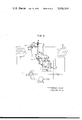
- FIG. 7 is a sectional view, on an enlarged scale, of the branching portion of the inlet pipe of the pilot heat exchanger shown in FIG. 6;
- FIG. 8 is a sectional view, on an enlarged scale, of the branching portion of the outlet pipe of the pilot heat exchanger shown in FIG. 6;
- FIG. 9(a) and FIG. 9(b) are views in explanation of the essential portions shown in FIG. 7;
- FIG. 10 is a schematic view, on an enlarged scale, of the accumulator of the refrigerating apparatus shown in FIG. 6;
- FIG. 11 is a schematic view of another form of outlet pipe shown in FIG. 10.
- FIG. 1 shows a cooling and heating system of the compression refrigeration type which comprises a compressor 1, a four-way change-over valve 2, an outdoor heat exchanger 5 (hereinafter referred to as an outdoor coil), a receiver 6c, an automatic expansion valve of the temperature responsive type 4 (hereinafter referred to as an expansion valve), a room heat exchanger 3 (hereinafter referred to as a room coil), and an accumulator of the thermal exchanger type 6 (hereinafter referred to as an accumulator).
- the aforementioned parts are connected together in the indicated order to constitute a refrigeration circuit which is known.
- a pilot heat exchanger 7 and four-way change-over means 9 which are characterizing features of the invention are inserted in the known refrigeration circuit to form a refrigeration circuit shown in the figure.
- the compressor 1 Upon actuation of the four-way change-over valve 2, the compressor 1 is connected at its outlet side either to the outdoor coil 5 or the room coil 3 acting as a condenser, and the accumulator 6 is connected at its inlet side either to the room coil 3 or the outdoor coil 5 acting as an evaporator.
- the four-way change-over means 9 comprises four check valves 8, 8, 8 and 8 connected together to form a bridge circuit.
- Ends A and D of a pair of opposed connecting pipes are connected to an end of the room coil 3 on a side thereof opposite the four-way change-over valve 2 and to an end of the outdoor coil 5 on a side thereof opposite the four-way change-over valve 2, respectively.
- Ends C and B of another pair of opposed connecting pipes are connected to an outlet of the expansion valve 4 and to an inlet of a finned tube 7b serving as a higher pressure side refrigerant passageway in the pilot heat exchanger 7, respectively.
- a refrigerant flowing in a stream through the expansion valve 4, pilot heat exchanger 7 and accumulator 6 flows in a predetermined direction at all times, even if the direction of flow of the steam of refrigerant through the room coil 3 and outdoor coil 5 when a cooling operation is perfomed is reversed from the direction of flow thereof when a heating operation is performed.
- FIG. 2 shows, on an enlarged scale, the accumulator 6 and pilot heat exchanger 7.
- the accumulator 6 comprises a main body 6a serving as a lower pressure side refrigerant passageway, a heat exchange coil 6b (See FIG. 1) arranged transversely in a lower portion of the main body 6a, and a receiver 6c serving as a higher pressure side refrigerant passageway and inserted in airtight relation from above into the main body 6a to be disposed above the heat exchange coil 6b.
- the main body 6a has an outlet pipe 14 projecting from the upper portion of its side wall and an oil return pipe 6e projecting from the lower portion thereof, the oil return pipe 6e being connected to the outlet pipe 14 outside the main body 6a.
- an inlet pipe 13 extends through the receiver 6c and has an opening at its lower end which is disposed above the heat exchange coil 6b, and the receiver 6c is connected at its lower portion to the heat exchange coil 6b at its upper end.
- the heat exchange coil 6b is connected at its lower end to the expansion valve 4 at its inlet, and the inlet pipe 13 is connected to the four-way change-over valve 2.
- the outlet pipe 14 is connected to the suction side of the compressor 1 directly and to the expansion valve 4 through an equalizing pipe 10 (See FIG. 1).
- the pilot heat exchanger 7 which is one of the features of the invention, comprises a main body 7a connected to the inlet pipe 13 through a minor diameter inlet pipe 11 and to the outlet pipe 14 through a minor diameter outlet pipe 12, so that the pilot heat exchanger 7 consitututes a bypass with respect to the accumulator 6.
- the pilot heat exchanger 7 further comprises a finned tube 7b disposed in the main body 7a to extend therethrough along its longitudinal axis and interposed between the connecting pipe end B and the upper portion of the receiver 6c, so that heat exchange can take place between the refrigerant under lower pressure passing through the main body 7a and the refrigerant under higher pressure passing through the finned tube 7b.
- the expansion valve 4 has a temperature sensing member 4a mounted in the minor diameter outlet pipe 12 and serving as a control temperature detecting element.
- the member 4a detects the temperature of the refrigerant in a gaseous state and under lower pressure that has been subjected to heat exchange with the refrigerant under higher pressure at the pilot heat exchanger 7, and permits the degree of opening of the expansion valve 4 to be automatically adjusted accordingly.
- a suitable refrigerant in a gaseous state and under higher pressure is discharged from the compressor 1 and passes through the four-way change-over valve 2 to the outdoor coil 5 which functions as a condenser.
- the major portion of the refrigerant is changed to a liquid state so that the refrigerant may have a dryness X which is ⁇ 0.05, for example.
- the refrigerant in a liquid state passes through the connecting pipe ends D and B into the finned tube 7b of the pilot heat exchanger 7 where it is cooled by heat exchange taking place between it and a portion of the refrigerant moving as a branch stream through the main body 7a after passing through the room coil 3 functioning as an evaporator.
- the cooled refrigerant is introduced into the receiver 6c.
- the cooled refrigerant is then subjected to further heat exchange at the heat exchange coil 6b in which is scattered the humid refrigerant disposed at the outlet of the room coil 3 functioning as an evaporator, so that it is changed to a supercooled refrigerant in a liquid state.
- the supercooled refrigerant in a liquid state passes through the expansion valve 4 and the connecting pipe ends C and A into the room coil 3.
- the supercooled refrigerant in a liquid state is subjected to heat exchange with the air in the room, so that it vaporizes and becomes a saturated refrigerant which may have a dryness X ⁇ 0.85, for example.
- the saturated refrigerant passes through the four-way change-over valve 2 and the major portion thereof is introduced into the main body 6a of the accumulator 6 through the inlet pipe 13.
- a minor portion of the saturated refrigerant passes through the minor diameter inlet pipe 11 into the main body 7a of the pilot heat exchanger 7.
- the major portion of the saturated refrigerant passing through the inlet pipe 13 serving as a heat exchange line is subjected to heat exchange with the supercooled refrigerant in a liquid state and under higher pressure in the receiver 6c, and scattered on to the heat exchange coil 6b with which it is subjected to further heat exchange.
- the portion of the refrigerant under lower pressure passing through the minor diameter inlet pipe 11 into the pilot heat exchanger 7 is superheated, as aforementioned, by the refrigerant disposed in the outlet of the condenser (outdoor coil 5) and flowing through the finned tube 7b.
- the saturated gas discharged from the accumulator 6 is mixed with oil passing through the oil return pipe 6e, and combined at the outlet line 14 with the superheated gas discharged from the pilot heat exchanger 7.
- the gas is returned to the suction side of the compressor 1, thereby completing a cooling cycle.
- the aforementioned cycle is repeated.
- the degree to which a portion of the refrigerant disposed at the outlet of the evaporator is superheated in the pilot heat exchanger 7 is detected by the temperature sensing member 4a mounted in the minor diameter outlet pipe 12.
- the member 4a produces a control signal which adjusts the degree of opening of the expansion valve 4, so that the room coil 3 functioning as an evaporator can operate in humid condition at all times and the efficiency of the system can be increased.
- the manner in which control of the expansion valve is effected is subsequently to be described in detail.
- a heating cycle will now be described.
- the refrigerant follows a path of movement indicated by solid line arrows.
- the refrigerant passes through the expansion valve 4, accumulator 6 and pilot heat exchanger 7 in the same direction as in the cooling cycle, and that the refrigerant is controlled and heat exchange is carried out in the same manner as aforementioned, except for the fact that the refrigerant passes through the outdoor coil 5 and room coil 3 in the opposite direction so that the former functions as an evaporator and the latter functions as a condenser.
- G 1 is the volume of the circulating refrigerant under lower pressure passing through the pilot heat exchanger 7
- G 2 is the volume of the circulating refrigerant under lower pressure introduced into the accumulator.
- the ratio of G 1 to G 2 is set such that G 1 :G 2 ⁇ 1:10 to 1:20.
- Heat exchange takes place at the heat exchange coil 6b between the refrigerant under lower pressure i 6 disposed at the outlet of the room coil 3 and having a dryness X ⁇ 0.85 and the refrigerant under higher pressure i 2 disposed at the outlet of the tube 7b of the pilot heat exchanger 7 and having a dryness X ⁇ 0.05.
- the heat balance can be given by
- X is the dryness of the refrigerant
- i 1 is the enthalpy of the refrigerant about to be introduced into the expansion valve 4
- i 2 is the enthalpy of the refrigerant disposed at the outlet of the pilot heat exchanger 7 or the inlet of the receiver 6c
- i 6 is the enthalpy of the refrigerant disposed at the outlet of the room coil 3
- i 7 is the enthalpy of the refrigerant disposed in the outlet pipe 14 of the accumulator 6.
- i 3 is the enthalpy of the refrigerant disposed at the outlet of the outdoor coil 5 functioning as a condenser or at the inlet of the finned tube 7b of the pilot heat exchanger 7, and i 8 is the enthalpy of the refrigerant disposed in the minor diameter outlet pipe 12.
- the degree of superheating (T 8 - T 7 ) of the refrigerant passing through the minor diameter outlet pipe 12 of the pilot heat exchanger 7 can be readily set at about 5°C.
- T 8 is the temperature of the refrigerant in the minor diameter outlet pipe 12 of the pilot heat exchanger 7
- T 7 is that of the refrigerant in the outlet pipe 14 of the accumulator 6.
- the gas drawn by suction into the compressor 1 is a mixture of the superheated refrigerant G 1 .i 8 disposed in the minor diameter outlet pipe 12 of the pilot heat exchanger 7 and the saturated refrigerant G 2 .i 7 disposed in the outlet pipe 14 of the accumulator 6. Since G 1 :G 2 ⁇ 1:10 to 1:20 and G 1 is smaller in volume than G 2 as aforementioned, the gas drawn by suction into the compressor 1 might as well be considered to be substantially in a saturated gaseous state.
- the expansion valve 4 for adjusting the volume of the refrigerant circulating through the refrigeration circuit is controlled by the temperature sensing member 4a adapted to sense the temperature of the refrigerant under lower pressure i 8 disposed at the outlet of the pilot heat exchanger 7.
- the enthalpy of the refrigerant i 8 disposed at the outlet of the pilot heat exchanger 7 also becomes greater. Accordingly, the degree of superheating of the refrigerant also rises.
- the temperature sensing member 4a senses this and produces a signal to increase the degree of opening of the expansion valve 4 so as to increase the rate of flow of the refrigerant.
- the portion of the refrigerant having a dryness X ⁇ 0.85 and disposed at the outlet of the room coil 3 functioning as an evaporator is brought, at the pilot heat exchanger 7, into heat exchange relationship with the refrigerant disposed at the outlet of the outdoor coil 5 functioning as a condenser, and the expansion valve 4 can be controlled by using the temperature of the superheated refrigerant under lower pressure as an element to be detected, whereby the volume of the refrigerant in circulation passing through the expansion valve can be controlled.
- This control system has the effect of maintaining the dryness of the refrigerant disposed at the outlet of the room coil 3 functioning as an evaporator at a level such that the refrigerant is in a saturated gaseous state and has a suitable humidity at all times regardless of changes in the load applied to the evaporator. This makes it possible to make full use of the heat transfer area of the room coil functioning as an evaporator because vaporization of the refrigerant takes place in all the area of the coil.
- the refrigerant disposed at the outlet of the outdoor coil 5 functioning as a condenser can also be made into a flash gas state.
- effective use can be made of the heat transfer area of the outdoor coil 5.
- the outdoor coil 5 functions as a condenser and the room coil 3 functions as an evaporator. It is to be understood that the control system can achieve the same effect when the four-way change-over valve 2 is actuated such that the room coil 3 functions as a condenser and the outdoor coil 5 functions as an evaporator.
- the provision of the four-way change-over means 9 according to the invention offers an advantage in that control can be effected by using only one expansion valve in a refrigerating apparatus of the reversible refrigeration cycle.
- the difference in temperature between the refrigerant at the inlet of the pilot heat exchanger 7 and the refrigerant at the outlet thereof can be detected as an electric change which can be converted into a mechanical displacement, so that the flow rate of the refrigerant can be controlled.
- the refrigerant under higher pressure disposed between the four-way change-over means 9 and the receiver 6 is used as a heat source for effecting heat exchange with a portion of the refrigerant under lower pressure. It is to be understood that the invention is not limited to the aforementioned refrigerant under higher pressure and that any refrigerant under higher pressure disposed between the heat exchanger functioning as a condenser and the expansion valve 4 can be used as a heat source.
- FIG. 4 shows another embodiment of the invention in which the refrigerant under higher pressure is replaced by an electric heater 7c which is hermetically inserted in the pilot heat exchanger 7 to serve as a heat source for effecting heat exchange with a portion of the refrigerant under lower pressure disposed at the outlet of the room coil 3.
- heat exchange takes place between the refrigerant under lower pressure flowing through the main body 7a and the heat generated by the electric heater 7c.
- this embodiment will be omitted because the embodiment differs from the embodiment shown in FIG. 2 in the following point only.
- heat exchange takes place between the portion of the refrigerant under lower pressure (G 1 .i 6 ) and the heat generated by the electric heater 7c.
- the capacity Y (kw) of the electric heater 7c is given by
- FIG. 5 shows a Mollier diagram in explanation of this embodiment.
- FIG. 6 shows still another embodiment of the invention in which the compressor 1, four-way change-over valve 2, outdoor coil 5, receiver 6c, expansion valve 4, room coil 3 and accumulator 6 are connected together in the indicated order to constitute a refrigeration circuit.
- the embodiment shown in FIG. 6 further comprises, in addition to the known components of the refrigeration circuit, the pilot heat exchanger 7 and the four-way change-over means 9 which are characterizing features of the invention.
- the two embodiments differ from each other in the detailed construction of the four-way change-over means 9, pilot heat exchanger 7, receiver 6c and accumulator 6. The differences will presently be described.
- the four-way change-over means 9 comprises two change-over ports A and D, one inlet port C and one outlet port B and constitutes a change-over valve which automatically connects the port A or D of the higher pressure to the outlet port B and the port D or A of the lower pressure to the inlet port C.
- the change-over port A is connected to the liquid line side of the room coil 3;
- the change-over port D is connected to the liquid line side of the outdoor coil 5;
- the outlet port B is connected, through the higher pressure side of the pilot heat exchanger 7, to the upper layer of the interior of the receiver 6c; and the inlet port C is connected to the outlet of the expansion valve 4.
- the accumulator 6 is constructed integrally with the receiver 6c, with the former being hermetically housed in the latter with their top walls being disposed at the same level.
- a heat exchange coil 15 is disposed transversely in a lower portion of the accumulator 6 which is on the lower pressure side.
- the inlet pipe 13 connected to the four-way change-over valve 2 extends through the top wall of the accumulator 6 and opens in an upper portion of the accumulator 6, and the outlet pipe 14 connected to the suction side of the compressor 1 also extends through the top wall of the accumulator 6 into the accumulator where it is bent substantially in the form of a letter U, with the lower portion of the U-shaped outlet pipe 14 being immersed in the refrigerant in the liquid state disposed on the bottom of the accumulator and the upper open end of one leg of the letter U opening in the refrigerant in a gaseous state disposed in the upper portion of the accumulator 6.
- the inlet pipe 6g is connected to the higher pressure side of the pilot heat exchanger 7 as aforementioned and an outlet pipe opens at one end in a lower portion of the receiver 6c and is connected at the other end to the heat exchange coil 15 in the accumulator 6.
- the heat exchange coil 15 is connected to the inlet of the expansion valve 4 through a riser disposed along the side wall of the accumulator 6.
- the pilot heat exchanger 7 which is compact in size may be constructed as a double wall tubular structure and comprise an outer tube 7d which permits all the refrigerant uner higher pressure disposed between the condenser and the receiver 6c to pass therethrough, and an inner tube 7e which permits a portion of the refrigerant under lower pressure to pass therethrough.
- the inner tube 7e is connected at its opposite ends to the minor diameter inlet pipe 11 and the minor diameter outlet pipe 12 to the inlet pipe 13 and the outlet pipe 14 of the accumulator 6 respectively, so that the minor diameter pipes bypass the accumulator.
- the temperature sensing member 4a for controlling the expansion valve 4 is mounted in the minor diameter outlet pipe 12 connected to the outlet pipe 14 and detects the degree of superheating of the refrigerant gas under lower pressure that has been subjected to heat exchange with the refrigerant under higher pressure in the pilot heat exchanger 7 so as to adjust the degree of opening of the expansion valve 4 accordingly.
- FIG. 7 and FIG. 8 An inlet portion a and an outlet portion b at which the minor diameter inlet pipe 11 and the minor diameter outlet pipe 12 are connected to the inlet pipe 13 and the outlet pipe 14 of the accumulator 6 respectively are shown in FIG. 7 and FIG. 8 on an enlarged scale. As shown, these portions each have a novel construction which is characteristic of the invention. Particularly, the inlet portion a is an outstanding feature of the invention.
- the inlet pipe 13 is arranged vertically and the minor diameter inlet pipe 11 disposed normal to the longitudinal axis of the inlet pipe 13 is inserted at one end portion thereof in the inlet pipe 13 in right angle and airtight relationship in such a manner that, as shown in FIG.
- the center line XX of a transverse sectional plane of the inlet pipe 13 coincides with the center line YY of a vertical sectional plane of the end portion of the minor diameter inlet pipe 11.
- the minor diameter inlet pipe 11 is closed at its front end and formed with at least two orifices 16, 16 in a portion of the wall of the pipe 11 which is disposed in the stream of refrigerant passing through the inlet pipe 13, so that a portion of the refrigerant under lower pressure passing through the inlet pipe 13 can be introduced through the orifices 16, 16 into the minor diameter inlet pipe 11 at a constant ratio with respect to all the refrigerant in circulation.
- the positions of the orifices 16, 16 must meet a certain requirement.
- the requirement is that, when the orifices 16, 16 are two in number, they are formed at points at which the circumference of an imaginary circle D 1 intersects the longitudinal center axis of the minor diameter inlet pipe 11.
- the outlet port 14 is arranged perpendicularly in the refrigerating apparatus as is the case with the inlet pipe 13, and the minor diameter outlet pipe 12 disposed normal to the longitudinal axis of the outlet pipe 14 is hermetically inserted at one end portion thereof in the pipe 14 as is the case with the pipe 11.
- the end portion of the pipe 12 inserted in the pipe 14 is cut obliquely at its front end 12a such that the angle ⁇ formed by the front end 12a and the wall of the pipe 12 is less than 45° or an acute angle so as to increase the area of opening of the pipe 12 in the pipe 14.
- the pipe 12 is disposed such that the oblique front end 12a faces the downstream side of the refrigerant passing through the outlet pipe 14.
- the inlet portion a and the outlet portion b of the pilot heat exchanger 7 is constructed as aforementioned, it is possible to disregard a change in the flow rate of the refrigerant due to a variation in the length of the minor diameter inlet pipe and minor diameter outlet pipe.
- the condition of the refrigerant in the pilot heat exchanger 7 can be detected with a high degree of precision and the refrigerating apparatus can be controlled positively as subsequently to be described.
- the construction of the accumulator 6 is shown on an enlarged scale in FIG. 10.
- the lower portion of the U-shaped outlet pipe 14 is disposed below the heat exchange coil 15, and an oil return aperture 17 is formed at the bottom of the U-shaped outlet pipe 14.
- an orifice 18 is formed in one leg of the U-shaped outlet pipe 14 which is disposed on the refrigerant outlet side for the oil return aperture 17.
- the orifice 18 which is larger in dimension than the oil return aperture 17 is formed in a position such that it is disposed at the maximum level of the refrigerant in a liquid state.
- the orifice 18 is formed in the form of a hole as shown in FIG. 10 but the outlet pipe 14 may have orifices 18' each which is formed in the form of a slit as shown in FIG. 11.
- the orifice 18 as well as the orifice 18' is formed in a portion of the wall of the pipe 14 which is disposed on the downstream side of the oil return aperture 17. It should be understood, however, that the orifice 18 or 18' may be provided on the upstream side of the oil return aperture 17.
- Other modifications will be apparent to one of ordinary skill in the art without departing from the scope and spirit of the invention.
- FIG. 6 to FIG. 11 The operation of the cooling and heating system constructed as aforementioned (FIG. 6 to FIG. 11) will now be described. The description of the operation which is similar to those of other embodiments (FIG. 1 to FIG. 5) will be omitted, and the description will be confined to the features of the embodiment shown in FIG. 6 to FIG. 11.
- the inlet pipe 13 and the outlet pipe 14 of the accumulator 6 are arranged perpendicularly, and the orifices formed in the minor diameter inlet pipe 11 for introducing the refrigerant therethrough into the pilot heat exchanger 7 and the open end 12a of the minor diameter outlet pipe 12 through which the refrigerant is discharged from the pilot heat exchanger 7 each have a special construction.
- the refrigerant introduced into the inner tube 7e is uniform in state in cross-section when passing through the minor diameter inlet pipe, and the refrigerant drawn by suction into the minor diameter inlet pipe 11 branching off the inlet pipe 13 and connected to the pilot heat exchanger 7 is at a constant ratio in volume to all the refrigerant in circulation.
- the refrigerant is discharged through the outlet pipe 12 without any resistance being offered thereto.
- control of the refrigerant can be effected with a high degree of precision by detecting the degree of superheating of the refrigerant under lower pressure regardless of changes in the load.
- the operation of the accumulator 6 will now be described. If the liquid level in the accumulator 6 rises above the orifice 18 as a result of a change in the load, then the refrigerant is drawn by suction in relatively large volumes through the oil return aperture 17 and the orifice 18 which is larger in dimension than the aperture 17. If the liquid level in the accumulator 6 falls below the orifice 18, then the refrigerant is drawn by suction in relatively small volumes through the oil return aperture 17 only.
- the refrigerant in a liquid state drawn by suction through the oil return aperture 17 and the orifice 18 is very small in volume as compared with the refrigerant in a gaseous state drawn by suction through the U-shaped outlet pipe, so that the refrigerant in a liquid state is immediately converted into a gaseous state by the heat of the gas in the accumulator 6 as soon as it is drawn by suction through the U-shaped pipe. This entirely eliminates the hazard of the refrigerant in a liquid state being drawn by suction into the compressor 1.
- the system since the heat exchange coil 15 is immersed in the refrigerant in a liquid state at all times, the system has a constant heat transfer rate which is at a high level and the dry gas can be returned to the compressor in a stable manner.
- the refrigerating apparatus can be operated in a stable manner and with a high degree of efficiency.
- the liquid level in the accumulator 6 can be controlled positively without being affected by the drawing of a mixture of oil and refrigerant by suction through the oil return aperture 17, and the oil can be returned satisfactorily to ensure smooth operation of the compressor 1 because the oil disposed on the liquid level can be returned.
- the heat source for the accumulator 6 in this embodiment is not limited to the refrigerant under higher pressure passing through the heat exchange coil 15, and that an electric heater or other heat source may be used as is the case with the previously described embodiments.
- the temperature sensing member 4a is mounted in the minor diameter outlet pipe 12 for producing a signal to adjust the degree of opening of the expansion valve 4, in order that the degree of superheating of a portion of the refrigerant in the room coil 3 can be set at a predetermined level by using the pilot heat exchanger in the same manner as in the embodiment shown in FIG. 1.
- the pilot heat exchanger 7 is mounted such that it constitutes a bypass of the accumulator so that heat exchange may take place between a portion of the refrigerant disposed at the outlet of the heat exchanger functioning as an evaporator and the refrigerant disposed at the outlet of the heat exchanger functioning as a condenser.
- the degree of opening of the expansion valve 4 is adjusted in accordance with the degree of superheating of the refrigerant under lower pressure disposed at the outlet of the pilot heat exchanger 7, whereby the evaporator can be made to function in humid condition at all times regardless of changes in the load.
- the dryness of the refrigerant at the outlet of the evaporator can be set at a predetermined level at which about 85 percent of the refrigerant is converted into a gaseous state and about 15 percent thereof remains in a liquid state.
- the refrigerant in the humid state is brought to heat exchange relation with the refrigerant under higher pressure in the accumulator 6 so that the refrigerant drawn by suction into the compressor 1 may be converted into a saturated gas.
- the evaporator operates in humid condition at all times regardless of changes in the load.
- This permits all the heat transfer area of the evaporator to be utilized for vaporizing the refrigerant in a liquid state, with a result that the coefficient of heat transmission of the evaporator is improved.
- the invention is conductive to higher capabilities of the apparatus when the heat exchange area remains the same and to reduced heat exchange area when the capabilities of the apparatus remain the same, thereby permitting to reduce cost.
- control is effected such that the evaporator operates in a humid condition at all times regardless of changes in the load, and there is almost no change in the heat transfer area of the evaporator even if a change occurs in the load.
- the degree of opening of the expansion valve has only to be adjusted in accordance with a change in the load, because there is almost no change in the coefficient of heat transmission.
- the degree of opening of the expansion valve 4 is stabilized and the valve is free from the hunting phenomenon.
- the evaporator is made, as aforementioned, to operate in humid condition at all times regardless of changes in the load, so that separation of the refrigerating apparatus oil from the refrigerant and stagnation thereof in the evaporator can be prevented.
- the oil return aperture 17 and the orifice 18 are formed in the outlet pipe 14 of the accumulator 6 to facilitate oil return to the compressor 1, thereby eliminating the need to provide oil return means of special construction.
- the refrigerant in humid condition in the evaporator is heated and completely vaporized in the accumulator 6 into a dry saturated gas which is mixed at the outlet of the accumulator 6 with the refrigerant in a gaseous state which has been superheated in the pilot heat exchanger 7, so that the mixture is drawn by suction into the compressor. Since the superheated refrigerant in a gaseous state is very small in volume as compared with all the refrigerant in circulation, the refrigerant in a gaseous state drawn into the compressor 1 is not superheated and it is substantially in a saturated gaseous state.
- control of the evaporator is effected by the expansion valve 4 disposed immediately before the evaporator. This makes it possible to effect control in a stable manner by responding quickly to a change in the load.
- the conventional system of adjusting the degree of supercooling of the refrigerant at the outlet of the condenser by detecting the state of the refrigerant at the outlet of the evaporator brought about by a change in the load may be said to effect indirect control, as compared with the system according to the invention in which the evaporator is directly controlled to cope with a change in the load applied to the evaporator.
- the conventional system is slow in responding to a change in the load.
- the conventional supercooling system is unable to effect control in a stable manner.
- the outlet of the condenser and the inlet of the expansion valve are sealed by the refrigerant in a supercooled liquid state. It is thus necessary to accumulate the refrigerant in a liquid state in the condenser. This is conductive to reduced capabilities and increased size of the condenser, and the charge of the refrigerant is increased accordingly.
- the refrigerant at the outlet of the condenser can be controlled such that it is maintained in a flash gas state, because the refrigerant can be cooled in the pilot heat exchanger 7 and the accumulator 6.
- This makes it possible to make effective use of the heat transfer area of the condenser as well as the heat transfer area of the evaporator, so that it is possible to reduce the size of the condenser. Since no refrigerant in a liquid state is accumulated in the condenser, the charge of the refrigerant in the apparatus can be greatly reduced, thereby reducing the cost of the refrigerating apparatus.
- the pressure required for condensation of vapor is lower than in a refrigerating apparatus using the aforementioned conventional control system, so that the condenser can tolerate an application of an overload.
- the refrigerant at the outlet of the evaporator is higher in pressure when the control system according to the invention is used than when the conventional superheated gas system is used, so that frost formation can be prevented.
- the pilot heat exchanger 7 used in the control system which can achieve the aforementioned specific results has only to have a capacity large enough to superheat a portion of the refrigerant under lower pressure. Therefore, it is possible to use the pilot heat exchanger of a very small size and of very simple construction, such as a double tube structure, irrespective of the capacity of the refrigerating apparatus. This is conductive to reduced cost.
- the refrigerant under higher pressure interposed between the heat exchanger functioning as a condenser and the expansion valve 4 may be used as a heat source with which a portion of the refrigerant under lower pressure is brought into heat exchange relationship in the pilot heat exchanger 7, and such refrigerant under higher pressure may be introduced into the heat exchanger 7 from any source as desired.
- the refrigerant coming out of the condenser can be changed to a saturated liquid state if it is a flash gas, and into a supercooled liquid state if it is in a saturated liquid state, by the heat exchange taking place in the pilot heat exchanger.
- a heat generating member other than the refrigerant under higher pressure can be used as a heat source for the heat exchanger.
- the heat source of the pilot heat exchanger has only to have a capacity large enough to heat a portion of the refrigerant disposed at the outlet of the evaporator. This means that such heat source has a small capacity and that the amount of heat generated by it can be adjusted readily. This makes it possible to effect control with a high degree of precision.
- the inlet pipe 13 connected to the pilot heat exchanger 7 branching off the inlet pipe 13 at the entrance to the accumulator 6 is formed therein with two or more orifices of even number which are disposed in positions such that a portion of the refrigerant which is at a constant ratio with respect to the refrigerant passing through the inlet pipe 13 can be deflected from its course and introduced into the pilot heat exchanger 7.
- the branch stream of refrigerant under lower pressure which is at a constant ratio in volume to the main stream of refrigerant under lower pressure to pass through the pilot heat exchanger 7 regardless of changes in the load or variations in the length of line to the pilot heat exchanger 7.
- control of capabilities of the apparatus can be effected in a stable manner without the expansion valve 4 suffering from hunting.
- the inlet pipe 13 of the accumulator 6 connected to an intake portion of the minor diameter inlet pipe connected to the pilot heat exchanger 7 is disposed perpendicularly in the refrigerating apparatus.
- the minor diameter outlet pipe 12 has an acute-angled end 12a which opens on the downstream side of the refrigerant passing through the outlet pipe 14. This permits the refrigerant to move out of the minor diameter outlet pipe 12 into the outlet pipe 14 with least resistance. Thus, control of capabilities of the apparatus can be effected in a stable manner.
- the outlet pipe 14 connecting the accumulator 6 to the compressor 1 is formed in the shape of a letter U, with the open end of one leg of the U-shaped pipe 14 being disposed in the refrigerant in a gaseous state in the accumulator 6 and the bottom portion of the U-shaped pipe 14 being disposed in the lower portion of the accumulator 6.
- the oil return aperture 17 is formed in the bent bottom portion of the U-shaped pipe 14, while the orifice 18 is formed in the other leg of the U-shaped pipe 14 in a position which is disposed above the heat exchange coil 15.
- This arrangement enables the evaporator disposed anterior to the accumulator 6 to operate such that the refrigerant at the outlet of the evaporator is in a state of humid saturated gas, so that all the heat transfer area of the evaporator can be utilized for performing a vaporization action. At the same time, it enables the refrigerant in a dry gaseous state to be returned to the compressor 1. Thus, the capabilities of the refrigerating apparatus can be maximized.
- the orifice 18 is formed in the U-shaped outlet pipe 14 in a position which is disposed above the heat exchange coil 15.
- the refrigerating apparatus can be operated as a reversible apparatus of the heat pump type by mounting the four-way change-over valve 2 and the four-way change-over means 9 in the apparatus.
- the stream of refrigerant moving through the pilot heat exchanger 7, receiver 6c, expansion valve 4 and accumulator 6 can be controlled such that the refrigerant flows in the same direction, even if the refrigerant flows in one direction through the room coil and outdoor coil of the refrigeration circuit when the apparatus performs a cooling operation and flows in the opposite direction when it performs a heating operation. This eliminates the need to use an additional expansion valve and only one expansion valve 4 can do the job, thereby reducing cost.
- the outdoor coil 5 functioning as a condenser when the apparatus performs a cooling operation functions as an evaporator when the apparatus performs a heating operation. This permits to reduce the size of the outdoor coil without reducing its performance as a condenser, because control is effected such that no refrigerant in a liquid state is accumulated therein when it functions as a condenser in the cooling operation.
Landscapes
- Engineering & Computer Science (AREA)
- Physics & Mathematics (AREA)
- Mechanical Engineering (AREA)
- Thermal Sciences (AREA)
- General Engineering & Computer Science (AREA)
- Chemical & Material Sciences (AREA)
- Analytical Chemistry (AREA)
- Power Engineering (AREA)
- Compression-Type Refrigeration Machines With Reversible Cycles (AREA)
Applications Claiming Priority (4)
| Application Number | Priority Date | Filing Date | Title |
|---|---|---|---|
| JP10720773A JPS5320145B2 (cg-RX-API-DMAC7.html) | 1973-09-21 | 1973-09-21 | |
| JA48-107206 | 1973-09-21 | ||
| JA48-107207 | 1973-09-21 | ||
| JP10720673A JPS533817B2 (cg-RX-API-DMAC7.html) | 1973-09-21 | 1973-09-21 |
Publications (1)
| Publication Number | Publication Date |
|---|---|
| US3938349A true US3938349A (en) | 1976-02-17 |
Family
ID=26447256
Family Applications (1)
| Application Number | Title | Priority Date | Filing Date |
|---|---|---|---|
| US05/503,507 Expired - Lifetime US3938349A (en) | 1973-09-21 | 1974-09-05 | Refrigerating apparatus with superheat control |
Country Status (5)
| Country | Link |
|---|---|
| US (1) | US3938349A (cg-RX-API-DMAC7.html) |
| DE (1) | DE2445065C3 (cg-RX-API-DMAC7.html) |
| FR (1) | FR2244971B1 (cg-RX-API-DMAC7.html) |
| GB (1) | GB1464453A (cg-RX-API-DMAC7.html) |
| IT (1) | IT1019334B (cg-RX-API-DMAC7.html) |
Cited By (37)
| Publication number | Priority date | Publication date | Assignee | Title |
|---|---|---|---|---|
| US4045977A (en) * | 1976-09-09 | 1977-09-06 | Dunham-Bush, Inc. | Self operating excess refrigerant storage system for a heat pump |
| DE2709343A1 (de) * | 1976-03-05 | 1977-09-15 | Hitachi Ltd | Gegenstrom-klimaanlage |
| FR2369510A1 (fr) * | 1976-11-02 | 1978-05-26 | Sundstrand Corp | Dispositif de commande integree pour pompes a chaleur |
| US4187695A (en) * | 1978-11-07 | 1980-02-12 | Virginia Chemicals Inc. | Air-conditioning system having recirculating and flow-control means |
| EP0038374A1 (en) * | 1980-04-18 | 1981-10-28 | Monseol Limited | A compression refrigerator unit adjustable in accordance with the liquid flowing out from the evaporator |
| EP0142209A3 (en) * | 1983-11-11 | 1985-12-04 | Grasso's Koninklijke Machinefabrieken N.V. | Plant, such as cooling plant or heat pump |
| US4785639A (en) * | 1986-05-20 | 1988-11-22 | Sundstrand Corporation | Cooling system for operation in low temperature environments |
| US5040380A (en) * | 1988-08-04 | 1991-08-20 | Super S.E.E.R. Systems Inc. | Method and apparatus for the sensing of refrigerant temperatures and the control of refrigerant loading |
| US5396776A (en) * | 1992-10-22 | 1995-03-14 | Samsung Electronics Co., Ltd. | Dual-purpose cooling/heating air conditioner and control method thereof |
| US5651265A (en) * | 1994-07-15 | 1997-07-29 | Grenier; Michel A. | Ground source heat pump system |
| US5799499A (en) * | 1995-09-27 | 1998-09-01 | Fujikoki Corporation | Combined unit of expansion valve and reservoir tank |
| EP1087192A1 (en) * | 1999-09-22 | 2001-03-28 | Carrier Corporation | Reversible heat pump with sub-cooling receiver |
| US20040261449A1 (en) * | 2003-06-24 | 2004-12-30 | Memory Stephen B. | Refrigeration system |
| US20040261447A1 (en) * | 2002-08-02 | 2004-12-30 | Hiromune Matsuoka | Refrigeration equipment |
| US20050217312A1 (en) * | 2004-04-02 | 2005-10-06 | Tekair Lp | Refrigerant receiving apparatus |
| US20070006602A1 (en) * | 2003-06-13 | 2007-01-11 | Koji Hayashi | Freezer apparatus |
| US20090025404A1 (en) * | 2007-07-23 | 2009-01-29 | Hussmann Corporation | Combined receiver and heat exchanger for a secondary refrigerant |
| EP1512924A3 (en) * | 2003-09-05 | 2011-01-26 | LG Electronics, Inc. | Air conditioner comprising heat exchanger and means for switching cooling cycle |
| US20140013780A1 (en) * | 2009-02-18 | 2014-01-16 | Emerson Climate Technologies, Inc. | Condensing unit having fluid injection |
| US20140165646A1 (en) * | 2011-07-19 | 2014-06-19 | Sascha Hellmann | Oil Compensation In A Refrigeration Circuit |
| US20140373560A1 (en) * | 2013-06-24 | 2014-12-25 | Ford Global Technologies, Llc | Internal Heat Exchanger with Integrated Receiver/Dryer and Thermal Expansion Valve |
| US20180094843A1 (en) * | 2016-09-30 | 2018-04-05 | Bergstrom, Inc. | Refrigerant Liquid-Gas Separator Having an Integrated Check Valve |
| CN108061404A (zh) * | 2017-08-28 | 2018-05-22 | 浙江大学 | 一种双向混合工质热泵系统 |
| CN108061400A (zh) * | 2017-08-28 | 2018-05-22 | 浙江大学 | 一种可切换的双向混合工质热泵系统 |
| CN108061403A (zh) * | 2017-08-28 | 2018-05-22 | 浙江大学 | 一种双向自复叠热泵系统 |
| CN108072202A (zh) * | 2017-08-28 | 2018-05-25 | 浙江大学 | 一种热泵用的桥式双向自复叠系统 |
| CN108826541A (zh) * | 2018-05-11 | 2018-11-16 | 浙江大学 | 一种带回热器的除湿换热器热泵空调系统及其运行方法 |
| US20180363965A1 (en) * | 2016-02-24 | 2018-12-20 | AGC Inc. | Refrigeration cycle apparatus |
| US10589598B2 (en) | 2016-03-09 | 2020-03-17 | Bergstrom, Inc. | Integrated condenser and compressor system |
| US10675948B2 (en) | 2016-09-29 | 2020-06-09 | Bergstrom, Inc. | Systems and methods for controlling a vehicle HVAC system |
| US10703173B2 (en) | 2016-08-22 | 2020-07-07 | Bergstrom, Inc. | Multi-compressor climate system |
| US10967709B2 (en) | 2015-03-09 | 2021-04-06 | Bergstrom, Inc. | Graphical user interfaces for remotely managing climate control systems of a fleet of vehicles |
| US11420496B2 (en) | 2018-04-02 | 2022-08-23 | Bergstrom, Inc. | Integrated vehicular system for conditioning air and heating water |
| US11448441B2 (en) | 2017-07-27 | 2022-09-20 | Bergstrom, Inc. | Refrigerant system for cooling electronics |
| US20230152016A1 (en) * | 2019-08-09 | 2023-05-18 | Carrier Corporation | Cooling system and method of operating a cooling system |
| US20230406067A1 (en) * | 2020-11-23 | 2023-12-21 | Valeo Systemes Thermiques | Thermal conditioning system for a motor vehicle |
| US12420616B2 (en) | 2016-08-22 | 2025-09-23 | Bergstrom, Inc. | Multi-compressor oil migration mitigation climate system |
Families Citing this family (6)
| Publication number | Priority date | Publication date | Assignee | Title |
|---|---|---|---|---|
| DE3139044C1 (de) * | 1981-10-01 | 1983-04-21 | Danfoss A/S, 6430 Nordborg | Kaelte- oder Waermepumpenkreislauf |
| GB2295888B (en) * | 1994-10-28 | 1999-01-27 | Bl Refrigeration & Airco Ltd | Heating and cooling system |
| CN2405489Y (zh) * | 1998-08-21 | 2000-11-15 | 郑海波 | 制冷座垫 |
| TR200702964T1 (tr) | 2004-11-05 | 2007-06-21 | Ar�El�K Anon�M ��Rket� | Bir soğutucu ve kontrol yöntemi |
| DE102009031467B4 (de) | 2009-07-01 | 2023-03-09 | Sew-Eurodrive Gmbh & Co Kg | Elektromotor mit Gehäuse und Kühlanordnung und Verfahren zum Kühlen |
| CN119042848B (zh) * | 2024-07-30 | 2025-10-14 | 浙江中广电器集团股份有限公司 | 一种利用压缩机废热回收增加系统吸气过热度的控制方法 |
Citations (2)
| Publication number | Priority date | Publication date | Assignee | Title |
|---|---|---|---|---|
| US3552140A (en) * | 1968-12-19 | 1971-01-05 | Westinghouse Electric Corp | Refrigeration system with accumulator |
| US3779031A (en) * | 1970-08-21 | 1973-12-18 | Hitachi Ltd | Air-conditioning system for cooling dehumidifying or heating operations |
Family Cites Families (4)
| Publication number | Priority date | Publication date | Assignee | Title |
|---|---|---|---|---|
| US3163998A (en) * | 1962-09-06 | 1965-01-05 | Recold Corp | Refrigerant flow control apparatus |
| US3381487A (en) * | 1966-09-26 | 1968-05-07 | Westinghouse Electric Corp | Refrigeration systems with accumulator means |
| US3423954A (en) * | 1967-11-13 | 1969-01-28 | Westinghouse Electric Corp | Refrigeration systems with accumulator means |
| US3643465A (en) * | 1968-09-16 | 1972-02-22 | Edward W Bottum | Refrigeration suction accumulator |
-
1974
- 1974-09-03 GB GB3846274A patent/GB1464453A/en not_active Expired
- 1974-09-05 US US05/503,507 patent/US3938349A/en not_active Expired - Lifetime
- 1974-09-19 IT IT53104/74A patent/IT1019334B/it active
- 1974-09-20 DE DE2445065A patent/DE2445065C3/de not_active Expired
- 1974-09-20 FR FR7431902A patent/FR2244971B1/fr not_active Expired
Patent Citations (2)
| Publication number | Priority date | Publication date | Assignee | Title |
|---|---|---|---|---|
| US3552140A (en) * | 1968-12-19 | 1971-01-05 | Westinghouse Electric Corp | Refrigeration system with accumulator |
| US3779031A (en) * | 1970-08-21 | 1973-12-18 | Hitachi Ltd | Air-conditioning system for cooling dehumidifying or heating operations |
Cited By (62)
| Publication number | Priority date | Publication date | Assignee | Title |
|---|---|---|---|---|
| DE2709343A1 (de) * | 1976-03-05 | 1977-09-15 | Hitachi Ltd | Gegenstrom-klimaanlage |
| US4045977A (en) * | 1976-09-09 | 1977-09-06 | Dunham-Bush, Inc. | Self operating excess refrigerant storage system for a heat pump |
| FR2369510A1 (fr) * | 1976-11-02 | 1978-05-26 | Sundstrand Corp | Dispositif de commande integree pour pompes a chaleur |
| US4100762A (en) * | 1976-11-02 | 1978-07-18 | Sundstrand Corporation | Integrated controls assembly |
| US4187695A (en) * | 1978-11-07 | 1980-02-12 | Virginia Chemicals Inc. | Air-conditioning system having recirculating and flow-control means |
| EP0038374A1 (en) * | 1980-04-18 | 1981-10-28 | Monseol Limited | A compression refrigerator unit adjustable in accordance with the liquid flowing out from the evaporator |
| EP0142209A3 (en) * | 1983-11-11 | 1985-12-04 | Grasso's Koninklijke Machinefabrieken N.V. | Plant, such as cooling plant or heat pump |
| US4785639A (en) * | 1986-05-20 | 1988-11-22 | Sundstrand Corporation | Cooling system for operation in low temperature environments |
| US5040380A (en) * | 1988-08-04 | 1991-08-20 | Super S.E.E.R. Systems Inc. | Method and apparatus for the sensing of refrigerant temperatures and the control of refrigerant loading |
| US5396776A (en) * | 1992-10-22 | 1995-03-14 | Samsung Electronics Co., Ltd. | Dual-purpose cooling/heating air conditioner and control method thereof |
| US5651265A (en) * | 1994-07-15 | 1997-07-29 | Grenier; Michel A. | Ground source heat pump system |
| US5799499A (en) * | 1995-09-27 | 1998-09-01 | Fujikoki Corporation | Combined unit of expansion valve and reservoir tank |
| EP1087192A1 (en) * | 1999-09-22 | 2001-03-28 | Carrier Corporation | Reversible heat pump with sub-cooling receiver |
| US6378323B1 (en) | 1999-09-22 | 2002-04-30 | Carrier Corporation | Reversible heat pump with sub-cooling receiver |
| US20040261447A1 (en) * | 2002-08-02 | 2004-12-30 | Hiromune Matsuoka | Refrigeration equipment |
| US7171825B2 (en) | 2002-08-02 | 2007-02-06 | Daikin Industries, Ltd. | Refrigeration equipment |
| US20070006602A1 (en) * | 2003-06-13 | 2007-01-11 | Koji Hayashi | Freezer apparatus |
| US7594409B2 (en) * | 2003-06-13 | 2009-09-29 | Daikin Industries, Ltd. | Freezer apparatus |
| US20040261449A1 (en) * | 2003-06-24 | 2004-12-30 | Memory Stephen B. | Refrigeration system |
| US6901763B2 (en) | 2003-06-24 | 2005-06-07 | Modine Manufacturing Company | Refrigeration system |
| WO2005010445A1 (en) * | 2003-06-24 | 2005-02-03 | Modine Manufacturing Company | Refrigeration system |
| EP1512924A3 (en) * | 2003-09-05 | 2011-01-26 | LG Electronics, Inc. | Air conditioner comprising heat exchanger and means for switching cooling cycle |
| US20050217312A1 (en) * | 2004-04-02 | 2005-10-06 | Tekair Lp | Refrigerant receiving apparatus |
| US7395678B2 (en) * | 2004-04-02 | 2008-07-08 | Parker-Hannifin Corp. | Refrigerant receiving apparatus |
| US20090025404A1 (en) * | 2007-07-23 | 2009-01-29 | Hussmann Corporation | Combined receiver and heat exchanger for a secondary refrigerant |
| US7900467B2 (en) | 2007-07-23 | 2011-03-08 | Hussmann Corporation | Combined receiver and heat exchanger for a secondary refrigerant |
| US20140013780A1 (en) * | 2009-02-18 | 2014-01-16 | Emerson Climate Technologies, Inc. | Condensing unit having fluid injection |
| US9494356B2 (en) * | 2009-02-18 | 2016-11-15 | Emerson Climate Technologies, Inc. | Condensing unit having fluid injection |
| US20140165646A1 (en) * | 2011-07-19 | 2014-06-19 | Sascha Hellmann | Oil Compensation In A Refrigeration Circuit |
| US9970695B2 (en) * | 2011-07-19 | 2018-05-15 | Carrier Corporation | Oil compensation in a refrigeration circuit |
| US9175883B2 (en) * | 2013-06-24 | 2015-11-03 | Ford Global Technologies, Llc | Internal heat exchanger with integrated receiver/dryer and thermal expansion valve |
| US20140373560A1 (en) * | 2013-06-24 | 2014-12-25 | Ford Global Technologies, Llc | Internal Heat Exchanger with Integrated Receiver/Dryer and Thermal Expansion Valve |
| US12304281B2 (en) | 2015-03-09 | 2025-05-20 | Bergstrom, Inc. | Systems and methods of managing a power source of a vehicle |
| US11780292B2 (en) | 2015-03-09 | 2023-10-10 | Bergstrom, Inc. | Graphical user interfaces for remotely managing climate control systems of a fleet of vehicles |
| US10967709B2 (en) | 2015-03-09 | 2021-04-06 | Bergstrom, Inc. | Graphical user interfaces for remotely managing climate control systems of a fleet of vehicles |
| US20180363965A1 (en) * | 2016-02-24 | 2018-12-20 | AGC Inc. | Refrigeration cycle apparatus |
| US10589598B2 (en) | 2016-03-09 | 2020-03-17 | Bergstrom, Inc. | Integrated condenser and compressor system |
| US10703173B2 (en) | 2016-08-22 | 2020-07-07 | Bergstrom, Inc. | Multi-compressor climate system |
| US12420616B2 (en) | 2016-08-22 | 2025-09-23 | Bergstrom, Inc. | Multi-compressor oil migration mitigation climate system |
| US11479086B2 (en) | 2016-08-22 | 2022-10-25 | Bergstrom, Inc. | Multi-compressor climate system |
| US11241939B2 (en) | 2016-09-29 | 2022-02-08 | Bergstrom, Inc. | Systems and methods for controlling a vehicle HVAC system |
| US11712946B2 (en) | 2016-09-29 | 2023-08-01 | Bergstrom, Inc. | Systems and methods for controlling a vehicle HVAC system |
| US12240295B2 (en) | 2016-09-29 | 2025-03-04 | Bergstrom, Inc. | Systems and methods for controlling a vehicle HVAC system |
| US10675948B2 (en) | 2016-09-29 | 2020-06-09 | Bergstrom, Inc. | Systems and methods for controlling a vehicle HVAC system |
| US11512883B2 (en) * | 2016-09-30 | 2022-11-29 | Bergstrom, Inc. | Refrigerant liquid-gas separator |
| US10724772B2 (en) * | 2016-09-30 | 2020-07-28 | Bergstrom, Inc. | Refrigerant liquid-gas separator having an integrated check valve |
| US20180094843A1 (en) * | 2016-09-30 | 2018-04-05 | Bergstrom, Inc. | Refrigerant Liquid-Gas Separator Having an Integrated Check Valve |
| US20230091408A1 (en) * | 2016-09-30 | 2023-03-23 | Bergstrom, Inc. | Refrigerant liquid-gas separator |
| US11448441B2 (en) | 2017-07-27 | 2022-09-20 | Bergstrom, Inc. | Refrigerant system for cooling electronics |
| US12065019B2 (en) | 2017-07-27 | 2024-08-20 | Bergstrom, Inc. | Refrigerant system for cooling electronics |
| CN108072202A (zh) * | 2017-08-28 | 2018-05-25 | 浙江大学 | 一种热泵用的桥式双向自复叠系统 |
| CN108061400A (zh) * | 2017-08-28 | 2018-05-22 | 浙江大学 | 一种可切换的双向混合工质热泵系统 |
| CN108061400B (zh) * | 2017-08-28 | 2021-05-14 | 浙江大学 | 一种可切换的双向混合工质热泵系统 |
| CN108061404A (zh) * | 2017-08-28 | 2018-05-22 | 浙江大学 | 一种双向混合工质热泵系统 |
| CN108061403A (zh) * | 2017-08-28 | 2018-05-22 | 浙江大学 | 一种双向自复叠热泵系统 |
| US11919364B2 (en) | 2018-04-02 | 2024-03-05 | Bergstrom, Inc. | Integrated vehicular system for conditioning air and heating water |
| US11420496B2 (en) | 2018-04-02 | 2022-08-23 | Bergstrom, Inc. | Integrated vehicular system for conditioning air and heating water |
| CN108826541A (zh) * | 2018-05-11 | 2018-11-16 | 浙江大学 | 一种带回热器的除湿换热器热泵空调系统及其运行方法 |
| US11835275B2 (en) * | 2019-08-09 | 2023-12-05 | Carrier Corporation | Cooling system and method of operating a cooling system |
| US20230152016A1 (en) * | 2019-08-09 | 2023-05-18 | Carrier Corporation | Cooling system and method of operating a cooling system |
| US20230406067A1 (en) * | 2020-11-23 | 2023-12-21 | Valeo Systemes Thermiques | Thermal conditioning system for a motor vehicle |
| US12479269B2 (en) * | 2020-11-23 | 2025-11-25 | Valeo Systemes Thermiques | Thermal conditioning system for a motor vehicle |
Also Published As
| Publication number | Publication date |
|---|---|
| DE2445065A1 (de) | 1975-04-03 |
| FR2244971B1 (cg-RX-API-DMAC7.html) | 1977-11-04 |
| GB1464453A (en) | 1977-02-16 |
| IT1019334B (it) | 1977-11-10 |
| DE2445065B2 (de) | 1980-07-24 |
| FR2244971A1 (cg-RX-API-DMAC7.html) | 1975-04-18 |
| DE2445065C3 (de) | 1981-05-27 |
Similar Documents
| Publication | Publication Date | Title |
|---|---|---|
| US3938349A (en) | Refrigerating apparatus with superheat control | |
| US6351950B1 (en) | Refrigeration system with variable sub-cooling | |
| KR100419564B1 (ko) | 고온가스 바이패스 구조를 가지는 냉동사이클 시스템 | |
| US5706666A (en) | Refrigeration apparatus | |
| US6971246B2 (en) | Vehicle air conditioner with front and rear air conditioning units | |
| US7752864B2 (en) | Refrigeration apparatus | |
| JPS645227B2 (cg-RX-API-DMAC7.html) | ||
| CN112629082B (zh) | 一种制热控制系统、多联机空调系统及制热控制方法 | |
| AU2005268121B2 (en) | Refrigerating apparatus | |
| EP3779328B1 (en) | Systems and methods for control of superheat from a subcooler | |
| JP6549469B2 (ja) | ヒートポンプシステム | |
| KR102125094B1 (ko) | 과냉각 열교환기 및 이를 포함하는 공기조화 시스템 | |
| JPS6155562A (ja) | 混合冷媒を用いた冷凍装置 | |
| JPH06101935A (ja) | 冷凍サイクル | |
| US4393661A (en) | Means and method for regulating flowrate in a vapor compression cycle device | |
| JPH10213356A (ja) | 冷凍サイクル装置 | |
| RU2790507C1 (ru) | Устройство для осуществления холодильного цикла | |
| JP2551978B2 (ja) | 冷凍サイクルにおける蒸発コントロール構造 | |
| JPS62178856A (ja) | 多室空調装置 | |
| JPH0579894B2 (cg-RX-API-DMAC7.html) | ||
| JPS5969663A (ja) | 冷凍サイクル | |
| JP2004148966A (ja) | 冷凍サイクル装置 | |
| CN120991371A (zh) | 空调系统 | |
| JPS6346348B2 (cg-RX-API-DMAC7.html) | ||
| CN116438415A (zh) | 制冷循环装置 |