US3927770A - Apparatus to facilitate joining pipe sections together to form a vertical pipe column - Google Patents
Apparatus to facilitate joining pipe sections together to form a vertical pipe column Download PDFInfo
- Publication number
- US3927770A US3927770A US462843A US46284374A US3927770A US 3927770 A US3927770 A US 3927770A US 462843 A US462843 A US 462843A US 46284374 A US46284374 A US 46284374A US 3927770 A US3927770 A US 3927770A
- Authority
- US
- United States
- Prior art keywords
- pipe
- pipe section
- expanse
- winch
- support member
- Prior art date
- Legal status (The legal status is an assumption and is not a legal conclusion. Google has not performed a legal analysis and makes no representation as to the accuracy of the status listed.)
- Expired - Lifetime
Links
- 238000005304 joining Methods 0.000 title description 6
- 238000003466 welding Methods 0.000 claims description 8
- 238000000034 method Methods 0.000 abstract description 11
- 230000007246 mechanism Effects 0.000 description 4
- 238000004519 manufacturing process Methods 0.000 description 3
- 238000010276 construction Methods 0.000 description 2
- 230000003213 activating effect Effects 0.000 description 1
- 239000002184 metal Substances 0.000 description 1
- 238000012986 modification Methods 0.000 description 1
- 230000004048 modification Effects 0.000 description 1
- 235000020030 perry Nutrition 0.000 description 1
- 238000003860 storage Methods 0.000 description 1
Images
Classifications
-
- B—PERFORMING OPERATIONS; TRANSPORTING
- B23—MACHINE TOOLS; METAL-WORKING NOT OTHERWISE PROVIDED FOR
- B23K—SOLDERING OR UNSOLDERING; WELDING; CLADDING OR PLATING BY SOLDERING OR WELDING; CUTTING BY APPLYING HEAT LOCALLY, e.g. FLAME CUTTING; WORKING BY LASER BEAM
- B23K37/00—Auxiliary devices or processes, not specially adapted for a procedure covered by only one of the other main groups of this subclass
- B23K37/04—Auxiliary devices or processes, not specially adapted for a procedure covered by only one of the other main groups of this subclass for holding or positioning work
- B23K37/053—Auxiliary devices or processes, not specially adapted for a procedure covered by only one of the other main groups of this subclass for holding or positioning work aligning cylindrical work; Clamping devices therefor
-
- Y—GENERAL TAGGING OF NEW TECHNOLOGICAL DEVELOPMENTS; GENERAL TAGGING OF CROSS-SECTIONAL TECHNOLOGIES SPANNING OVER SEVERAL SECTIONS OF THE IPC; TECHNICAL SUBJECTS COVERED BY FORMER USPC CROSS-REFERENCE ART COLLECTIONS [XRACs] AND DIGESTS
- Y10—TECHNICAL SUBJECTS COVERED BY FORMER USPC
- Y10T—TECHNICAL SUBJECTS COVERED BY FORMER US CLASSIFICATION
- Y10T29/00—Metal working
- Y10T29/53—Means to assemble or disassemble
- Y10T29/53961—Means to assemble or disassemble with work-holder for assembly
- Y10T29/53974—Means to assemble or disassemble with work-holder for assembly having means to permit support movement while work is thereon
Definitions
- This invention relates to amethod and apparatus to facilitate joining pipe sections together to form a vertical pipe column.
- a cable extending from a winch and passing over a pulley, is attached to a pipe section supported at its lower end by a rotatable conical support memberi The rotatable conical support member is rotated by a motor drive.
- a second cable extending from a second winch 'and passing over a second pulley, is connected to an expanse of pipe, eomprising one or more pipe sections, suspended vertically above the pipe section. The expanse of pipe and the pipe section are aligned so that the bottom of the expanse of 2 pipe abuts the top of the pipe section.
- a welder-operator welds the pipe section to the expanse of pipe at the abutment, actuating the motor drive to rotate the conical support-member and the pipe section to expose the entire circumference of the abutment.
- the winch coupled to the expanse of pipe is activated to raise the expanse of pipe.
- the next pipe section to be added to theexpanse of pipe is then attached to the other cable. That pipe section is then placed on the conical support member, and the process is repeated.
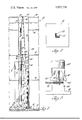
- FIG. 1 is a partial sectional view of a building including a shaft in which a pipe column is being fabricated DESCRIPITION OF THEPREFERRED EMBODIMENT
- the ground floor 12 of the building 10 rests directly on the earth 14.
- the building 10 includes several floors 16 between the ground floor 12 and the roof l8.
- the building 10 also includes a shaft 20 which houses a cluster of verticalpipe columns generally designated 22. I f
- Each of the pipe columns 22 is made up of several pipe sections from the availablesupply of pipe sections, generally designated 24, within the shaft 20.
- respective pipe sections 24 are consecutively appended to a suspended expanse of pipe, illustrated in FIG. as a suspendedexpanse of pipe 26.
- the expanse of pipe 26 is a single pipe section when the fabrication of a given pipe column 22 is first commenced, I
- the winch 30 is secured to a side wall 36 of the shaft 20, for example by means of mounting screws or bolts. It is understood and appreciated that the winch 30 could be rigidly positioned by diverse other means within the skill of the art.
- the pulley 32 includes a hook 38 which connects to a hook 40 carried by a support plate 42.
- the support plate 42 spans the shaft 20, and is supported by the roof 18 in the preferred embodi- 'ment. It is understood and appreciated that the support 3 plate 42 could be replaced by diverse other devices within the skill of the art, that the support plate 42 itself can take a variety of forms, and that it can be supportd at a floor 16 rather than at the roof 18.
- a second cable 44 extending from a second winch 46 and passing over a second pulley 48, is attached by a harness or collar 50 to the particular pipe section 24 which is to be joined to the expanse of pipe 26.
- the winch 46 like the winch 30, is secured to the side wall 36. Of course, it too could be positioned by other means.
- the pulley 48 includes a hook 52 which connects to a hook 54-connected to a support plate 56, which is similar to the support described for the pulley 32.
- the support plate 56 spans the shaft 20, and it is supported by a floor 16 in the preferred embodiment.
- support plate 42 numerous alternatives to the support plate 56 as described are available within the skill of the art.
- the pipe section 24' is supported at its lower end by a rotatable support member generally designated 58 placed on the ground floor 12.
- the rotatable support member 58 comprises a conical support member generally designated 60 comprising four truncated triangular plates 62, a bearing 64, and a base 66.
- a motor 68 As shown in FIG. l, a motor 68,
- the conical support member 60 which is inserted into the bottom of the pipe section '24, is effective to align the pipe section 24' for welding to the expanse of pipe 26.
- the triangular plates 62 permit use of a single support member 60 with a wide range of pipe diameters.
- the winches 30 and 46, and the motor 68, are con trolled from a control panel 74 which is located convenient to the operator.
- the attachment of the collar 50 to the pipe section 24' is illustrated by a phantom line representation of the pipe section 24', the cable 44, and the collar 50, as well as by the solid line representation of the pipe section 24, the cable 44, and the collar 50.
- the winch 46 is activated to lift the pipe section 24 from the ground floor 12.
- the pipe section 24' is then swung to the position where it rests on the support member 60 as shown.
- the expanse of pipe 26 is vertically raised by activating the winch 30.
- the expanse of pipe 26 is raised to a level so that its lower end is above the position of the upper end shown for the pipe section 24.
- the expanse of pipe 26 is lowered into abutting contact with the pipe section 24.
- the pipe section 24' is joined, in the preferred embodiment, to the expanse of pipe 26 by welding, such as by means of a torch 76. It is understood and appreciated that various alternative joining methods are possible within the skill of the art.
- the control panel 74' is caused to energize the motor 68 to rotate the conical support member 60.
- the pipe section 24 and the expanse of pipe 26 also rotate to per mit the weld to be made entirely around the circumference of the pipe.
- the winch 30 is activted to lift the expanse of pipe 26, with the pipe member 24' welded thereto, above the vertical height of a single pipe section 24.
- the collar 50 is then removed'from the bottom of this extended expanse of pipe 26 and attached to the next pipe section 24 to be added. The entire process is repeated as many times as required to produce a pipe column22 of the desired height.
- a pipe handling apparatus as in claim 1, wherein said means for rotating includes a rotatable conical support member.
- a pipe handling apparatus as in claim 1, wherein said means for suspending the second pipe section includes a winch and a cable.
- a pipe handling apparatus as in claim 3, wherein said means for suspending the second pipe section includes a pulley and a collar adapted to secure said cable to the second pipe section.
- a pipe handling apparatus as in claim 4, wherein said means for supporting the first pipe section includes means for suspending that pipe section.
- a pipe handling apparatus as in claim 5, wherein said means for suspending the first p'ipe section includes a winch, a cable, a pulley, and a collar suitable for attaching the cable to the first pipe section.
- a pipe handling apparatus as in claim 7, wherein said pipe sections are joined by welding, and wherein said first named winch, said second named winch, and said conical support member are power operated and are adapted to be controlled at a control panel adapted to be located proximate to the position of the apparatus operator.
Landscapes
- Physics & Mathematics (AREA)
- Optics & Photonics (AREA)
- Engineering & Computer Science (AREA)
- Mechanical Engineering (AREA)
- Conveying And Assembling Of Building Elements In Situ (AREA)
Abstract
A cable, extending from a winch and passing over a pulley, is attached to a pipe section supported at its lower end by a rotatable conical support member. The rotatable conical support member is rotated by a motor drive. A second cable, extending from a second winch and passing over a second pulley, is connected to an expanse of pipe, comprising one or more pipe sections, suspended vertically above the pipe section. The expanse of pipe and the pipe section are aligned so that the bottom of the expanse of pipe abuts the top of the pipe section. A welder-operator welds the pipe section to the expanse of pipe at the abutment, actuating the motor drive to rotate the conical support member and the pipe section to expose the entire circumference of the abutment. After the weld is complete, the winch coupled to the expanse of pipe is activated to raise the expanse of pipe. The next pipe section to be added to the expanse of pipe is then attached to the other cable. That pipe section is then placed on the conical support member, and the process is repeated.
Description
[ Dec. 23, 1975 United States Patent 1191 Rekawek APPARATUS TO FACILITATE JOINING PIPE SECTIONS TOGETHER TO FORM A Primary Examiner-Carl E. Hall Attorney, Agent, or Firm-Reising, Ethington, Barnard, Perry and Brooks VERTICAL PIPE COLUMN [75] Inventor: Janusz J. Rekawek, Clarkston,
Mich- [57] ABSTRACT [73] Assigneez Dare] Bennett, Royal Oak, Mich A cable extending from a winch and passing over a D pulley, is attached to a pipe sect1on supported at 1ts Flledi P 1974 lower end by a rotatable conical support member. The [21] Appl' NO; 462,843 rotatable conical support member is rotated by a motor dr1ve. A second cable, extending from a second winch and passing over a second pulley, is connected [52] US. Cl 214/1 P; 29/200 P; 52/123; to an expanse of pipe, comprising one or more pipe 269/45 sections, suspended vertically above the pipe section. [51] Int. Cl. B23K 37/04 The x an e of pipe and the pipe section are aligned Field of Searchi so that the bottom of the expanse of pipe abuts the top 200 1 of the pipe section. A welder-operator welds the pipe 173 R, 183 section to the expanse of pipe at the abutment, actuating the motor drive to rotate the conical support mem- [56] References Clted ber and the pipe section to expose the entire circum- UNTTED STATES PATENTS ference of the abutment. After the weld is complete, 1,605,472 11/1926 Schick 52/123 the coupled expanse of P is activated 1,906,362 5/1933 214/])[(; 3 to ra1se the expanse of pipe. The next pipe section to 2,463,907 3 1949 Risley et a1. 228/48 be added to the expanse of i e is then attached to the 3,494,593 2/1970 Blagg 254/139 other cable. That pipe section is then placed on the 3,497,787 2/ 1970 Fuelster et al. 254/173 R ical support member, and the process is repeated. 3,657,786 4/1972 Wiswell, Jr. 29/200 P 8 Claims, 3 Drawing Figures 44 4 x0 3 L 3% p 1 i be a 28 I if 4" f E 76 i I q l l 1 41/ it E I 3 5 g 21 5 a1 1 l j i I a (46K krsag @131 14" US. Patent Dec. 23, 1975 3,927,770
7g Willi 6% APPARATUS TO FACILITATE JOINING PIPE SECTIONS TOGETHER TO FORM A VERTICAL PIPE COLUMN FIELD OF THE INVENTION This invention relates to amethod and apparatus to facilitate joining pipe sections together to form a vertical pipe column. I
DESCRIPTION OFTHE PRIOR ART It is commonplace to provide a shaft in a building to house a cluster of pipe columns extending from the ground level of the building to the top of the building. These pipe columns are fabricated by joining several pipe sections together. Typically, thesepipe columns are assembled from the ground up. For example, a welder may progress up through the floors of the. building welding additional pipe sections to the tops of the growing pipe columns. Using this method, equipment and pipe sections must be transported from floor to floor as the pipe columns increase in height. In view of the need to move equipment and supplies, it should be readily appreciated that this conventional approach to the fabrication of pipe columns is a slow and cumbersome process. I
The known prior art pertinent to the fabrication of pipe columns offers no guidance as to possible improvements in this slow and cumbersome process. Patents directed to the assembly of well casings are illustrative of the prior art--for example, US. Pat. Nos. Baker 2,956,l47 and Thornburg 2,972,388. Each of these patents discloses an approach to fabricating pipe columns similar to that described above: Pipe sections are consecutively added to the top of a growing vertical pipe column.
Prior art welding mechanisms are no more helpful than the casing patents noted. Representative welding mechanisms are disclosed in two patents toPatterson US. Pat. No. 2,440,696 and 2,440,697. Nor is any valuable insight available from the general construction arts. Methods and apparatus for assembling storage enclosures are described in the US. Pat. Nos. to Raymond 1,872,810 and Talcott-2,708,012. TheRaymond patent discloses an assembly approach involving the addition of sections to the top of a growing metal assembly. Talcott discloses the construction of additional sections beneath completed sections, but it provides nothing of value in respect of the problems confronted in the assembly of pipe columns in buildings.
SUMMARY OF THE INVENTION out from a single position. The instant method and apparatus present advancements altogether unknown in the prior art. V
A cable, extending from a winch and passing over a pulley, is attached to a pipe section supported at its lower end by a rotatable conical support memberi The rotatable conical support member is rotated by a motor drive. A second cable, extending from a second winch 'and passing over a second pulley, is connected to an expanse of pipe, eomprising one or more pipe sections, suspended vertically above the pipe section. The expanse of pipe and the pipe section are aligned so that the bottom of the expanse of 2 pipe abuts the top of the pipe section. A welder-operator welds the pipe section to the expanse of pipe at the abutment, actuating the motor drive to rotate the conical support-member and the pipe section to expose the entire circumference of the abutment. After the weld is complete, the winch coupled to the expanse of pipe is activated to raise the expanse of pipe. The next pipe section to be added to theexpanse of pipe is then attached to the other cable. That pipe section is then placed on the conical support member, and the process is repeated.
BRIEF DESCRIPTION OF THE DRAWINGS i The instant invention can be best understood by reference to the following description of a preferred embodiment taken in connection with the accompanying drawings,,in which:
FIG. 1 is a partial sectional view of a building including a shaft in which a pipe column is being fabricated DESCRIPITION OF THEPREFERRED EMBODIMENT Reference should now be made to the drawings and more particularly to FIG. 1 wherein the apparatus of the present invention is illustrated as it is used in a building generally designated 10. The ground floor 12 of the building 10 rests directly on the earth 14. The building 10 includes several floors 16 between the ground floor 12 and the roof l8. As best illustrated in FIG. 2, the building 10 also includes a shaft 20 which houses a cluster of verticalpipe columns generally designated 22. I f
Each of the pipe columns 22 is made up of several pipe sections from the availablesupply of pipe sections, generally designated 24, within the shaft 20. Using the instant method and apparatus to fabricate a pipe column 22, respective pipe sections 24 are consecutively appended to a suspended expanse of pipe, illustrated in FIG. as a suspendedexpanse of pipe 26. A cable 28, extending from a winch 30 and passing over a pulley 32, is attached by a harness or collar 34 to the expanse of pipe 26 to suspend the expanse of pipe 26 at a controllable elevation above the ground floor 12. The expanse of pipe 26 is a single pipe section when the fabrication of a given pipe column 22 is first commenced, I
and it increases in length each time an additional pipe section is joined to the lower end of the expanse 26.
The winch 30 is secured to a side wall 36 of the shaft 20, for example by means of mounting screws or bolts. It is understood and appreciated that the winch 30 could be rigidly positioned by diverse other means within the skill of the art. The pulley 32 includes a hook 38 which connects to a hook 40 carried by a support plate 42. The support plate 42 spans the shaft 20, and is supported by the roof 18 in the preferred embodi- 'ment. It is understood and appreciated that the support 3 plate 42 could be replaced by diverse other devices within the skill of the art, that the support plate 42 itself can take a variety of forms, and that it can be supportd at a floor 16 rather than at the roof 18.
A second cable 44, extending from a second winch 46 and passing over a second pulley 48, is attached by a harness or collar 50 to the particular pipe section 24 which is to be joined to the expanse of pipe 26. The winch 46, like the winch 30, is secured to the side wall 36. Of course, it too could be positioned by other means. The pulley 48 includes a hook 52 which connects to a hook 54-connected to a support plate 56, which is similar to the support described for the pulley 32. The support plate 56 spans the shaft 20, and it is supported by a floor 16 in the preferred embodiment.
, As for the support plate 42, numerous alternatives to the support plate 56 as described are available within the skill of the art.
The pipe section 24' is supported at its lower end by a rotatable support member generally designated 58 placed on the ground floor 12. As best illustrated in FIG. 3, the rotatable support member 58 comprises a conical support member generally designated 60 comprising four truncated triangular plates 62, a bearing 64, and a base 66. As shown in FIG. l, a motor 68,
coupled to a drive mechanism 70, drives the conical support member 60 in a conventional manner through a chain or belt 72. It is understood and apppreciated that alternative drive arrangements could be substituted for the motor 68, the drive mechanism 70, and the chain or belt 72 r The conical support member 60, which is inserted into the bottom of the pipe section '24, is effective to align the pipe section 24' for welding to the expanse of pipe 26. The triangular plates 62 permit use of a single support member 60 with a wide range of pipe diameters.
The winches 30 and 46, and the motor 68, are con trolled from a control panel 74 which is located convenient to the operator.
When a pipe section 24 is to be added to the expanse of pipe 26, the collar 50 is attached to that pipe section. The following example is-directed to the pipe section 24.
The attachment of the collar 50 to the pipe section 24' is illustrated by a phantom line representation of the pipe section 24', the cable 44, and the collar 50, as well as by the solid line representation of the pipe section 24, the cable 44, and the collar 50. After the collar 50 is attached to the pipe section 24' as shown in phantom, the winch 46 is activated to lift the pipe section 24 from the ground floor 12. The pipe section 24' is then swung to the position where it rests on the support member 60 as shown.
Before the pipe section 24 is swung to the position illustrated in solid line, the expanse of pipe 26 is vertically raised by activating the winch 30. The expanse of pipe 26 is raised to a level so that its lower end is above the position of the upper end shown for the pipe section 24. After the pipe section 24 is positioned as shown, the expanse of pipe 26 is lowered into abutting contact with the pipe section 24.
The pipe section 24' is joined, in the preferred embodiment, to the expanse of pipe 26 by welding, such as by means of a torch 76. It is understood and appreciated that various alternative joining methods are possible within the skill of the art. During the welding operation, the control panel 74'is caused to energize the motor 68 to rotate the conical support member 60. As the conical support member rotates, the pipe section 24 and the expanse of pipe 26 also rotate to per mit the weld to be made entirely around the circumference of the pipe. After the weld is complete, the winch 30 is activted to lift the expanse of pipe 26, with the pipe member 24' welded thereto, above the vertical height of a single pipe section 24. The collar 50 is then removed'from the bottom of this extended expanse of pipe 26 and attached to the next pipe section 24 to be added. The entire process is repeated as many times as required to produce a pipe column22 of the desired height.
Although theforegoing has proceeded in terms of a particular preferred embodiment, it is understood and appreciated that various changes and modifications could be engrafted thereon by one skilled in the art within the spirit and scope of the appended claims.
The embodiments of the invention in which an exclusive property or privilege is claimed are defined as follows:
l. A pipe handling apparatus comprising:
means for supporting a first pipe section in a substantially vertical orientation; means for suspending a second pipe section at a vertical height above the first pipe section, the second pipe section being suspended in a substantially vertical orientation; I
means for controlling the relative positions of the first pipe section and the second pipe section such that the pipe sections are abutted end to end while in the vertical orientation and can be joined together; and
means for rotating the first pipe section and the second pipe section about a substantially vertical axis while the second pipe section is a'butted to the first pipe section. a
2. A pipe handling apparatus as in claim 1, wherein said means for rotating includes a rotatable conical support member.
3. A pipe handling apparatus as in claim 1, wherein said means for suspending the second pipe section includes a winch and a cable.
4. A pipe handling apparatus as in claim 3, wherein said means for suspending the second pipe section includes a pulley and a collar adapted to secure said cable to the second pipe section.
5. A pipe handling apparatus as in claim 4, wherein said means for supporting the first pipe section includes means for suspending that pipe section.
6. A pipe handling apparatus as in claim 5, wherein said means for suspending the first p'ipe section includes a winch, a cable, a pulley, and a collar suitable for attaching the cable to the first pipe section.
7. A pipe handling apparatus as in claim 6, including a conical support member adapted to support the first pipe section and to align the first pipe section with the second pipe section.
8. A pipe handling apparatus as in claim 7, wherein said pipe sections are joined by welding, and wherein said first named winch, said second named winch, and said conical support member are power operated and are adapted to be controlled at a control panel adapted to be located proximate to the position of the apparatus operator.
Claims (8)
1. A pipe handling apparatus comprising: means for supporting a first pipe section in a substantially vertical orientation; means for suspending a second pipe section at a vertical height above the first pipe section, the second pipe section being suspended in a substantially vertical orientation; means for controlling the relative positions of the first pipe section and the second pipe section such that the pipe sections are abutted end to end while in the vertical orientation and can be joined together; and means for rotating the first pipe section and the second pipe section about a substantially vertical axis while the second pipe section is abutted to the first pipe section.
2. A pipe handling apparatus as in claim 1, wherein said means for rotating includes a rotatable conical support member.
3. A pipe handling apparatus as in claim 1, wherein said means for suspending the second pipe section includes a winch and a cable.
4. A pipe handling apparatus as in claim 3, wherein said means for suspending the second pipe section includes a pulley and a collar adapted to secure said cable to the second pipe section.
5. A pipe handling apparatus as in claim 4, wherein said means for supporting the first pipe section includes means for suspending that pipe section.
6. A pipe handling apparatus as in claim 5, wherein said means for suspending the first pipe section includes a winch, a cable, a pulley, and a collar suitable for attaching the cable to the first pipe section.
7. A pipe handling apparatus as in claim 6, including a conical support member adapted to support the first pipe section and to align the first pipe section with the second pipe section.
8. A pipe handling apparatus as in claim 7, wherein said pipe sections are joined by welding, and wherein said first named winch, said second named winch, and said conical support member are power operated and are adapted to be controlled at a control panel adapted to be located proximate to the position of the apparatus operator.
Priority Applications (1)
| Application Number | Priority Date | Filing Date | Title |
|---|---|---|---|
| US462843A US3927770A (en) | 1974-04-22 | 1974-04-22 | Apparatus to facilitate joining pipe sections together to form a vertical pipe column |
Applications Claiming Priority (1)
| Application Number | Priority Date | Filing Date | Title |
|---|---|---|---|
| US462843A US3927770A (en) | 1974-04-22 | 1974-04-22 | Apparatus to facilitate joining pipe sections together to form a vertical pipe column |
Publications (1)
| Publication Number | Publication Date |
|---|---|
| US3927770A true US3927770A (en) | 1975-12-23 |
Family
ID=23837983
Family Applications (1)
| Application Number | Title | Priority Date | Filing Date |
|---|---|---|---|
| US462843A Expired - Lifetime US3927770A (en) | 1974-04-22 | 1974-04-22 | Apparatus to facilitate joining pipe sections together to form a vertical pipe column |
Country Status (1)
| Country | Link |
|---|---|
| US (1) | US3927770A (en) |
Cited By (6)
| Publication number | Priority date | Publication date | Assignee | Title |
|---|---|---|---|---|
| US4111374A (en) * | 1975-02-05 | 1978-09-05 | Mackaness James B | Commodity conveying means |
| US4197975A (en) * | 1977-10-14 | 1980-04-15 | Mather & Platt Limited | Pool brazing apparatus for manufacturing rotor cages |
| US20070107366A1 (en) * | 2005-10-14 | 2007-05-17 | Enrique Franco | Apparatus and method for manufacturing poles and columns |
| CN102773619A (en) * | 2012-07-02 | 2012-11-14 | 林德工程(杭州)有限公司 | Vertical type assembly welding method for space division aluminum tower |
| CN103567601A (en) * | 2013-11-12 | 2014-02-12 | 中国化学工程第三建设有限公司 | Method for welding tower in vertical assembling mode by utilizing jacks and crane |
| CN110900021A (en) * | 2019-11-28 | 2020-03-24 | 中国化学工程第三建设有限公司 | Reactor assembly welding method in narrow space of dehydrogenation device frame |
Citations (6)
| Publication number | Priority date | Publication date | Assignee | Title |
|---|---|---|---|---|
| US1605472A (en) * | 1923-06-16 | 1926-11-02 | Fredrick W Schick | Hoisting device |
| US1906362A (en) * | 1931-03-11 | 1933-05-02 | Harnischfeger Corp | Pipe handling machine |
| US2463907A (en) * | 1944-11-23 | 1949-03-08 | Dresser Ind | Method and apparatus for welding pipe |
| US3494593A (en) * | 1968-01-29 | 1970-02-10 | Schlumberger Technology Corp | Portable mast |
| US3497787A (en) * | 1967-02-03 | 1970-02-24 | Nordberg Manufacturing Co | Mine hoist control system |
| US3657786A (en) * | 1970-03-11 | 1972-04-25 | George C Wiswell Jr | Laying of subaqueous pipe |
-
1974
- 1974-04-22 US US462843A patent/US3927770A/en not_active Expired - Lifetime
Patent Citations (6)
| Publication number | Priority date | Publication date | Assignee | Title |
|---|---|---|---|---|
| US1605472A (en) * | 1923-06-16 | 1926-11-02 | Fredrick W Schick | Hoisting device |
| US1906362A (en) * | 1931-03-11 | 1933-05-02 | Harnischfeger Corp | Pipe handling machine |
| US2463907A (en) * | 1944-11-23 | 1949-03-08 | Dresser Ind | Method and apparatus for welding pipe |
| US3497787A (en) * | 1967-02-03 | 1970-02-24 | Nordberg Manufacturing Co | Mine hoist control system |
| US3494593A (en) * | 1968-01-29 | 1970-02-10 | Schlumberger Technology Corp | Portable mast |
| US3657786A (en) * | 1970-03-11 | 1972-04-25 | George C Wiswell Jr | Laying of subaqueous pipe |
Cited By (9)
| Publication number | Priority date | Publication date | Assignee | Title |
|---|---|---|---|---|
| US4111374A (en) * | 1975-02-05 | 1978-09-05 | Mackaness James B | Commodity conveying means |
| US4197975A (en) * | 1977-10-14 | 1980-04-15 | Mather & Platt Limited | Pool brazing apparatus for manufacturing rotor cages |
| US20070107366A1 (en) * | 2005-10-14 | 2007-05-17 | Enrique Franco | Apparatus and method for manufacturing poles and columns |
| US7926694B2 (en) * | 2005-10-14 | 2011-04-19 | Enrique Franco | Apparatus for vertically manufacturing poles and columns |
| CN102773619A (en) * | 2012-07-02 | 2012-11-14 | 林德工程(杭州)有限公司 | Vertical type assembly welding method for space division aluminum tower |
| CN102773619B (en) * | 2012-07-02 | 2016-01-20 | 林德工程(杭州)有限公司 | The empty point vertical welding method of aluminium tower |
| CN103567601A (en) * | 2013-11-12 | 2014-02-12 | 中国化学工程第三建设有限公司 | Method for welding tower in vertical assembling mode by utilizing jacks and crane |
| CN103567601B (en) * | 2013-11-12 | 2015-12-09 | 中国化学工程第三建设有限公司 | Utilize jack welding tower vertical with crane method |
| CN110900021A (en) * | 2019-11-28 | 2020-03-24 | 中国化学工程第三建设有限公司 | Reactor assembly welding method in narrow space of dehydrogenation device frame |
Similar Documents
| Publication | Publication Date | Title |
|---|---|---|
| US3927770A (en) | Apparatus to facilitate joining pipe sections together to form a vertical pipe column | |
| KR102817215B1 (en) | Horizontal rotary vertical welding device | |
| JPS6119955B2 (en) | ||
| US3464520A (en) | Self-operated elevator | |
| US3935987A (en) | Method for rotation of plates to facilitate weldment | |
| JP3083082B2 (en) | Method and apparatus for manufacturing beam-piercing type steel column | |
| JPH06123794A (en) | Remote furnace working device and working method thereof | |
| JPS62117953A (en) | Muliwork robot | |
| JPH0422478B2 (en) | ||
| KR101444603B1 (en) | Pile welding equipment | |
| KR960007325B1 (en) | Welding unit and welding device | |
| JPH07895B2 (en) | Reinforcing cage construction equipment | |
| JP2831253B2 (en) | Automatic welding method for inner surface reinforcement of cylindrical shells | |
| JPH09248695A (en) | Automatic welding equipment for ring seam of funnel cylinder | |
| JPS6072680A (en) | Method and device for welding tower-like structure | |
| JP7236401B2 (en) | Lifting jig for removing and transferring gas turbine combustor and method for removing and transferring. | |
| CN206854924U (en) | A kind of flange slab overturning machine | |
| JP3049406B2 (en) | Handling device and building method using the same | |
| KR101630433B1 (en) | Pile welding equipment | |
| JP4741403B2 (en) | Gondola device for gas holder, access method to gas holder side wall | |
| JP2004004001A (en) | Equipment and method for performing maintenance in plant area partitioned by such a wall having surfaces with at least 2 opposite surfaces | |
| JPS60188895A (en) | Vertical pump maintenance equipment | |
| CN217650859U (en) | A storage tank auxiliary tooling | |
| JPH06322992A (en) | Wall erection device | |
| CN117961385B (en) | Pipeline pipe bracket installation welding device suitable for heat supply pipeline in chemical industry place |