US3905472A - Conveying apparatus for heat treatment furnaces - Google Patents
Conveying apparatus for heat treatment furnaces Download PDFInfo
- Publication number
- US3905472A US3905472A US417598A US41759873A US3905472A US 3905472 A US3905472 A US 3905472A US 417598 A US417598 A US 417598A US 41759873 A US41759873 A US 41759873A US 3905472 A US3905472 A US 3905472A
- Authority
- US
- United States
- Prior art keywords
- rollers
- rotation
- conveying apparatus
- axes
- conveying
- Prior art date
- Legal status (The legal status is an assumption and is not a legal conclusion. Google has not performed a legal analysis and makes no representation as to the accuracy of the status listed.)
- Expired - Lifetime
Links
Images

Classifications
-
- F—MECHANICAL ENGINEERING; LIGHTING; HEATING; WEAPONS; BLASTING
- F27—FURNACES; KILNS; OVENS; RETORTS
- F27B—FURNACES, KILNS, OVENS OR RETORTS IN GENERAL; OPEN SINTERING OR LIKE APPARATUS
- F27B9/00—Furnaces through which the charge is moved mechanically, e.g. of tunnel type; Similar furnaces in which the charge moves by gravity
- F27B9/14—Furnaces through which the charge is moved mechanically, e.g. of tunnel type; Similar furnaces in which the charge moves by gravity characterised by the path of the charge during treatment; characterised by the means by which the charge is moved during treatment
- F27B9/20—Furnaces through which the charge is moved mechanically, e.g. of tunnel type; Similar furnaces in which the charge moves by gravity characterised by the path of the charge during treatment; characterised by the means by which the charge is moved during treatment the charge moving in a substantially straight path
- F27B9/26—Furnaces through which the charge is moved mechanically, e.g. of tunnel type; Similar furnaces in which the charge moves by gravity characterised by the path of the charge during treatment; characterised by the means by which the charge is moved during treatment the charge moving in a substantially straight path on or in trucks, sleds, or containers
-
- B—PERFORMING OPERATIONS; TRANSPORTING
- B65—CONVEYING; PACKING; STORING; HANDLING THIN OR FILAMENTARY MATERIAL
- B65G—TRANSPORT OR STORAGE DEVICES, e.g. CONVEYORS FOR LOADING OR TIPPING, SHOP CONVEYOR SYSTEMS OR PNEUMATIC TUBE CONVEYORS
- B65G23/00—Driving gear for endless conveyors; Belt- or chain-tensioning arrangements
- B65G23/02—Belt- or chain-engaging elements
-
- F—MECHANICAL ENGINEERING; LIGHTING; HEATING; WEAPONS; BLASTING
- F27—FURNACES; KILNS; OVENS; RETORTS
- F27B—FURNACES, KILNS, OVENS OR RETORTS IN GENERAL; OPEN SINTERING OR LIKE APPARATUS
- F27B9/00—Furnaces through which the charge is moved mechanically, e.g. of tunnel type; Similar furnaces in which the charge moves by gravity
- F27B9/14—Furnaces through which the charge is moved mechanically, e.g. of tunnel type; Similar furnaces in which the charge moves by gravity characterised by the path of the charge during treatment; characterised by the means by which the charge is moved during treatment
- F27B9/20—Furnaces through which the charge is moved mechanically, e.g. of tunnel type; Similar furnaces in which the charge moves by gravity characterised by the path of the charge during treatment; characterised by the means by which the charge is moved during treatment the charge moving in a substantially straight path
- F27B9/24—Furnaces through which the charge is moved mechanically, e.g. of tunnel type; Similar furnaces in which the charge moves by gravity characterised by the path of the charge during treatment; characterised by the means by which the charge is moved during treatment the charge moving in a substantially straight path being carried by a conveyor
- F27B9/2407—Furnaces through which the charge is moved mechanically, e.g. of tunnel type; Similar furnaces in which the charge moves by gravity characterised by the path of the charge during treatment; characterised by the means by which the charge is moved during treatment the charge moving in a substantially straight path being carried by a conveyor the conveyor being constituted by rollers (roller hearth furnace)
-
- F—MECHANICAL ENGINEERING; LIGHTING; HEATING; WEAPONS; BLASTING
- F27—FURNACES; KILNS; OVENS; RETORTS
- F27B—FURNACES, KILNS, OVENS OR RETORTS IN GENERAL; OPEN SINTERING OR LIKE APPARATUS
- F27B9/00—Furnaces through which the charge is moved mechanically, e.g. of tunnel type; Similar furnaces in which the charge moves by gravity
- F27B9/14—Furnaces through which the charge is moved mechanically, e.g. of tunnel type; Similar furnaces in which the charge moves by gravity characterised by the path of the charge during treatment; characterised by the means by which the charge is moved during treatment
- F27B9/20—Furnaces through which the charge is moved mechanically, e.g. of tunnel type; Similar furnaces in which the charge moves by gravity characterised by the path of the charge during treatment; characterised by the means by which the charge is moved during treatment the charge moving in a substantially straight path
- F27B9/24—Furnaces through which the charge is moved mechanically, e.g. of tunnel type; Similar furnaces in which the charge moves by gravity characterised by the path of the charge during treatment; characterised by the means by which the charge is moved during treatment the charge moving in a substantially straight path being carried by a conveyor
- F27B9/243—Endless-strand conveyor
-
- F—MECHANICAL ENGINEERING; LIGHTING; HEATING; WEAPONS; BLASTING
- F27—FURNACES; KILNS; OVENS; RETORTS
- F27D—DETAILS OR ACCESSORIES OF FURNACES, KILNS, OVENS OR RETORTS, IN SO FAR AS THEY ARE OF KINDS OCCURRING IN MORE THAN ONE KIND OF FURNACE
- F27D3/00—Charging; Discharging; Manipulation of charge
- F27D2003/0034—Means for moving, conveying, transporting the charge in the furnace or in the charging facilities
- F27D2003/0067—Means for moving, conveying, transporting the charge in the furnace or in the charging facilities comprising conveyors where the translation is communicated by friction from at least one rotating element, e.g. two opposed rotations combined
-
- F—MECHANICAL ENGINEERING; LIGHTING; HEATING; WEAPONS; BLASTING
- F27—FURNACES; KILNS; OVENS; RETORTS
- F27M—INDEXING SCHEME RELATING TO ASPECTS OF THE CHARGES OR FURNACES, KILNS, OVENS OR RETORTS
- F27M2001/00—Composition, conformation or state of the charge
- F27M2001/16—Particulate material, e.g. comminuted scrap
Definitions
- ABSTRACT There is provided a conveying apparatus for the transport of conveyor belts, straps made of wire links, or conveying boxes in a heat treatment furnace in which the driving force to the articles conveyed takes place through two or more rolls rotating at the same speed in opposite directions, the rolls lie in a horizontal plane, are arranged in an acute angle to the conveying direction and forms an acute angle with each other.
- This invention relates to conveying apparatus for heat treatment furnaces in the case of which the material that is to be treated is transported by means of conveyor belts, straps made of wire links or conveying boxes.
- the present invention makes it possible to avoid the main disadvantage of the known conveying apparatuses, namely the high mechanical stress on the conveying belts or boxes.
- This object is achieved by the fact that the propelling force is made uniformly effective along the entire furnace and does not, as in the case of the conveyor belt, only act locally by the driving roll or in the case of pushing through furnaces by locally concentrated pushing.
- the problem on which the invention is based is to distribute the driving force uniformly over the conveying path and the objects or articles to be conveyed, such as conveyor belts, straps of wire links, boxes, shuttles, plates or jointed bands subdivided into individual boxes.
- this problem is solved by imparting the driving force to the articles that are to be conveyed by two or more rolls disposed with their longitudinal axes at an acute angle in relation to the direcvlion of transportation, which rolls move at the same speed of rotation, but in an opposite rotational direction.
- the rolls can be developed solid or hollow and they have their longitudinal axes slightly inclined in the direction of conveyance. However, the longitudinal axes of the rolls always lie in one plane.
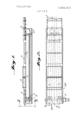
- FIG. 1 is a longitudinal sectional view of one form of apparatus accordingto the invention taken along the line l- 1 of FIG. 2;
- FIG. 2 is a top plan view of the apparatus of FIG. 1;
- FIG. 3 is afrontview along the line 33 of FIG. 1;
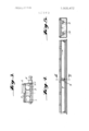
- FIG. 4 is a view showing how the bearing is eccentric to the. rolls; f
- FIG. 5 is a sectional view along the line 55 of FIG.
- FIG. 6 is a sectional view of another form of the invention taken along the line 6-6 of FIG. 7;
- FIG. 7 is a top plan view of the apparatus of FIG. 6.
- FIGS. 1, 2 and 3 they illustrate the basic idea of the invention.
- the core of the invention are the two rolls or tubes 1 and 20 in the furnace indicated generically at 25.
- the rolls extend in the direction of transportation. In the following description they are referred to merely as rolls.
- the rolls 1 and 20 resting in the bearings 2 and 22 run somewhat transversely in relation to the direction of transportation and as a result of that together form an acute angle'in the range of magnitude of 1 to 15. In the embodiment shown in FIG. 2, the acute angle is approximately 4 /2.
- the rolls 1 and 20 are put into rotation by way of oppositely pitched worm gears 3 driven in the same direction by a motor 4, whereby the rotational direction of the rolls 1 and 20 are in opposing directions, the number of revolutions for both' however is the same.
- the driving force can also be accomplished in some other manner, thus for example, by means of chains or V-belts, etc.
- the article to be conveyed as shown in FIG. 1 can be a conveyor belt 5 loaded with bulk material; however, boxes 6, plates 7 or a band 8 of wire links subdivided into individual boxes can also be conveyed. From this basic embodiment of the conveying device, various modifications can be deduced, which have advantages for special cases of application.
- journal pins 9 are made eccentrically in relation to the rolls 1.
- the article that is to be conveyed is periodically lifted at a rotational angle from a stationary support, conveyed in the direction of conveyance and then released on the stationary support until discharged.
- the type of conveyance in this case corresponds to that of a walking beam assembly whereby, however, the driving is accomplished only by rotation of the rolls, whereas in the case of the walking beam assembly, the hoisting and the forward movement of the beam requires two types of movements.
- FIGS. 6 and 7 show a different embodiment of the invention.
- the returning flight of an endless conveyor strap assembly is pressed from below against the rolls, as by the bight portion of a U-shaped trough structure 34.
- the conveying arrangement as shown in FIG. 6, can be mounted slightly inclined in the direction of conveyance.
- the conveyor belt is equipped with transverse strips 11 and the rolls with pins, such as pins 10, 24, 26, 28, and 32,'as is shown by way of example in FIGS. 6 and 7, then one will achieve a positive conveyance of the belt.
- Conveying apparatus for conveyance of conveyor belts, wire link straps, conveyor boxes or the like in a heat treatment furnace, comprising a pair of similar cylindrical rollers defining a single conveying path, means mounting said rollers in generally longitudinally coextensive relation for rotation about axes disposed within a generally horizontal plane in converging relationship with respect to one another in the direction of the conveying path at an acute angle in the range of magnitude of 1 to 15, the axes of rotation of each roller being coexistent with the axis of the cylindrical form thereof, means for simultaneously rotating said rollers about their axes of rotation in opposite directions so that their upper peripheries move with lateral components of movement which are equal and in opposite directions and longitudinal components of movement which are both in the Harborrection, and both of endless flexible means encircling both of said rollers including an upper flight engaging the upper periphery of said rollers and a return flight below said rollers and means for pressing said return flight upwardly against the lower periphery of said rollers.
- Conveying apparatus as defined in claim 1 wherein said endless flexible means includes a plurality of parallel transverse straps facing said rollers and a plurality of driving members extending outwardly from the periphery of said rollers for engaging said straps during the rotation of said rollers.
Landscapes
- Engineering & Computer Science (AREA)
- Mechanical Engineering (AREA)
- General Engineering & Computer Science (AREA)
- Structure Of Belt Conveyors (AREA)
- Tunnel Furnaces (AREA)
- Heat Treatments In General, Especially Conveying And Cooling (AREA)
- Belt Conveyors (AREA)
Priority Applications (1)
| Application Number | Priority Date | Filing Date | Title |
|---|---|---|---|
| US05/609,156 US3998323A (en) | 1972-12-04 | 1975-08-29 | Conveying apparatus for heat treatment furnaces |
Applications Claiming Priority (1)
| Application Number | Priority Date | Filing Date | Title |
|---|---|---|---|
| DE2259300A DE2259300C2 (de) | 1972-12-04 | 1972-12-04 | Fördervorrichtung zum Transport von Förderbändern, Drahtgliedergurten oder Förderkästen in einem Wärmebehandlungsofen |
Related Child Applications (1)
| Application Number | Title | Priority Date | Filing Date |
|---|---|---|---|
| US05/609,156 Continuation US3998323A (en) | 1972-12-04 | 1975-08-29 | Conveying apparatus for heat treatment furnaces |
Publications (1)
| Publication Number | Publication Date |
|---|---|
| US3905472A true US3905472A (en) | 1975-09-16 |
Family
ID=5863462
Family Applications (1)
| Application Number | Title | Priority Date | Filing Date |
|---|---|---|---|
| US417598A Expired - Lifetime US3905472A (en) | 1972-12-04 | 1973-11-20 | Conveying apparatus for heat treatment furnaces |
Country Status (7)
| Country | Link |
|---|---|
| US (1) | US3905472A (enExample) |
| JP (1) | JPS506075A (enExample) |
| CH (1) | CH560366A5 (enExample) |
| DE (1) | DE2259300C2 (enExample) |
| FR (1) | FR2212915A5 (enExample) |
| GB (1) | GB1424930A (enExample) |
| YU (1) | YU35738B (enExample) |
Cited By (7)
| Publication number | Priority date | Publication date | Assignee | Title |
|---|---|---|---|---|
| US3998323A (en) * | 1972-12-04 | 1976-12-21 | Deutsche Gold- Und Silber-Scheideanstalt Vormals Roessler | Conveying apparatus for heat treatment furnaces |
| US5135103A (en) * | 1987-06-26 | 1992-08-04 | Focke & Co. | Packaging machine, especially for cigarettes |
| US5499709A (en) * | 1994-04-15 | 1996-03-19 | Alvey, Inc. | Conveyor with separator/aligner |
| US5706929A (en) * | 1995-04-17 | 1998-01-13 | Alvey, Inc. | Conveyor with high speed case turner |
| US5997234A (en) * | 1997-04-29 | 1999-12-07 | Ebara Solar, Inc. | Silicon feed system |
| US20030209098A1 (en) * | 2002-05-07 | 2003-11-13 | Gilles Kalbermatten | Apparatus for orienting tablets |
| US9051122B2 (en) | 2012-11-30 | 2015-06-09 | Raymond Edward Poehlein | Idler roller conveyor system |
Families Citing this family (2)
| Publication number | Priority date | Publication date | Assignee | Title |
|---|---|---|---|---|
| DE2254795C3 (de) * | 1972-11-09 | 1982-01-28 | GEGA Gesellschaft für Gasetechnik Lotz KG, 6201 Wallau | Brennschneidmaschine |
| CA1304869C (en) * | 1986-10-21 | 1992-07-07 | Peter H. Markusch | Continuous process for the production of aqueous polyurethane-urea dispersions |
Citations (3)
| Publication number | Priority date | Publication date | Assignee | Title |
|---|---|---|---|---|
| US2602537A (en) * | 1949-11-15 | 1952-07-08 | United Eng Foundry Co | Gathering table |
| US2733801A (en) * | 1956-02-07 | Inclined | ||
| US3464131A (en) * | 1966-04-21 | 1969-09-02 | G A Braun | Combination spreader-feeder for flat work ironer |
Family Cites Families (2)
| Publication number | Priority date | Publication date | Assignee | Title |
|---|---|---|---|---|
| DE1297637B (de) * | 1966-07-06 | 1969-06-19 | Wilhelm Krause | Einrichtung zum Transportieren von metallischen Werkstuecken in Waermoefen oder auf Kuehlbetten |
| DE1783094C3 (de) * | 1966-10-12 | 1974-08-08 | Wilhelm 4300 Essen Krause | Einrichtung zum Transportieren metallischer Werkstücke in Wärmöfen. Ausscheidung aus: 1297637 |
-
1972
- 1972-12-04 DE DE2259300A patent/DE2259300C2/de not_active Expired
-
1973
- 1973-11-20 US US417598A patent/US3905472A/en not_active Expired - Lifetime
- 1973-12-03 CH CH1690173A patent/CH560366A5/xx not_active IP Right Cessation
- 1973-12-03 JP JP48135643A patent/JPS506075A/ja active Pending
- 1973-12-03 GB GB5597673A patent/GB1424930A/en not_active Expired
- 1973-12-04 YU YU3126/73A patent/YU35738B/xx unknown
- 1973-12-04 FR FR7343280A patent/FR2212915A5/fr not_active Expired
Patent Citations (3)
| Publication number | Priority date | Publication date | Assignee | Title |
|---|---|---|---|---|
| US2733801A (en) * | 1956-02-07 | Inclined | ||
| US2602537A (en) * | 1949-11-15 | 1952-07-08 | United Eng Foundry Co | Gathering table |
| US3464131A (en) * | 1966-04-21 | 1969-09-02 | G A Braun | Combination spreader-feeder for flat work ironer |
Cited By (8)
| Publication number | Priority date | Publication date | Assignee | Title |
|---|---|---|---|---|
| US3998323A (en) * | 1972-12-04 | 1976-12-21 | Deutsche Gold- Und Silber-Scheideanstalt Vormals Roessler | Conveying apparatus for heat treatment furnaces |
| US5135103A (en) * | 1987-06-26 | 1992-08-04 | Focke & Co. | Packaging machine, especially for cigarettes |
| US5499709A (en) * | 1994-04-15 | 1996-03-19 | Alvey, Inc. | Conveyor with separator/aligner |
| US5706929A (en) * | 1995-04-17 | 1998-01-13 | Alvey, Inc. | Conveyor with high speed case turner |
| US5997234A (en) * | 1997-04-29 | 1999-12-07 | Ebara Solar, Inc. | Silicon feed system |
| US20030209098A1 (en) * | 2002-05-07 | 2003-11-13 | Gilles Kalbermatten | Apparatus for orienting tablets |
| US6820498B2 (en) * | 2002-05-07 | 2004-11-23 | Sotax Aktiengesellschaft | Apparatus for orienting tablets |
| US9051122B2 (en) | 2012-11-30 | 2015-06-09 | Raymond Edward Poehlein | Idler roller conveyor system |
Also Published As
| Publication number | Publication date |
|---|---|
| DE2259300C2 (de) | 1984-01-05 |
| DE2259300A1 (de) | 1974-06-06 |
| CH560366A5 (enExample) | 1975-03-27 |
| FR2212915A5 (enExample) | 1974-07-26 |
| GB1424930A (en) | 1976-02-11 |
| JPS506075A (enExample) | 1975-01-22 |
| YU312673A (en) | 1980-10-31 |
| YU35738B (en) | 1981-06-30 |
Similar Documents
| Publication | Publication Date | Title |
|---|---|---|
| US3857478A (en) | System of and a method for transporting heavy or bulky articles | |
| US3905472A (en) | Conveying apparatus for heat treatment furnaces | |
| US4195724A (en) | Belt elevator with staggered edge rollers | |
| US2684147A (en) | Can unscrambling machine | |
| US2759595A (en) | Belt conveyor | |
| US3024889A (en) | Automatic egg orientors | |
| GB1289520A (enExample) | ||
| US2732059A (en) | erisman | |
| US2897955A (en) | Troughed belt conveyor | |
| US3141560A (en) | Loading device | |
| US3998323A (en) | Conveying apparatus for heat treatment furnaces | |
| US2695701A (en) | Troughing roller assembly for belt conveyers | |
| US2990052A (en) | Conveyor | |
| FR2276990A1 (fr) | Chargeuse automatique de barquettes | |
| US5092444A (en) | Constant speed decline belt conveyor | |
| SU368138A1 (ru) | Ленточный конвейер | |
| JPH0520326B2 (enExample) | ||
| US3263797A (en) | Roller conveyor having power driven rollers | |
| CN114803299A (zh) | 用于批量对象输送机的机动转移设备 | |
| RU2038992C1 (ru) | Устройство для поддержания ленты в месте ее загрузки | |
| US857772A (en) | Belt conveyer. | |
| RU2307779C1 (ru) | Вертикальный ленточный конвейер | |
| US365171A (en) | Conveyer | |
| US3224555A (en) | Powered conveyor mechanism for turning articles | |
| US715449A (en) | Conveyer. |