US3877458A - Portable stove - Google Patents
Portable stove Download PDFInfo
- Publication number
- US3877458A US3877458A US438521A US43852174A US3877458A US 3877458 A US3877458 A US 3877458A US 438521 A US438521 A US 438521A US 43852174 A US43852174 A US 43852174A US 3877458 A US3877458 A US 3877458A
- Authority
- US
- United States
- Prior art keywords
- burner head
- housing
- vaporizing
- tube
- burner
- Prior art date
- Legal status (The legal status is an assumption and is not a legal conclusion. Google has not performed a legal analysis and makes no representation as to the accuracy of the status listed.)
- Expired - Lifetime
Links
- 230000008016 vaporization Effects 0.000 claims abstract description 44
- 239000000446 fuel Substances 0.000 claims abstract description 29
- 238000010411 cooking Methods 0.000 claims abstract description 12
- 230000008878 coupling Effects 0.000 claims description 6
- 238000010168 coupling process Methods 0.000 claims description 6
- 238000005859 coupling reaction Methods 0.000 claims description 6
- 238000010438 heat treatment Methods 0.000 claims description 3
- 230000001105 regulatory effect Effects 0.000 claims description 2
- 230000000284 resting effect Effects 0.000 claims description 2
- 239000001273 butane Substances 0.000 abstract description 5
- IJDNQMDRQITEOD-UHFFFAOYSA-N n-butane Chemical compound CCCC IJDNQMDRQITEOD-UHFFFAOYSA-N 0.000 abstract description 5
- OFBQJSOFQDEBGM-UHFFFAOYSA-N n-pentane Natural products CCCCC OFBQJSOFQDEBGM-UHFFFAOYSA-N 0.000 abstract description 5
- 239000007789 gas Substances 0.000 description 4
- 239000007788 liquid Substances 0.000 description 2
- 210000001364 upper extremity Anatomy 0.000 description 2
- 101100264195 Caenorhabditis elegans app-1 gene Proteins 0.000 description 1
- 239000003795 chemical substances by application Substances 0.000 description 1
- 239000000567 combustion gas Substances 0.000 description 1
- 238000010276 construction Methods 0.000 description 1
- 230000000875 corresponding effect Effects 0.000 description 1
- 239000002737 fuel gas Substances 0.000 description 1
- 238000004519 manufacturing process Methods 0.000 description 1
- 239000002184 metal Substances 0.000 description 1
- 239000000203 mixture Substances 0.000 description 1
Images
Classifications
-
- F—MECHANICAL ENGINEERING; LIGHTING; HEATING; WEAPONS; BLASTING
- F24—HEATING; RANGES; VENTILATING
- F24C—DOMESTIC STOVES OR RANGES ; DETAILS OF DOMESTIC STOVES OR RANGES, OF GENERAL APPLICATION
- F24C3/00—Stoves or ranges for gaseous fuels
- F24C3/14—Stoves or ranges for gaseous fuels with special adaptation for travelling, e.g. collapsible
-
- F—MECHANICAL ENGINEERING; LIGHTING; HEATING; WEAPONS; BLASTING
- F24—HEATING; RANGES; VENTILATING
- F24C—DOMESTIC STOVES OR RANGES ; DETAILS OF DOMESTIC STOVES OR RANGES, OF GENERAL APPLICATION
- F24C3/00—Stoves or ranges for gaseous fuels
- F24C3/02—Stoves or ranges for gaseous fuels with heat produced solely by flame
- F24C3/027—Ranges
Definitions
- ABSTRACT A collapsible weight small sized portable stove for butane fuel from a disposable cartridge.
- the vaporizing or preheating tube is in the form of a loop having at least one portion located in the region passed by the flames and being formed and positioned for supporting a cooking utensil such as a saucepan.
- FIGA PORTABLE srovs The present invention relates to a portable stove comprising a burner apparatus and a stove stand for supporting the burner and a disposable cartridge for liquified gas such as butane.
- the general object of the invention is to provide a portable stove which is intended for liquifled fuel gas such as butane and which may be collapsed to small dimensions when not in use and which has a preheating tube for effectively vaporising the liquified gas before entering the burner head of the burner apparatus.
- Another object ofthe invention is to provide a portable stove having simple windshield means which will reduce the influence of wind on the flame and on the vaporising tube so that the flame will be kept relatively steady and the vaporising tube will be kept at a high temperature and reach the desired temperature quickly when starting up the stove.
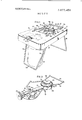
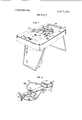
- FIG. I is a perspective view of one embodiment of the portable stove according to the invention.
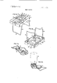
- FIG. 1a is a perspective view of only the portable stand of FIG. 1 with the burner apparatus and disposable fuel cartridge removed,
- FIG. lb is a bottom perspective view of the underside of the stand of FIG. Ia,
- FIG. 2 is a perspective front view of the burner apparatus alone
- FIG. 2a is a perspective from view of the burner from opposite side relative to FIG. 2,
- FIG. 2b is a bottom perspective view of the burner apparatus
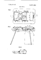
- FIG. 3 is a plan view of the top of the stove
- FIG. 4 is a sectional view of the stove along line 4-4 in FIG. 3,
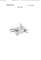
- FIG. 5 is a sectional view of the burner head
- FIG. 6 is a sectional view of the valve housing.
- FIGS. 7 and 8 are views similar to FIGS. 1 and 2 of another embodiment of the stove.
- the stove comprises a burner apparatus 10, a stand II, for supporting the burner apparatus and a disposable fuel cartridge 12 of standard type for liquified butane.
- a cooking utensil such as a saucepan with a bottom l3 may be placed on the stove as indicated in FIG. 4.
- the fuel cartridge I2 is a cylindrical container which at its top end has an opening for inserting a connecting pipe 14 of the valve housing 15 (FIG. 2b).
- a non-return valve is opened for admitting fuel liquid through the connecting pipe into the valve housing 15 of the burner apparatus.
- the stand II comprises an inverted trough of sheet metal having a top plate 16 and a closed frame defined by side flanges 17.
- a pair of rear legs 18, I8 and front legs I9, l9 are pivotally mounted to the flanges l7 and may be collapsed to a position under the top plate and within the frame formed by side flanges I7.
- the front legs. [9 are formed by a U-shaped wire having a horizontal intermediate portion 20 which may be moved to a position under the bottom of the cartridge 12 (dotted line position) to secure the cartridge to the burner apparatus as illustrated in FIGS. 1, 2b and 4.
- Small lugs 21 are welded to the inside of the flanges l7 and are provided with holes for receiving the ends of the legs I8, 19 as shown in FIG. lb.
- the top plate 16 is provided with two longitudinal parallel spaced slots 22, 23.
- the portion of the top plate between the slots is divided by means of transverse slots 24, 25 into two bottom portions 26, 27 connected to the top plate by sloping oppsoite end walls 28, 29 so that the bottom portions are located in a lowered position at a level about half of the height of the flanges 27.
- One of the end walls has a central longitudinal slot 30. The end edges of the bottom portions 26, 27 have been cut to form an opening 31 for the burner head 32.
- the valve housing 15 is secured by one or more screws 15a to the underside of the top plate.
- valve housing At opposite ends of the valve housing are axially extending studs 33, 34 having cylindrical bores 35, 36.
- a vertical bore 37 In the bottom of the valve housing is a vertical bore 37 (FIG. 6) in which the connecting pipe I4 is mounted. Liquid fuel enters the vertical bore and passes through a channel 38 to a metering valve having a valve member 39 at the end of a control rod 40 which by means of threads is axially movable in the stud 33.
- the control rod 40 has a control knob 41 which is mounted so that a portion thereof projects through an aperture 42 in the top plate. The aperture permits desired axial movement of the knob 41, but the outer edge 43 of the aperture forms a stop member preventing the rod from being disengaged from the stud 33.
- a tube 51 Inserted into the stud 34 is one end portion of a tube 51, which at its other end supports the burner head 32.
- the tube 51 is provided with a primary air opening 52.
- the mixture of vaporized fuel and air enters the burner head and flows upwardly to a spreader member 53 in the form ofa frustoconical member having a plurality of gas outlet openings.
- the gas outlet openings are positioned close to the bottom 13 of the saucepan or similar utensil placed on the stove.
- the tube 51 of the burner apparatus passes freely through the central slot 30 in the bottom portion 26 and wall 29.
- the burner head 32 is positioned between the opposite recessed edges of the bottom portions 26, 27.
- the edge 27a of the bottom portion 27 forms an axial stop for the burner head 32 to keep its tube SI in position on the stud 34 of the valve housing.
- the flanges l7 form a windshield around the burner apparatus and its burner head and due to the fact that the top plate will have a recessed portion in the region around the burner head because of the lowered position of the bottom portions 26, 27', there will be an enlarged partially closed space around the burner head so that the main portion of the secondary air will enter through the windshielded slots 22, 23, 24, 25 in the top plate into said space.
- the combustion gases and the flames can leave said space through the relative narrow gap between the bottom 13 (FIG. 4) of the cooking utensil and the top plate 16.
- the slots 22, 23, 24, 25 have a wind shielded position behind the flanges so that the air flow through the slots will be relatively steady also when the stove is used under weather conditions with strong winds.
- the vaporizing tube 46 In order to obtain an effective heating ofthe vaporizing tube 46 it is shaped as a loop having at least one portion located in the vicinity of the burner head so that the flames will effectively heat the tube as will be understood from FIGS. 1 and 7.
- the configuration of the loop of the vaporizing tube may generally have the shape indicated in FIGS. 1 and 2 or as an alternative as indicated in FIGS. 7 and 8.
- At least some of the members for supporting the cooking utensil with its bottom at a desired closely spaced distance above the burner head are comprised of portions of the vaporizing tube which to this end is bent locally at the places shown in FIGS. 2 and 8 to form upwardly projecting supporting feet.
- FIGS. I and 2 there are four such supporting feet 57, 58, 59. and 60. and in the embodiment of FIGS. 7 and 8 the vaporizing tube is formed with two supporting feet 62, 64, which together with a rear support member 65 secured to the plate 16 form the supporting members for the cooking utensil.
- the position of the main part of the vaporizing tube will be located in the region of the flames. that is in the small gap between the top plate 16 and the bottom 13 of the cooking utensil as will be understood from FIG. 4.
- the longer loop of the vaporizing tube in FIG. 2 is used to form two side legs 65, 66 having inwardly extended bends 67, 68 in one and the same plane so that the inner ends 69, 70 of the bends will rest on the burner head and prevent rotation of the same on the stud 34 of the valve housing.
- the side legs 67. 68 are connected by a transversely aligned end connecting portion 71 which rests on the top plate 16. Accord ingly the forces on the feet 57, 58, 59. 60 will be transmitted to the top plate via the transverse portion 71 and the screw or screws 15a securing the valve housing to the top plate.
- a long vaporizing tube will extend the time between adjustment of the knob 41 and the corre sponding change of the flame, and therefore it may in some applications be convenient to have a shorter va porizing tube such as the tube 46 shown in FIGS. 7 and 8.
- the vaporizing tube 46 extends in a transverse loop portion 72 between the feet 62, 64 and engages the burner head 32 to prevent rotation of the same on the stud 34.
- the flames will effectively heat the vaporising tube. but the extra member 65 will complicate the manufacture to some extent. and further the attachment of the burner apparatus must be designed with respect to increased forces on the screw 15a.
- a burner assembly comprising:
- a housing having a first inlet opening
- a hollow elongated vaporizing tube having its free ends respectively coupled to the first outlet opening and second inlet opening of said housing for delivering fuel from said cartridge to said burner ap paratus;
- said vaporizing tube having at least an intermediate portion thereof positioned in close proximity to said burner head for heating said vaporizing tube during the burning of fuel to vaporize the fuel flowing through the vaporizing tube as the fuel is fed to the burner head;
- said vaporizing tube being bent to form a support for a utensil positioned above the burner head.
- a stove as defined in claim I in which the loop of the vaporizing tube extends around the burner head and has two side legs on opposite sides of the burner head and a transverse leg connecting the ends of the side legs.
- the vaporizing tube being formed with local upwardly extending bends to provide supporting feet at the ends of said legs to support a cooking utensil, with said transverse leg resting on the upper side of the top surface.
- a stove as defined in claim I in which said loop has a transverse middle portion positioned on the same side of the burner head as the valve housing and in close proximity to the burner head 4.
- the burner head connecting tube is loosely inserted and rotatable about a stud projecting from the valve housing second outlet opening and said loop of the vaporizing tube is formed with at least one portion engaging the burner head to prevent rotation thereof on said stud.
- a portabie stove comprising:
- a stand for supporting said burner assembly said stand including means for releasably securing a disposable fuel cartridge to said stand;
- said stand comprising a metallic sheet forming a top surface and downwardly depending side flanges;
- said burner assembly comprising a valve housing se cured to the underside of said top surface and having means for releasable coupling to a fuel cartridge outlet;
- a burner head ; an outlet opening in said housing; a tube connecting the burner head to the housing outlet opening;
- a hollow elongated vaporizing pipe extending between a pair of openings in said valve housing for coupling the inlet coupling means to the housing outlet opening;
- said top surface having a recessed opening for receiv ing said burner head
- said vaporizing pipe being arranged to form a loop having a portion thereof in close proximity to said burner head for vaporizing fuel passing therethrough towards said burner head;
- the looped portion of the vaporizing pipe serving as a means for supporting a cooking utensil a spaced distance above said burner head.
- valve housing further comprises valve means for regulating the rate of flow of fuel entering into said vaporizing pipe.
- the portable stove of claim 5 further comprising a first and second set of supporting legs pivotally secured to the underside of said stand for supporting said stand when in the extended position and being confined within said side flanges when in the collapsed position;
- said cartridge securing means comprising one of said legs and having a U-shaped configuration adapted to support a fuel cartridge therebetween when in the extended position.
Landscapes
- Engineering & Computer Science (AREA)
- Chemical & Material Sciences (AREA)
- Combustion & Propulsion (AREA)
- Mechanical Engineering (AREA)
- General Engineering & Computer Science (AREA)
- Feeding And Controlling Fuel (AREA)
Abstract
A collapsible weight small sized portable stove for butane fuel from a disposable cartridge. The vaporizing or preheating tube is in the form of a loop having at least one portion located in the region passed by the flames and being formed and positioned for supporting a cooking utensil such as a saucepan.
Description
United States Patent [191 Allander 1 Apr. 15, 1975 1 PORTABLE STOVE [75] Inventor: Claes Vilhelm Allander, Stockholm,
Sweden [73] Assignee: Aktiebolaget Optimus, Upplands Vasby, Sweden [22] Filed: Feb. 4, 1974 [21] App1.No.:438,521
[30} Foreign Application Priority Data Feb. 2, 1973 Sweden 7301471 [52] U.S. Cl 126/44; 126/9 R; 126/38; 126/50; 431/247 [51] Int. Cl. F24c 5/20 [58] Field of Search 126/44, 38, 50, 9 R; 431/247 [56] References Cited UNITED STATES PATENTS 476,694 6/1892 Smith 431/247 1,105,079 7/1914 Hovenden 126/44 2,325,077 7/1943 Robinson 126/38 2,969,054 1/1961 Axelsson 126/38 FOREIGN PATENTS OR APPLICATIONS 344,541 3/1960 Switzerland 126/44 Primary Examiner-Carroll B. Dority, Jr.
Assistant Examinerl-larold Joyce Attorney, Agent, or Firm-Ostrolenk, Faber, Gerb & Soffen [57] ABSTRACT A collapsible weight small sized portable stove for butane fuel from a disposable cartridge. The vaporizing or preheating tube is in the form of a loop having at least one portion located in the region passed by the flames and being formed and positioned for supporting a cooking utensil such as a saucepan.
9 Claims, 12 Drawing Figures FQTENTEB APR 1 5 (51 5 SHEET 2 BF PMENTEBAPR 1 5197s snzmauw FIGA PORTABLE srovs The present invention relates to a portable stove comprising a burner apparatus and a stove stand for supporting the burner and a disposable cartridge for liquified gas such as butane.
The general object of the invention is to provide a portable stove which is intended for liquifled fuel gas such as butane and which may be collapsed to small dimensions when not in use and which has a preheating tube for effectively vaporising the liquified gas before entering the burner head of the burner apparatus.
Another object ofthe invention is to provide a portable stove having simple windshield means which will reduce the influence of wind on the flame and on the vaporising tube so that the flame will be kept relatively steady and the vaporising tube will be kept at a high temperature and reach the desired temperature quickly when starting up the stove.
These and other objects will be attained with the invention as explained more in detail in the following specification with reference to the accompanying drawings showing by way of example preferred embodiments of the inventive stove, the features of which being set forth in the claims.
IN THE DRAWINGS FIG. I is a perspective view of one embodiment of the portable stove according to the invention,
FIG. 1a is a perspective view of only the portable stand of FIG. 1 with the burner apparatus and disposable fuel cartridge removed,
FIG. lb is a bottom perspective view of the underside of the stand of FIG. Ia,
FIG. 2 is a perspective front view of the burner apparatus alone,
FIG. 2a is a perspective from view of the burner from opposite side relative to FIG. 2,
FIG. 2b is a bottom perspective view of the burner apparatus,
FIG. 3 is a plan view of the top of the stove,
FIG. 4 is a sectional view of the stove along line 4-4 in FIG. 3,
FIG. 5 is a sectional view of the burner head,
FIG. 6 is a sectional view of the valve housing.
FIGS. 7 and 8 are views similar to FIGS. 1 and 2 of another embodiment of the stove.
With reference to FIGS. I to 6, the stove comprises a burner apparatus 10, a stand II, for supporting the burner apparatus and a disposable fuel cartridge 12 of standard type for liquified butane. A cooking utensil such as a saucepan with a bottom l3 may be placed on the stove as indicated in FIG. 4.
The fuel cartridge I2 is a cylindrical container which at its top end has an opening for inserting a connecting pipe 14 of the valve housing 15 (FIG. 2b). When the pipe 14 is inserted in the cartridge. a non-return valve is opened for admitting fuel liquid through the connecting pipe into the valve housing 15 of the burner apparatus.
The stand II comprises an inverted trough of sheet metal having a top plate 16 and a closed frame defined by side flanges 17. A pair of rear legs 18, I8 and front legs I9, l9 are pivotally mounted to the flanges l7 and may be collapsed to a position under the top plate and within the frame formed by side flanges I7. The front legs. [9 are formed by a U-shaped wire having a horizontal intermediate portion 20 which may be moved to a position under the bottom of the cartridge 12 (dotted line position) to secure the cartridge to the burner apparatus as illustrated in FIGS. 1, 2b and 4.
The top plate 16 is provided with two longitudinal parallel spaced slots 22, 23. The portion of the top plate between the slots is divided by means of transverse slots 24, 25 into two bottom portions 26, 27 connected to the top plate by sloping oppsoite end walls 28, 29 so that the bottom portions are located in a lowered position at a level about half of the height of the flanges 27. One of the end walls has a central longitudinal slot 30. The end edges of the bottom portions 26, 27 have been cut to form an opening 31 for the burner head 32.
The valve housing 15 is secured by one or more screws 15a to the underside of the top plate.
At opposite ends of the valve housing are axially extending studs 33, 34 having cylindrical bores 35, 36. In the bottom of the valve housing is a vertical bore 37 (FIG. 6) in which the connecting pipe I4 is mounted. Liquid fuel enters the vertical bore and passes through a channel 38 to a metering valve having a valve member 39 at the end of a control rod 40 which by means of threads is axially movable in the stud 33. The control rod 40 has a control knob 41 which is mounted so that a portion thereof projects through an aperture 42 in the top plate. The aperture permits desired axial movement of the knob 41, but the outer edge 43 of the aperture forms a stop member preventing the rod from being disengaged from the stud 33. When the metering valve is open, the fuel flows into a transverse bore 44 (FIG. 6) to which one end 45 ofthe vaporizing tube 46 is connected. The other end 48 of the vaporizing tube is connected to another transverse bore 49 in the valve housing and this bore is in communication with the axial bore 36 in the stud. At the end of bore 36 is an orifice 50.
Inserted into the stud 34 is one end portion of a tube 51, which at its other end supports the burner head 32. The tube 51 is provided with a primary air opening 52.
The mixture of vaporized fuel and air enters the burner head and flows upwardly to a spreader member 53 in the form ofa frustoconical member having a plurality of gas outlet openings. As will be understood from FIG. 4, the gas outlet openings are positioned close to the bottom 13 of the saucepan or similar utensil placed on the stove.
The tube 51 of the burner apparatus passes freely through the central slot 30 in the bottom portion 26 and wall 29. The burner head 32 is positioned between the opposite recessed edges of the bottom portions 26, 27. However, the edge 27a of the bottom portion 27 forms an axial stop for the burner head 32 to keep its tube SI in position on the stud 34 of the valve housing.
As will be understood particularly from FIG. 4, the flanges l7 form a windshield around the burner apparatus and its burner head and due to the fact that the top plate will have a recessed portion in the region around the burner head because of the lowered position of the bottom portions 26, 27', there will be an enlarged partially closed space around the burner head so that the main portion of the secondary air will enter through the windshielded slots 22, 23, 24, 25 in the top plate into said space. The combustion gases and the flames can leave said space through the relative narrow gap between the bottom 13 (FIG. 4) of the cooking utensil and the top plate 16. The slots 22, 23, 24, 25 have a wind shielded position behind the flanges so that the air flow through the slots will be relatively steady also when the stove is used under weather conditions with strong winds.
In order to obtain an effective heating ofthe vaporizing tube 46 it is shaped as a loop having at least one portion located in the vicinity of the burner head so that the flames will effectively heat the tube as will be understood from FIGS. 1 and 7.
The configuration of the loop of the vaporizing tube may generally have the shape indicated in FIGS. 1 and 2 or as an alternative as indicated in FIGS. 7 and 8.
In order to simplify the construction of the stove at least some of the members for supporting the cooking utensil with its bottom at a desired closely spaced distance above the burner head are comprised of portions of the vaporizing tube which to this end is bent locally at the places shown in FIGS. 2 and 8 to form upwardly projecting supporting feet. In FIGS. I and 2 there are four such supporting feet 57, 58, 59. and 60. and in the embodiment of FIGS. 7 and 8 the vaporizing tube is formed with two supporting feet 62, 64, which together with a rear support member 65 secured to the plate 16 form the supporting members for the cooking utensil.
By using part of the vaporizing tube 46 in FIG. 1 or 46a in H05. 7 and 8 as a support for the cooking utensil. the position of the main part of the vaporizing tube will be located in the region of the flames. that is in the small gap between the top plate 16 and the bottom 13 of the cooking utensil as will be understood from FIG. 4.
The main difference between the embodiments in FIG. 2 and FIG. 8 of the vaporizing tube respectively is that the loop of the vaporizing tube 46 in FIG. 2 is much longer than the loop of the vaporizing tube 46a in FIG. 8.
The longer loop of the vaporizing tube in FIG. 2 is used to form two side legs 65, 66 having inwardly extended bends 67, 68 in one and the same plane so that the inner ends 69, 70 of the bends will rest on the burner head and prevent rotation of the same on the stud 34 of the valve housing. The side legs 67. 68 are connected by a transversely aligned end connecting portion 71 which rests on the top plate 16. Accord ingly the forces on the feet 57, 58, 59. 60 will be transmitted to the top plate via the transverse portion 71 and the screw or screws 15a securing the valve housing to the top plate.
However. a long vaporizing tube will extend the time between adjustment of the knob 41 and the corre sponding change of the flame, and therefore it may in some applications be convenient to have a shorter va porizing tube such as the tube 46 shown in FIGS. 7 and 8. In this embodiment the vaporizing tube 46:: extends in a transverse loop portion 72 between the feet 62, 64 and engages the burner head 32 to prevent rotation of the same on the stud 34. Also in this embodiment the flames will effectively heat the vaporising tube. but the extra member 65 will complicate the manufacture to some extent. and further the attachment of the burner apparatus must be designed with respect to increased forces on the screw 15a.
What I claim is:
l. A burner assembly comprising:
a housing having a first inlet opening;
an inlet pipe extending from said housing first inlet opening for releasable attachment to a fuel cartridge;
a burner head;
a connecting tube coupled between said housing and said burner head;
a first outlet opening in said housing;
a first passageway in said housing extending between said first inlet and said first outlet opening;
a second inlet opening and a second outlet opening in said housing;
a second passageway extending between said second inlet and outlet openings; said connecting tube communicating with said second outlet opening;
a hollow elongated vaporizing tube having its free ends respectively coupled to the first outlet opening and second inlet opening of said housing for delivering fuel from said cartridge to said burner ap paratus;
said vaporizing tube having at least an intermediate portion thereof positioned in close proximity to said burner head for heating said vaporizing tube during the burning of fuel to vaporize the fuel flowing through the vaporizing tube as the fuel is fed to the burner head;
said vaporizing tube being bent to form a support for a utensil positioned above the burner head.
2. A stove as defined in claim I, in which the loop of the vaporizing tube extends around the burner head and has two side legs on opposite sides of the burner head and a transverse leg connecting the ends of the side legs. the vaporizing tube being formed with local upwardly extending bends to provide supporting feet at the ends of said legs to support a cooking utensil, with said transverse leg resting on the upper side of the top surface.
3. A stove as defined in claim I, in which said loop has a transverse middle portion positioned on the same side of the burner head as the valve housing and in close proximity to the burner head 4. A stove as defined in claim I, in which the burner head connecting tube is loosely inserted and rotatable about a stud projecting from the valve housing second outlet opening and said loop of the vaporizing tube is formed with at least one portion engaging the burner head to prevent rotation thereof on said stud.
5. A portabie stove comprising:
a burner assembly;
a stand for supporting said burner assembly, said stand including means for releasably securing a disposable fuel cartridge to said stand;
said stand comprising a metallic sheet forming a top surface and downwardly depending side flanges;
said burner assembly comprising a valve housing se cured to the underside of said top surface and having means for releasable coupling to a fuel cartridge outlet;
a burner head; an outlet opening in said housing; a tube connecting the burner head to the housing outlet opening;
a hollow elongated vaporizing pipe extending between a pair of openings in said valve housing for coupling the inlet coupling means to the housing outlet opening;
said top surface having a recessed opening for receiv ing said burner head;
said vaporizing pipe being arranged to form a loop having a portion thereof in close proximity to said burner head for vaporizing fuel passing therethrough towards said burner head;
the looped portion of the vaporizing pipe serving as a means for supporting a cooking utensil a spaced distance above said burner head.
6. The portable stove of claim 5, wherein said valve housing further comprises valve means for regulating the rate of flow of fuel entering into said vaporizing pipe.
7. The portable stove of claim 5, wherein said top surface is provided with slots adjacent said opening for 6 positioning and supporting the vaporizing pipe.
8. A stove as defined in claim 7, in which the recessed slotted portion of said top surface is positioned intermediate the top surface and the bottom edges of the side flanges.
9. The portable stove of claim 5, further comprising a first and second set of supporting legs pivotally secured to the underside of said stand for supporting said stand when in the extended position and being confined within said side flanges when in the collapsed position;
said cartridge securing means comprising one of said legs and having a U-shaped configuration adapted to support a fuel cartridge therebetween when in the extended position.
Claims (9)
1. A burner assembly comprising: a housing having a first inlet opening; an inlet pipe extending from said housing first inlet opening for releasable attachment to a fuel cartridge; a burner head; a connecting tube coupled between said housing and said burner head; a first outlet opening in said housing; a first passageway in said housing extending between said first inlet and said first outlet opening; a second inlet opening and a second outlet opening in said housing; a second passageway extending between said second inlet and outlet openings; said connecting tube communicating with said second outlet opening; a hollow elongated vaporizing tube having its free ends respectively coupled to the first outlet opening and second inlet opening of said housing for delivering fuel from said cartridge to said burner apparatus; said vaporizing tube having at least an intermediate portion thereof positioned in close proximity to said burner head for heating said vaporizing tube during the burning oF fuel to vaporize the fuel flowing through the vaporizing tube as the fuel is fed to the burner head; said vaporizing tube being bent to form a support for a utensil positioned above the burner head.
2. A stove as defined in claim 1, in which the loop of the vaporizing tube extends around the burner head and has two side legs on opposite sides of the burner head and a transverse leg connecting the ends of the side legs, the vaporizing tube being formed with local upwardly extending bends to provide supporting feet at the ends of said legs to support a cooking utensil, with said transverse leg resting on the upper side of the top surface.
3. A stove as defined in claim 1, in which said loop has a transverse middle portion positioned on the same side of the burner head as the valve housing and in close proximity to the burner head.
4. A stove as defined in claim 1, in which the burner head connecting tube is loosely inserted and rotatable about a stud projecting from the valve housing second outlet opening and said loop of the vaporizing tube is formed with at least one portion engaging the burner head to prevent rotation thereof on said stud.
5. A portable stove comprising: a burner assembly; a stand for supporting said burner assembly, said stand including means for releasably securing a disposable fuel cartridge to said stand; said stand comprising a metallic sheet forming a top surface and downwardly depending side flanges; said burner assembly comprising a valve housing secured to the underside of said top surface and having means for releasable coupling to a fuel cartridge outlet; a burner head; an outlet opening in said housing; a tube connecting the burner head to the housing outlet opening; a hollow elongated vaporizing pipe extending between a pair of openings in said valve housing for coupling the inlet coupling means to the housing outlet opening; said top surface having a recessed opening for receiving said burner head; said vaporizing pipe being arranged to form a loop having a portion thereof in close proximity to said burner head for vaporizing fuel passing therethrough towards said burner head; the looped portion of the vaporizing pipe serving as a means for supporting a cooking utensil a spaced distance above said burner head.
6. The portable stove of claim 5, wherein said valve housing further comprises valve means for regulating the rate of flow of fuel entering into said vaporizing pipe.
7. The portable stove of claim 5, wherein said top surface is provided with slots adjacent said opening for positioning and supporting the vaporizing pipe.
8. A stove as defined in claim 7, in which the recessed slotted portion of said top surface is positioned intermediate the top surface and the bottom edges of the side flanges.
9. The portable stove of claim 5, further comprising a first and second set of supporting legs pivotally secured to the underside of said stand for supporting said stand when in the extended position and being confined within said side flanges when in the collapsed position; said cartridge securing means comprising one of said legs and having a U-shaped configuration adapted to support a fuel cartridge therebetween when in the extended position.
Applications Claiming Priority (1)
| Application Number | Priority Date | Filing Date | Title |
|---|---|---|---|
| SE7301471A SE7301471L (en) | 1973-02-02 |
Publications (1)
| Publication Number | Publication Date |
|---|---|
| US3877458A true US3877458A (en) | 1975-04-15 |
Family
ID=20316515
Family Applications (1)
| Application Number | Title | Priority Date | Filing Date |
|---|---|---|---|
| US438521A Expired - Lifetime US3877458A (en) | 1973-02-02 | 1974-02-04 | Portable stove |
Country Status (1)
| Country | Link |
|---|---|
| US (1) | US3877458A (en) |
Cited By (36)
| Publication number | Priority date | Publication date | Assignee | Title |
|---|---|---|---|---|
| US4078540A (en) * | 1976-07-06 | 1978-03-14 | Beshing Hou | Kerosene vapor stove with automatic fuel feeding system |
| EP0005677A1 (en) * | 1978-04-24 | 1979-11-28 | Application Des Gaz | Improvements in gas cookers with two burners fed by gas under pressure contained in a tank |
| US4334516A (en) * | 1978-11-15 | 1982-06-15 | Ellen Dittmer | Collapsible, portable barbecue grill |
| US4353347A (en) * | 1979-05-11 | 1982-10-12 | Barba Grill Inc. | Portable cooker |
| US4385619A (en) * | 1980-08-18 | 1983-05-31 | Casinelli Dominic L | Portable stove |
| WO1989009911A1 (en) * | 1988-04-11 | 1989-10-19 | Clapp Clarence P | Combustion apparatus and method for combusting a pressurized fuel |
| US4899722A (en) * | 1988-09-02 | 1990-02-13 | Horewitch Richard L | Burner assembly for heating chafing dishes |
| US5080580A (en) * | 1988-04-11 | 1992-01-14 | Clapp Clarence P | Combustion apparatus and method for combusting a pressurized fuel |
| US5307798A (en) * | 1993-06-07 | 1994-05-03 | Overmars Sr Ben J A | Pad for portable stove |
| EP0703409A1 (en) * | 1994-08-13 | 1996-03-27 | Coleman Taymar Limited | An LPG burning appliance |
| USD392506S (en) | 1997-05-08 | 1998-03-24 | Church Thomas E | Backpack stove stand |
| USD394782S (en) | 1996-06-14 | 1998-06-02 | Church Thomas E | Backpack stove stand |
| US5782449A (en) * | 1996-06-14 | 1998-07-21 | Church; Thomas E. | Backpack stove stand |
| US5803727A (en) * | 1997-01-30 | 1998-09-08 | The Coleman Company, Inc. | Burner assembly for burning appliances |
| FR2763256A1 (en) * | 1997-05-14 | 1998-11-20 | Air Liquide | Vaporisation of a hydrocarbon mixture to calibrate gas chromatographs |
| US5975884A (en) * | 1997-10-24 | 1999-11-02 | H. Barry Bone | Stand-alone device for igniting, regulating and operating gas appliances |
| US5983883A (en) * | 1996-12-10 | 1999-11-16 | Moulder; Charles R. | Mounting apparatus for portable stoves |
| WO1999064140A1 (en) * | 1998-06-10 | 1999-12-16 | L'air Liquide, Societe Anonyme Pour L'etude Et L'exploitation Des Procedes Georges Claude | Method and unit for evaporating a hydrocarbon liquid mixture |
| US6042368A (en) * | 1998-02-03 | 2000-03-28 | The Coleman Company, Inc. | Appliance for burning a combustible gas, and method of burning such a gas |
| US6237891B1 (en) | 1999-09-08 | 2001-05-29 | Burnswick Corporation | Adaptor for use of alternate gas fuel |
| USD443462S1 (en) | 2000-04-03 | 2001-06-12 | Lucas Pai | Barbecue grill |
| USD447002S1 (en) | 2000-04-03 | 2001-08-28 | Lucas Pai | Charcoal grill stand |
| US6331108B1 (en) | 1999-10-18 | 2001-12-18 | Brunswick Corporation | Convertible gas-burning appliance |
| US20030145846A1 (en) * | 2001-10-31 | 2003-08-07 | Brent Purcell | Fuel pre-heating device |
| US6641000B2 (en) | 2001-03-27 | 2003-11-04 | Jack Lange | Fuel conduction system |
| WO2009094677A3 (en) * | 2008-01-25 | 2009-12-10 | Buzbee (Pty) Ltd | A fuel burner system |
| USD610390S1 (en) * | 2009-01-21 | 2010-02-23 | Shinfuji Burner Co., Ltd. | Portable gas cooking stove |
| USD612662S1 (en) * | 2009-04-10 | 2010-03-30 | EnviroFit International, Ltd. | Stove |
| US20100175563A1 (en) * | 2008-12-18 | 2010-07-15 | Michael John Bizal | Wide flanged frying/cooking device with stand and safety plate |
| USD640497S1 (en) | 2009-04-10 | 2011-06-28 | EnviroFit International, Ltd. | Dual burner |
| US20150192301A1 (en) * | 2014-01-07 | 2015-07-09 | Kovea Co., Ltd. | Nozzle structure of burner |
| CN104990109A (en) * | 2015-07-10 | 2015-10-21 | 芜湖鸣人热能设备有限公司 | Portable fuel gas furnace |
| EP2989391A4 (en) * | 2013-04-23 | 2017-01-18 | Johnson Outdoors, Inc. | High performance outdoor portable cooking system |
| US9788689B2 (en) | 2008-12-18 | 2017-10-17 | Fryin' Saucer, Inc. | Wide flanged cooking device with collapsible stand |
| USD898183S1 (en) * | 2017-02-04 | 2020-10-06 | Dongsheng Zhou | Mesh structure for a gas burner |
| KR102455991B1 (en) * | 2022-04-26 | 2022-10-18 | (주)오빌 | Supporting Device for Burner with Legs on which a Cooker is put |
Citations (4)
| Publication number | Priority date | Publication date | Assignee | Title |
|---|---|---|---|---|
| US476694A (en) * | 1892-06-07 | smith | ||
| US1105079A (en) * | 1914-02-21 | 1914-07-28 | William F Meidroth | Hydrocarbon-burner. |
| US2325077A (en) * | 1942-07-07 | 1943-07-27 | Robinson Bestor | Folding stove |
| US2969054A (en) * | 1957-12-05 | 1961-01-24 | Bahco Ab | Cooking appliances burning a gaseous fuel |
-
1974
- 1974-02-04 US US438521A patent/US3877458A/en not_active Expired - Lifetime
Patent Citations (4)
| Publication number | Priority date | Publication date | Assignee | Title |
|---|---|---|---|---|
| US476694A (en) * | 1892-06-07 | smith | ||
| US1105079A (en) * | 1914-02-21 | 1914-07-28 | William F Meidroth | Hydrocarbon-burner. |
| US2325077A (en) * | 1942-07-07 | 1943-07-27 | Robinson Bestor | Folding stove |
| US2969054A (en) * | 1957-12-05 | 1961-01-24 | Bahco Ab | Cooking appliances burning a gaseous fuel |
Cited By (39)
| Publication number | Priority date | Publication date | Assignee | Title |
|---|---|---|---|---|
| US4078540A (en) * | 1976-07-06 | 1978-03-14 | Beshing Hou | Kerosene vapor stove with automatic fuel feeding system |
| EP0005677A1 (en) * | 1978-04-24 | 1979-11-28 | Application Des Gaz | Improvements in gas cookers with two burners fed by gas under pressure contained in a tank |
| US4334516A (en) * | 1978-11-15 | 1982-06-15 | Ellen Dittmer | Collapsible, portable barbecue grill |
| US4353347A (en) * | 1979-05-11 | 1982-10-12 | Barba Grill Inc. | Portable cooker |
| US4385619A (en) * | 1980-08-18 | 1983-05-31 | Casinelli Dominic L | Portable stove |
| WO1989009911A1 (en) * | 1988-04-11 | 1989-10-19 | Clapp Clarence P | Combustion apparatus and method for combusting a pressurized fuel |
| US5080580A (en) * | 1988-04-11 | 1992-01-14 | Clapp Clarence P | Combustion apparatus and method for combusting a pressurized fuel |
| US4899722A (en) * | 1988-09-02 | 1990-02-13 | Horewitch Richard L | Burner assembly for heating chafing dishes |
| US5307798A (en) * | 1993-06-07 | 1994-05-03 | Overmars Sr Ben J A | Pad for portable stove |
| EP0703409A1 (en) * | 1994-08-13 | 1996-03-27 | Coleman Taymar Limited | An LPG burning appliance |
| USD394782S (en) | 1996-06-14 | 1998-06-02 | Church Thomas E | Backpack stove stand |
| US5782449A (en) * | 1996-06-14 | 1998-07-21 | Church; Thomas E. | Backpack stove stand |
| US5983883A (en) * | 1996-12-10 | 1999-11-16 | Moulder; Charles R. | Mounting apparatus for portable stoves |
| US5803727A (en) * | 1997-01-30 | 1998-09-08 | The Coleman Company, Inc. | Burner assembly for burning appliances |
| USD392506S (en) | 1997-05-08 | 1998-03-24 | Church Thomas E | Backpack stove stand |
| FR2763256A1 (en) * | 1997-05-14 | 1998-11-20 | Air Liquide | Vaporisation of a hydrocarbon mixture to calibrate gas chromatographs |
| US5975884A (en) * | 1997-10-24 | 1999-11-02 | H. Barry Bone | Stand-alone device for igniting, regulating and operating gas appliances |
| US6042368A (en) * | 1998-02-03 | 2000-03-28 | The Coleman Company, Inc. | Appliance for burning a combustible gas, and method of burning such a gas |
| WO1999064140A1 (en) * | 1998-06-10 | 1999-12-16 | L'air Liquide, Societe Anonyme Pour L'etude Et L'exploitation Des Procedes Georges Claude | Method and unit for evaporating a hydrocarbon liquid mixture |
| US6237891B1 (en) | 1999-09-08 | 2001-05-29 | Burnswick Corporation | Adaptor for use of alternate gas fuel |
| US6331108B1 (en) | 1999-10-18 | 2001-12-18 | Brunswick Corporation | Convertible gas-burning appliance |
| USD443462S1 (en) | 2000-04-03 | 2001-06-12 | Lucas Pai | Barbecue grill |
| USD447002S1 (en) | 2000-04-03 | 2001-08-28 | Lucas Pai | Charcoal grill stand |
| US6641000B2 (en) | 2001-03-27 | 2003-11-04 | Jack Lange | Fuel conduction system |
| US6863524B2 (en) * | 2001-10-31 | 2005-03-08 | Brent Purcell | Fuel pre-heating device |
| US20030145846A1 (en) * | 2001-10-31 | 2003-08-07 | Brent Purcell | Fuel pre-heating device |
| WO2009094677A3 (en) * | 2008-01-25 | 2009-12-10 | Buzbee (Pty) Ltd | A fuel burner system |
| US9737170B2 (en) * | 2008-12-18 | 2017-08-22 | Fryin' Saucer, Inc. | Wide flanged frying/cooking device with stand and safety plate |
| US20100175563A1 (en) * | 2008-12-18 | 2010-07-15 | Michael John Bizal | Wide flanged frying/cooking device with stand and safety plate |
| US9788689B2 (en) | 2008-12-18 | 2017-10-17 | Fryin' Saucer, Inc. | Wide flanged cooking device with collapsible stand |
| USD610390S1 (en) * | 2009-01-21 | 2010-02-23 | Shinfuji Burner Co., Ltd. | Portable gas cooking stove |
| USD612662S1 (en) * | 2009-04-10 | 2010-03-30 | EnviroFit International, Ltd. | Stove |
| USD640497S1 (en) | 2009-04-10 | 2011-06-28 | EnviroFit International, Ltd. | Dual burner |
| EP2989391A4 (en) * | 2013-04-23 | 2017-01-18 | Johnson Outdoors, Inc. | High performance outdoor portable cooking system |
| US20150192301A1 (en) * | 2014-01-07 | 2015-07-09 | Kovea Co., Ltd. | Nozzle structure of burner |
| US10072838B2 (en) * | 2014-01-07 | 2018-09-11 | Kovea Co., Ltd. | Nozzle structure of burner |
| CN104990109A (en) * | 2015-07-10 | 2015-10-21 | 芜湖鸣人热能设备有限公司 | Portable fuel gas furnace |
| USD898183S1 (en) * | 2017-02-04 | 2020-10-06 | Dongsheng Zhou | Mesh structure for a gas burner |
| KR102455991B1 (en) * | 2022-04-26 | 2022-10-18 | (주)오빌 | Supporting Device for Burner with Legs on which a Cooker is put |
Similar Documents
| Publication | Publication Date | Title |
|---|---|---|
| US3877458A (en) | Portable stove | |
| US3933146A (en) | Portable single burner campstove | |
| US3399024A (en) | Burner construction and the like | |
| US2526748A (en) | Gas burner with adjustable flame slot and central secondary air supply | |
| US2960157A (en) | Gas burner | |
| US3210537A (en) | Portable lantern | |
| JPS6314164Y2 (en) | ||
| US4542733A (en) | Portable gas fired barbecue | |
| US4126117A (en) | Portable single burner campstove | |
| US2304706A (en) | Attachment for oil burners | |
| US2759471A (en) | Top burner assembly for gas stove | |
| US1530079A (en) | Liquid-fuel-burning apparatus | |
| US2694445A (en) | Mixing tube for gas burners | |
| USRE31738E (en) | Portable single burner campstove | |
| US2128155A (en) | Oil burner | |
| US2396675A (en) | Liquid fuel burner | |
| US2799329A (en) | Gas burner | |
| US1885891A (en) | Ration | |
| US4397632A (en) | Vaporized type liquid fuel combustion apparatus | |
| US2721546A (en) | Liquid fuel heating apparatus | |
| US2682303A (en) | Flash tube system for gas burners | |
| US1910615A (en) | Oil burner | |
| US2519570A (en) | Pilot for vaporizing burners | |
| US2537735A (en) | Combustion pot and mixing chamber | |
| US2865443A (en) | Portable cooking stove |