US3849800A - Magnetic disc apparatus - Google Patents
Magnetic disc apparatus Download PDFInfo
- Publication number
- US3849800A US3849800A US00231320A US23132072A US3849800A US 3849800 A US3849800 A US 3849800A US 00231320 A US00231320 A US 00231320A US 23132072 A US23132072 A US 23132072A US 3849800 A US3849800 A US 3849800A
- Authority
- US
- United States
- Prior art keywords
- disc
- arm
- module
- coil
- magnetic
- Prior art date
- Legal status (The legal status is an assumption and is not a legal conclusion. Google has not performed a legal analysis and makes no representation as to the accuracy of the status listed.)
- Expired - Lifetime
Links
- 230000033001 locomotion Effects 0.000 claims abstract description 32
- 238000005266 casting Methods 0.000 claims description 17
- 230000002463 transducing effect Effects 0.000 claims description 10
- 238000004891 communication Methods 0.000 claims description 8
- 230000008878 coupling Effects 0.000 claims description 8
- 238000010168 coupling process Methods 0.000 claims description 8
- 238000005859 coupling reaction Methods 0.000 claims description 8
- 230000004907 flux Effects 0.000 claims description 7
- 230000005484 gravity Effects 0.000 claims description 4
- 238000013519 translation Methods 0.000 claims description 4
- 238000004804 winding Methods 0.000 claims description 3
- 230000020347 spindle assembly Effects 0.000 claims description 2
- 230000000712 assembly Effects 0.000 abstract description 6
- 238000000429 assembly Methods 0.000 abstract description 6
- 238000003860 storage Methods 0.000 description 6
- 239000000428 dust Substances 0.000 description 5
- 239000002245 particle Substances 0.000 description 5
- 239000000853 adhesive Substances 0.000 description 4
- 230000001070 adhesive effect Effects 0.000 description 4
- 238000011109 contamination Methods 0.000 description 3
- 230000006870 function Effects 0.000 description 3
- 238000012423 maintenance Methods 0.000 description 3
- 238000004519 manufacturing process Methods 0.000 description 3
- 238000012986 modification Methods 0.000 description 3
- 230000004048 modification Effects 0.000 description 3
- 238000009434 installation Methods 0.000 description 2
- XAGFODPZIPBFFR-UHFFFAOYSA-N aluminium Chemical compound [Al] XAGFODPZIPBFFR-UHFFFAOYSA-N 0.000 description 1
- 229910052782 aluminium Inorganic materials 0.000 description 1
- 239000003795 chemical substances by application Substances 0.000 description 1
- 239000011248 coating agent Substances 0.000 description 1
- 238000000576 coating method Methods 0.000 description 1
- 239000002131 composite material Substances 0.000 description 1
- 239000004020 conductor Substances 0.000 description 1
- 239000000356 contaminant Substances 0.000 description 1
- 238000012937 correction Methods 0.000 description 1
- 238000013500 data storage Methods 0.000 description 1
- 239000003822 epoxy resin Substances 0.000 description 1
- 238000002474 experimental method Methods 0.000 description 1
- 238000010438 heat treatment Methods 0.000 description 1
- 239000000463 material Substances 0.000 description 1
- 230000007246 mechanism Effects 0.000 description 1
- 238000000034 method Methods 0.000 description 1
- 239000004033 plastic Substances 0.000 description 1
- 229920000647 polyepoxide Polymers 0.000 description 1
- 238000007639 printing Methods 0.000 description 1
- 230000035939 shock Effects 0.000 description 1
- 238000006467 substitution reaction Methods 0.000 description 1
- 229920001169 thermoplastic Polymers 0.000 description 1
- 239000004416 thermosoftening plastic Substances 0.000 description 1
- 230000000007 visual effect Effects 0.000 description 1
Images


Classifications
-
- G—PHYSICS
- G11—INFORMATION STORAGE
- G11B—INFORMATION STORAGE BASED ON RELATIVE MOVEMENT BETWEEN RECORD CARRIER AND TRANSDUCER
- G11B17/00—Guiding record carriers not specifically of filamentary or web form, or of supports therefor
- G11B17/02—Details
- G11B17/022—Positioning or locking of single discs
- G11B17/028—Positioning or locking of single discs of discs rotating during transducing operation
- G11B17/0282—Positioning or locking of single discs of discs rotating during transducing operation by means provided on the turntable
-
- G—PHYSICS
- G11—INFORMATION STORAGE
- G11B—INFORMATION STORAGE BASED ON RELATIVE MOVEMENT BETWEEN RECORD CARRIER AND TRANSDUCER
- G11B23/00—Record carriers not specific to the method of recording or reproducing; Accessories, e.g. containers, specially adapted for co-operation with the recording or reproducing apparatus ; Intermediate mediums; Apparatus or processes specially adapted for their manufacture
- G11B23/02—Containers; Storing means both adapted to cooperate with the recording or reproducing means
- G11B23/021—Containers; Storing means both adapted to cooperate with the recording or reproducing means comprising means for reducing influence of physical parameters, e.g. temperature change, moisture
-
- G—PHYSICS
- G11—INFORMATION STORAGE
- G11B—INFORMATION STORAGE BASED ON RELATIVE MOVEMENT BETWEEN RECORD CARRIER AND TRANSDUCER
- G11B23/00—Record carriers not specific to the method of recording or reproducing; Accessories, e.g. containers, specially adapted for co-operation with the recording or reproducing apparatus ; Intermediate mediums; Apparatus or processes specially adapted for their manufacture
- G11B23/50—Reconditioning of record carriers; Cleaning of record carriers ; Carrying-off electrostatic charges
- G11B23/505—Reconditioning of record carriers; Cleaning of record carriers ; Carrying-off electrostatic charges of disk carriers
-
- G—PHYSICS
- G11—INFORMATION STORAGE
- G11B—INFORMATION STORAGE BASED ON RELATIVE MOVEMENT BETWEEN RECORD CARRIER AND TRANSDUCER
- G11B5/00—Recording by magnetisation or demagnetisation of a record carrier; Reproducing by magnetic means; Record carriers therefor
- G11B5/48—Disposition or mounting of heads or head supports relative to record carriers ; arrangements of heads, e.g. for scanning the record carrier to increase the relative speed
- G11B5/54—Disposition or mounting of heads or head supports relative to record carriers ; arrangements of heads, e.g. for scanning the record carrier to increase the relative speed with provision for moving the head into or out of its operative position or across tracks
- G11B5/55—Track change, selection or acquisition by displacement of the head
- G11B5/5521—Track change, selection or acquisition by displacement of the head across disk tracks
-
- H—ELECTRICITY
- H02—GENERATION; CONVERSION OR DISTRIBUTION OF ELECTRIC POWER
- H02K—DYNAMO-ELECTRIC MACHINES
- H02K41/00—Propulsion systems in which a rigid body is moved along a path due to dynamo-electric interaction between the body and a magnetic field travelling along the path
- H02K41/02—Linear motors; Sectional motors
- H02K41/035—DC motors; Unipolar motors
- H02K41/0352—Unipolar motors
- H02K41/0354—Lorentz force motors, e.g. voice coil motors
- H02K41/0358—Lorentz force motors, e.g. voice coil motors moving along a curvilinear path
Definitions
- ABSTRACT A magnetic disc apparatus including a sealed module which encloses magnetic discs, magnetic heads attached to head arm assemblies, anelectromagnetic actuator for positioning the magnetic heads on the head arm assemblies, and a drive spindle on which the discs are seated. All control of the positioning of the head arm assembly, the operation of the electromagnetic actuator and the read write function being provided by electrical signals communicated between the tile housing and the sealed module.
- a drive motor within the file housing is coupled to the enclosed spindle, which extends from the module while maintaining the module seal, for providing only rotary motion to the discs attached to the spindle.
- This invention relates to a novel and improved disk file apparatus, utilizing a sealed interchangeable module.
- the most common pack configuration presently in use is contained in a two part plastic cover assembly.
- the two part cover has a circular bottom panel section that is removed by the operator prior to installation of the pack on the drive spindle, and a cylindrical side section and top that is removed at the time the pack is mounted on the drive spindle. It is apparent that the removal of the pack covers exposes the pack to contamination during a loading/unloading cycle.
- An alternate pack cover configuration provides for an integral cover assembly that remains with the pack. Data heads are inserted into the pack through a cover door that is opened during pack installation.
- the internal cover configuration provides some improved protection of the pack compared to the removal cover type. However, in both configurations, the drive data heads are exposed to contamination during the pack loading/unloading cycle.
- a typical interchangeable disk pack file facility utilizes two or more data read/write heads mounted to a carriage assembly that positions the data heads over selected data track locations. These heads must be able to read any data track written on its associated disk surface in any similar file facility. Head position may be controlled by a mechanical detent acting on the head access means; or the heads may be positioned by a closed loop servo system using a servo reference and a servo position sensing transducer. Such control of head positioning relative to the data track is difficult and costly in a typical high track density, interchangeable pack file facility.
- the disks are usually at a different temperature than the head assemblies.
- This temperature differential which is reflected in the radial dimensions of the disks relative to the lengths of the head arms, presents problems in the Seek Track" function, and therefore a warmup period is needed prior to recording or readout. Consequently, there is an undue loss of costly computer operating time.
- An object of this invention is to provide a novel and improved magnetic disk apparatus.
- Another object of this invention is to provide a magnetic disk apparatus, wherein a novel and improved removable, interchangeable disk module is provided.
- a further object is to provide a disk module file apparatus wherein the requirements for manufacturing and assembly tolerances are minimized, thereby making the manufacture and assembly less expensive.
- Another object is to provide a storage disk facility that does not require head retract mechanism.
- Another object is to provide an interchangeable disk module which contains an electromagnetic actuator for positioning the magnetic transducer with reference to the magnetic disks.
- a magnetic disk file apparatus incorporates an interchangeable sealed module that encloses magnetic disks; accessing head arm assemblies; an electromagnetic actuator; a drive spindle for rotating the disks; and a common frame structure to maintain alignment between the module components.
- the spindle When mounted to a cooperating disk file housing, the spindle is engaged by means ofa pulley and belt means, by way of example, with a drive motor.
- the electromagnetic actuator is coupled to the tile housing by means of an electrical connector. All control of the head positioning and read/write operation are communicated to the module by means of electrical signals.
- Each movable head assembly is, in a sense, permanently related to an associated disk surface, and has a limited path of travel angularly across the apertured disk between the outer and inner peripheries of the disk.
- FIG. 1 is a perspective view of a positioning apparatus according to the invention
- FIGS. 2A, 2B and 2C are views of parts of the apparatus of FIG. 1;
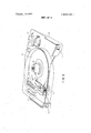
- FIGS. 3 and 4 are a top view and a sectional side view of magnetic disc apparatus incorporating the apparatus of FIG. 1;
- FIGS. 5 and 6 are perspective top and bottom views of the apparatus of FIGS. 3 and 4 mounted on a subframe;
- FIG. 7 shows the apparatus of FIGS. 5 and 6 mounted on a console
- FIG. 8 shows a modification to the apparatus of FIGS. 5 and 6.
- the positioning apparatus of FIG. 1 comprises a rotatably mounted bifurcated arm 10, and an electromagnetic actuator 11 for rotating the arm.
- the arm has two non-magnetic aluminum limbs 12, 13 which are fixed to a member 14, which in turn is rotatably mounted on a shaft 15 by a bearing 16, the shaft being carried by a fixed non-magnetic support 17.
- the bearing supports the arm for planar rotation about its center of gravity.
- the limbs 12, 13 have lateral extensions 18, 19 each carrying an electromagnetic transducing head 20, 21 and as will be explained, these heads are movable by the actuator between different radii of a rotatable magnetic disc 22 shown diagrammatically in FIG.
- the heads 20, 21 always remain opposite the disc, and are designed and mounted so that when the disc is stationary, the heads contact the disc, whereas when the disc is rotating at its operational speed, the heads fly on air bearings formed by boundary layers of air immediately adjacent the disc.
- the extensions 18, 19 are resiliently flexible to allow variation ofthe spacing of the heads from the disc when the disc is rotated and the heads begin to fly on the air bearings.
- the actuator 11 is at the opposite end of the arm 10 to the heads 20, 21 and that the shaft 15 is intermediate the heads and the actuator.
- the actuator 11 comprises a hollow coil 23 carried by the arm 10 and located remote from the shaft 15 so that when the arm rotates, the entire coil performs a translational movement along an arcuate path, and a stator 24 which is a permanent magnet and which is connected to the support 17.
- the magnet is E-shaped, the free ends of the arms 26, 27, 28 of the E" being magnetic pole pieces 30, 31, 32 which define magnetic flux gaps 33, 34 therebetween.
- the pole pieces have flat pole faces 36, 37, 38 (FIG. 2C) which face toward each other, and the coil 23 has a rectangular former 40, two opposite sides 41, 42 of which extend parallel to the pole faces 36, 37, 38.
- the pole piece 31 extends inside the coil, and the pole pieces 30, 32 of opposite polarity to the pole piece 31 extend outside the coil.
- the dimension of the hollow interior of the former 40 between its sides 44, 45 is greater than the dimensions of the pole piece 31 in the same direction, to allow rotation of the arm and areaate movement of the coil in the flux gaps 33, 34.
- the heads 20, 21 are disposed further from the shaft 15 than the coil 23, so that when the arm rotates, the heads move a greater distance than the coil, and mechanical magnification of the movement of the coil is obtained.
- actuator signals are supplied to the coil 23 via a flexible twin cable to cause current to pass therethrough, so that the coil experiences a force which causes it to move and rotate the arm 10.
- the central arm 27 of the permanent magnet is dimensioned so that it extends outwardly from the leg of the E beyond the outer arms 26, 28 as shown in FIG. 2A, and the winding density of the coil is concentrated toward the outer axial ends 52, 53 thereof (FIG. 28).
- FIGS. 3 and 4 are views of magnetic disc apparatus constituted by a module incorporating the positioning apparatus of FIGS. 1, 2A, 2B, and 2C, the expression module being used to denote a unit which is regarded for maintenance purposes as an exchangeable or replacement item.
- the concept of replacement subassemblies is already well-known in several industries, the sub-assembly being such that when it requires maintenance, it is replaced by a new or factoryreconditioned sub-assembly, any maintenance required not being undertaken on customers premises but being done, if at all, under precisely controlled conditions on the manufacturer's premises.
- the arrangement is such as to prevent ready access to the internal components of the module.
- the module has a single rotatable magnetic disc 22 (its position being indicated in dash line in FIG. 3), and the positioning apparatus (not shown in FIG. 4) is operable to move the heads 20, 21 between different radii of the disc and on opposite faces thereof for the heads to occupy different transducing positions relative to the disc.
- the positioning apparatus (not shown in FIG. 4) is operable to move the heads 20, 21 between different radii of the disc and on opposite faces thereof for the heads to occupy different transducing positions relative to the disc.
- the heads move inwardly of the disc, the limbs 12, 13 of the arms move increasingly over the opposite faces of the disc. Over the working range of move ment of the arm, the heads move along an are which is nearly a radial line of the disc.
- the disc, the arm 10 with the heads 20, 21 and the electromagnetic actuator 11 are contained together in hollow enclosing means comprising a base casting 55, a base flange 56, and a cover 57.
- the base flange 56 is permanently connected to the base coating 55 by a suitable adhesive such as an epoxy resin adhesive so that the connection between them is airtight.
- a destructible seal 59 which can for example be a thermoplastic adhesive which softens on heating.
- the base casting 55 rotatably supports a disc spindle 61 by bearings 62, 63, the spindle extending to the exterior of the enclosing means whereit is provided with coupling means in the form of a pulley wheel 64 whereby the disc can be driven from the exterior of the enclosing means.
- a labyrinth seal 65 is arranged between the base casting and the pulley.
- the base casting is provided with an aperture 67 covered by an air filter 68 which prevents dust particles entering the interior of the enclosing means.
- Aperture 67 and labyrinth seal 65 are the only paths for air to enter the interior of the enclosing means from the exterior, and the filter 68 and seal 65 effectively prevent the entry of dust particles into the interior of the enclosing means.
- the enclosing means is designed to maintain a substantially particle-free atmosphere therein constantly throughout the operational life of the enclosing means and its contents considered as a unit, during which time the disc 22, the arm 10 with its head 20, 21 and the electromagnetic actuator 11 remain continuously in said atmosphere in the enclosing means.
- the enclosing means is initially provided with such atmosphere during assembly by ensuring that all the components are dust free, and by assembling them together in a clean-air" room where stringent precautions are taken to eliminate and prevent entry of dust particles, the air in the room being constantly filtered and cleaned.
- the heads 20, 21 and the electromagnetic actuator 11 are electrically connected by conductors 70 (only two of which are shown in FIG. 4) to terminal 71 of two signal communication means in the form of couplings 73, 74, which make airtight seals with the base flange 56 and which have printed circuit card connectors 75 on the exterior of the enclosing means to which the terminals 71 are connected, whereby ready electrical connection can be made to the heads and the actuator 11, and head signals and actuator signals can be communicated between the exterior and interior of the enclosing means.
- the disc 22 is mounted on a hub 80 by a clamping ring 81, and the hub is fixed to the spindle 61, the hub being generally bell-shaped and bounding an annular region 82 between itself and a cylindrical section 83 of the base casting 55 which houses the bearing 63.
- the pressure in region 82 When the disc is rotated in operation, there is a tendancy for the pressure in region 82 to become sub-atmospheric, so that air tends to be drawn past the seal 65 and bearings 62, 63 into the interior ofthe enclosing means.
- the air might carry contaminants, e.g.
- the aperture 67 and filter 68 provide filtered air flow communication between the exterior of the enclosing means and the region 82.
- This region 82 is in the neighborhood of that one end of the bearing 63 which is innermost of the enclosing means, so that the air pressure neighboring that one end of the bearing 63 remains in operation substantially the same as the air pressure outside the enclosing means.
- the base casting 55 carries a support 90 which supports two fixed electromagnetic transducing heads 92, 93 for cooperation in transducing relationship with the side of the disc facing the base flange 56.
- the disc is driven unidirectionally in an anticlockwise sense having reference to FIG. 3.
- the arm l0and the actuator 11 are so arranged that the arm, in the direction from the actuator to the heads 20, 21 extends generally opposite to the direction of rotation of the disc past the heads 20, 21.
- the arm 10 is designed and arranged so that when the disc is rotated, substantially no resultant aerodynamic force arising due to air being swept off the disc because of its rotation acts on the arm tending to rotate it about shaft 15.
- the shaft 15 is disposed close to the periphery of the disc
- the limbs 12, 13 of the arm are substantially symmetrical about center line 96, shown in FIG. 3, and in the position of the arm shown where the heads 20, 21 are located at about the center tracks of the disc, the center line 96 extends in approximately the same direction as the direction of resultant air velocity affecting and passing the limbs 12, 13.
- FIGS. 5 and 6 show the module of FIGS. 3 and 4 mounted on a sub-frame 100.
- the sub-frame carries a unidirectional electric motor 101 which is coupled by a pulley wheel .102 on the motor shaft and an endless belt 103 to the pulley wheel 64.
- the motor 101 is mounted so that the belt is maintained under appropriate tension.
- the sub-frame has an aperture 105 through which the pulley wheel 64, filter 68 and part of the base casting 55 extend, and an aperture 106 and a cutaway portion 107 by which the printed circuit card connectors 75 are accessible.
- FIG. 7 shows the apparatus of FIGS. 5 and 6 mounted in a recess in a console housing 108.
- the module is mounted on the sub-frame 100, by any conventional means (not shown).
- the subframe is in turn mounted by means of shock and vibration absorbing mountings 110 (see FIGS. 5 and 6) so that the cover 57 of the module faces inwardly of the housing behind the sub-frame.
- shock and vibration absorbing mountings 110 see FIGS. 5 and 6
- the housing 108 contains actuator signal generating means 112 connected by leads not shown to deliver actuator signals via the printed circuit card connectors 75 to the electromagnetic actuator 11, and head signal circuitry 113 connected by leads not shown to deliver and/or receive head signals via the connectors 75 to and/or from the heads 20, 21.
- actuator signal generating means and head signal circuitry are well-known and will not be described in detail.
- the actuator signal generating means is responsive to disc track addresses supplied thereto to move the heads 20, 21 over said addressed tracks. In the particular embodiment illustrated.
- head 20 is an electromagnetic servotrack sensing head for sensing servo tracks records on one side of the disc
- head 21 is a read/write head for reading and writing data in concentric data tracks on the opposite side of the disc, there being one data track for each servo track.
- the actuator signal generating means 112 includes servo control means for controlling movement of the arm 10 so that when the arm has been moved to cause the head 21 to access an addressed data track, the head 21 is caused to follow that track by signals generated in the head 20 by the servo track associated with the addressed data track, the signals in head 20 indicating any offsetting of the head 20 from the center line of the servo track which it is sensing.
- FIG. 8 illustrates a modification to the apparatus of FIGS. 3, 4, and 6.
- a base casting 55' of the module supports a disc spindle 61 in a bearing 62', the spindle 61 having a friction disc 120 fixed to its end.
- a subframe 100 has three equally angularly spaced actuable clamps 121 (only one of which is shown in FIG. 8) which are engageable in recesses 122 in the base casting 55' to draw the module toward the subframe 100' so that the disc 120 engages a friction disc 123 connected to a shaft 124 which is rotatable in bearings 125 supported by the subframe 100', the other end of the shaft carrying a pulley wheel 64' driven by endless belt 103'.
- connection between the friction disc 123 and shaft 124 is by means of a symmetrical arrangement of rubber and spring connections 126, 127 (only three of which are shown) which are compressed when the clamps 121 are actuated.
- the discs 120, 123 constitute two clutch elements, the disc 123 being resiliently displaceable laterally to allow non-coaxial driving engagement between the discs as shown in FIG. 8, the axis of disc spindle 61' being shown at 128 and the axis of shaft 124 being shown at 129.
- the arm may be mounted on, or more accurately cantilevered from, a leaf spring support, instead of being mounted via shaft and bearing 16, so that operation of the actuator 11 causes the arm to perform a composite rotational and translational movement.
- a leaf spring support instead of being mounted via shaft and bearing 16
- such movement can be regarded as a rotation about shaft 15 and a movement of the shaft parallel to itself, so that with such a mounting, it is more accurate to say that the arm 10 is mounted for angular movement.
- the stator 24 can be an electromagnet instead of a permanent magnet.
- stator 24 can be U-shaped rather than 5"- shaped, one leg of the U extending inside and the other leg of the U" extending outside the coil 23, but this arrangement is as effective as the one described.
- the heads 20, 21 need not necessarily be flying heads.
- further fixed" heads can be provided.
- the actuator 11 can be located between the shaft 15 and heads 20, 21, so that heads move in the same direction as the coil 23.
- the module which has been described, essentially it is sealed in the sense that dust particles cannot enter it. Also, it is sealed in the sense that it prevents ready access to the contents of the module, namely, the disc, the arm and the actuator.
- Many other means apart from adhesives can be used to prevent ready access to the interior of the module, e.g., the components of the module can be interconnected by rivets, or by means including a tag seal which has to be severed before the components can be separated or by screws the heads of which are covered by material which has to be removed before the screws can be released.
- band seals of the kind which have a tag which normally engages a slot in the other end of the band to hold the band taut, release or severance of the tag allowing the band to be released.
- FIGS. 3 and 4 can be used as a replaceable disc pack for a disc file, i.e., when it is desired to use a further disc pack without discarding the one already on the file, the one on the file is detached and the further disc pack is put in its place.
- Positioning apparatus is not exclusively applicable to adjusting electromagnetic recording and/0r reproducing heads over a rotatable magnetic disc.
- any lightweight device to be positioned can be carried by the arm, e.g., a pen inscriber for recording a visual image of an analogue signal applied to the coil 23 on a moving paper strip.
- a random access disc memory system comprising:
- each said module being characterized by an enclosing means enclosing:
- said enclosing means having, and being designed to maintain, a substantially particle-free atmosphere therein constantly throughout the operational life of said enclosing means and its contents considered as a unit, during which time said disc, said arm with said head, and electromagnetic actuator remain continuously in said atmosphere in said enclosing means, said disc having coupling means associated therewith whereby the disc can be driven to rotate from the exterior of said enclosing means and said head and said electromagnetic actuator being operatively associated with signal communication means whereby head signals and actuator signals can be communicated between the exterior and interior of said enclosing means.
- a random access disc memory system as set forth in claim 2 in which said disc is rotatably mounted via a spindle supported by bearing means carried by said enclosing means, said spindle extending to the exterior of said enclosing means.
- a random access disc memory system as setforth in claim 2 wherein, said enclosing means being mounted on a sub-frame. which in turn is mounted on said housing such that removal of said enclosing means from said housing requires the sub-frame and enclosing means first to be removed as a unit from said housing.
- a random access disc memory system as set forth in claim 2 further including servo-control means, for controlling movement of said arm so that said heads follow any addressed one of a plurality of concentric tracks on said discs, said servo-control means including within each said disc module servo-tracks recorded on one of said disc and an electromagnetic servo-track sensing head carried by said arm.
- An interchangeable disc module as set forth in claim 11 wherein said section of said arm carries said magnetic transducers to be positioned.
- pole pieces have flat pole faces which face towards each other and said coil has a rectangular former, said former having two opposite sides of which extend parallel to said flat pole faces.
- An interchangeable disc module for use with any one of a plurality of like disc drives, said module having a first set of interfaces adapted to coact with a second set of interfaces on each of said drives, said module comprising in combination;
- a spindle assembly mounted in said base casting and having a first portion extending into said enclosing means and a second portion extending out of said enclosing means, said second portion being the first mechanical interface of said first set of interfaces;
- At least one magnetic disc mounted on said first portion of said spindle for rotation with said spindle;
- transducing means including at least one magnetic transducer located within said enclosing means;
- a motor within said enclosing means connected to said transducing means solely for selectively posisaid first set of interfaces
- said first mechanical and said first and said second electrical interfaces of said first set of interfaces being in a constant fixed space relationship to each other and located in the same position in all disc modules of this type, so that disc modules will be interchangeable among a plurality of like disc drives allowing data recorded on one disc module when coacting with a first one of said disc drives to be effectively read when said data module is coacting with the same or any second one of said disc drives.
Landscapes
- Engineering & Computer Science (AREA)
- Physics & Mathematics (AREA)
- Chemical & Material Sciences (AREA)
- Combustion & Propulsion (AREA)
- Electromagnetism (AREA)
- Power Engineering (AREA)
- Moving Of Heads (AREA)
- Holding Or Fastening Of Disk On Rotational Shaft (AREA)
- Printers Or Recording Devices Using Electromagnetic And Radiation Means (AREA)
- Electronic Switches (AREA)
Applications Claiming Priority (1)
| Application Number | Priority Date | Filing Date | Title |
|---|---|---|---|
| GB681771 | 1971-03-13 |
Publications (1)
| Publication Number | Publication Date |
|---|---|
| US3849800A true US3849800A (en) | 1974-11-19 |
Family
ID=9821301
Family Applications (1)
| Application Number | Title | Priority Date | Filing Date |
|---|---|---|---|
| US00231320A Expired - Lifetime US3849800A (en) | 1971-03-13 | 1972-03-02 | Magnetic disc apparatus |
Country Status (17)
| Country | Link |
|---|---|
| US (1) | US3849800A (pt) |
| JP (1) | JPS5640907B1 (pt) |
| AU (1) | AU465046B2 (pt) |
| BE (1) | BE780523A (pt) |
| BR (1) | BR7201420D0 (pt) |
| CA (1) | CA1012640A (pt) |
| CH (1) | CH533348A (pt) |
| DE (1) | DE2209522C3 (pt) |
| DK (1) | DK136557B (pt) |
| ES (1) | ES400501A1 (pt) |
| FI (1) | FI62428C (pt) |
| FR (1) | FR2129390A5 (pt) |
| GB (1) | GB1342495A (pt) |
| IT (1) | IT950054B (pt) |
| NL (1) | NL166566C (pt) |
| NO (1) | NO140574C (pt) |
| SE (1) | SE382513B (pt) |
Cited By (43)
| Publication number | Priority date | Publication date | Assignee | Title |
|---|---|---|---|---|
| US4034411A (en) * | 1975-07-11 | 1977-07-05 | International Business Machines Corporation | Magnetic disk information storage apparatus |
| US4054931A (en) * | 1975-04-02 | 1977-10-18 | International Business Machines Corporation | Gas filtering arrangement for magnetic disk information storage apparatus |
| US4092687A (en) * | 1976-09-07 | 1978-05-30 | Sycor, Inc. | Disc file assembly |
| US4145725A (en) * | 1976-12-20 | 1979-03-20 | International Business Machines Corporation | Electromagnetic actuator |
| US4185308A (en) * | 1976-09-24 | 1980-01-22 | Tokyo Shibaura Electric Co., Ltd. | Enclosed-type magnetic disc recording and/or reproducing apparatus |
| US4196456A (en) * | 1977-05-23 | 1980-04-01 | Basf Aktiengesellschaft | Magnetic head pivotal support with compact drive means |
| FR2448765A1 (fr) * | 1979-02-10 | 1980-09-05 | Computer Peripherie Tech | Memoire a disque magnetique |
| DE3010236A1 (de) * | 1979-03-20 | 1980-09-25 | Fujitsu Ltd | Magnetplattenspeicher |
| EP0020177A1 (en) * | 1979-06-04 | 1980-12-10 | Microcomputer Systems Corp. | Fixed disc head actuator assembly |
| JPS56159879A (en) * | 1980-04-11 | 1981-12-09 | Shiyugaato Tekunorojii | Hard disk driving device with air cleaner |
| EP0069545A2 (en) * | 1981-07-02 | 1983-01-12 | Irwin International, Inc. | Disc recorder with integral cartridge tape module |
| US4370687A (en) * | 1978-03-09 | 1983-01-25 | Tokyo Shibaura Denki Kabushiki Kaisha | Magnetic disk apparatus |
| EP0074131A1 (en) * | 1981-08-26 | 1983-03-16 | Koninklijke Philips Electronics N.V. | Swinging-arm device for an optical scanning unit |
| US4393425A (en) * | 1981-03-30 | 1983-07-12 | Disctron, Inc. | Linear head actuator |
| EP0152572A1 (de) * | 1984-02-07 | 1985-08-28 | Siemens Aktiengesellschaft | Positioniereinrichtung für einen Magnetplattenspeicher |
| US4587645A (en) * | 1984-05-07 | 1986-05-06 | Miniscribe Corporation | Disc drive assembly |
| EP0186380A2 (en) * | 1984-12-28 | 1986-07-02 | International Business Machines Corporation | An hermetically sealed disk file |
| FR2593318A1 (fr) * | 1986-01-21 | 1987-07-24 | Raymond Engineering | Organe de memoire a disque magnetique |
| US4692828A (en) * | 1984-07-31 | 1987-09-08 | Teac Corporation | Magnetic disk drive capable of mechanical connection to a data processing instrument without deformation |
| US4725904A (en) * | 1981-10-05 | 1988-02-16 | Tandon Corporation | Magnetic disk memory apparatus with improved contamination control |
| US4812932A (en) * | 1986-07-09 | 1989-03-14 | Hitachi, Ltd. | Vibration proof supporting structure for disk-type information memory unit |
| US4831476A (en) * | 1985-07-15 | 1989-05-16 | Allen-Bradley Company | Disc drive isolation system |
| US4833554A (en) * | 1987-02-25 | 1989-05-23 | Tandon Corporation | Hard disk drive module and receptacle therefor |
| US4864443A (en) * | 1987-11-02 | 1989-09-05 | Seagate Technology, Inc. | Disc clamping device |
| US4890174A (en) * | 1986-04-23 | 1989-12-26 | Rodime Plc | Rotary voice coil micro-hard disk drive system |
| US4920434A (en) * | 1980-09-24 | 1990-04-24 | Quantum Corporation | Fixed disk drive |
| US4982296A (en) * | 1980-09-24 | 1991-01-01 | Quantum Corporation | Head and disk assembly for fixed disk drive |
| US5119254A (en) * | 1980-09-24 | 1992-06-02 | Quantum Corporation | Data transducer position control system for rotating disk data storage equipment |
| US5304878A (en) * | 1990-11-29 | 1994-04-19 | Mitsubishi Denki Kabushiki Kaisha | Electronic parts and connector mounting structure of disk unit |
| US5396384A (en) * | 1992-05-12 | 1995-03-07 | Quantum Corporation | Hard disk drive architecture |
| US5454158A (en) * | 1993-01-08 | 1995-10-03 | International Business Machines Corporation | Method of making integral transducer-suspension assemblies for longitudinal recording |
| US5486963A (en) * | 1992-08-19 | 1996-01-23 | International Business Machines Corporation | Integrated transducer-suspension structure for longitudinal recording |
| US5559652A (en) * | 1993-08-23 | 1996-09-24 | Heath; John S. | Disk drive rotary actuator with rocking pivot |
| US5708539A (en) * | 1980-03-05 | 1998-01-13 | Papst Licensing Gmbh & Co. Kg | Disk storage drive |
| US5745979A (en) * | 1992-08-25 | 1998-05-05 | International Business Machines Corporation | Magnetic head for recording with ultra low force |
| US5870264A (en) * | 1993-09-06 | 1999-02-09 | Restle; Wilfried | Method and arrangement for significantly increasing the lifetime of magnetic disk storage devices |
| US6519110B2 (en) | 1988-01-25 | 2003-02-11 | Seagate Technologies Llc | Disk drive pass-through connector |
| USRE38179E1 (en) | 1980-05-10 | 2003-07-08 | Papst Licensing Gmbh & Co. Kg | Disk storage device having a three-phase brushless DC underhub configured spindle motor |
| USRE38601E1 (en) | 1980-05-10 | 2004-09-28 | Papst Licensing, GmbH & Co. KG | Disk storage device having a radial magnetic yoke feature |
| USRE38662E1 (en) | 1980-05-10 | 2004-11-30 | Papst Licensing Gmbh & Co. Kg | Disk storage device having a sealed bearing tube |
| USRE38673E1 (en) | 1980-05-10 | 2004-12-21 | Papst Licensing Gmbh & Co. Kg | Disk storage device having a hub sealing member feature |
| US20050115057A1 (en) * | 2003-11-28 | 2005-06-02 | Tdk Corporation | Method of manufacturing a magnetic head, and magnetic head manufacturing apparatus |
| USRE38772E1 (en) | 1981-03-18 | 2005-08-09 | Papst Licensing Gmbh & Co. Kg | Disk storage device having an undercut hub member |
Families Citing this family (8)
| Publication number | Priority date | Publication date | Assignee | Title |
|---|---|---|---|---|
| JPS5635984Y2 (pt) * | 1976-09-24 | 1981-08-24 | ||
| NL7612401A (nl) * | 1976-11-09 | 1978-05-11 | Philips Nv | Elektrisch bestuurbare draagarminrichting. |
| US4346416A (en) * | 1980-02-29 | 1982-08-24 | Digital Equipment Corporation | Rotary actuator assembly for disk drive head positioner |
| NL8102523A (nl) * | 1981-05-22 | 1982-12-16 | Philips Nv | Zwenkarminrichting voor magneetschijfgeheugeninrichting. |
| DE3509111A1 (de) * | 1984-03-19 | 1985-09-19 | Hewlett-Packard Co., Palo Alto, Calif. | Positioniervorrichtung fuer den kopf einer plattenspeichereinrichtung |
| US4672488A (en) * | 1984-08-22 | 1987-06-09 | Wright Harold T | Spindle hub-disc interface |
| DE3601845A1 (de) * | 1985-01-25 | 1986-07-31 | Priam Corp., San Jose, Calif. | Zusammen mit einem magnetplattenantrieb einsetzbare schwenkbetaetigungsvorrichtung |
| CN109088136A (zh) * | 2018-09-20 | 2018-12-25 | 中国人民解放军63653部队 | 提高储能切换法微波脉冲压缩装置能量提取效率的方法 |
Citations (9)
| Publication number | Priority date | Publication date | Assignee | Title |
|---|---|---|---|---|
| US3412386A (en) * | 1964-09-01 | 1968-11-19 | Mohawk Data Sciences Corp | Random access positioning means for a magnetic disc file |
| US3449734A (en) * | 1965-04-28 | 1969-06-10 | Mohawk Data Sciences Corp | Positioning apparatus for a random access storage device using a dual-frequency reference track |
| US3478341A (en) * | 1966-07-11 | 1969-11-11 | Ncr Co | Random access magnetic disc storage device with peripheral bearing means |
| US3553663A (en) * | 1968-07-05 | 1971-01-05 | Ex Cell O Corp | Single disc file memory system |
| US3577133A (en) * | 1968-11-19 | 1971-05-04 | Engineered Data Peripherals Co | Disc memory system including unitary support member and printed circuit board |
| US3624624A (en) * | 1969-07-24 | 1971-11-30 | Sperry Rand Corp | Magnetic drum air filtration and purging system |
| US3631419A (en) * | 1970-04-10 | 1971-12-28 | Iomec | Apparatus for the vibration-free positioning of movable components |
| US3651501A (en) * | 1970-08-31 | 1972-03-21 | Singer Co | Transducer head actuator for magnetic disc memory |
| US3710357A (en) * | 1970-07-02 | 1973-01-09 | Ibm | Magnetic disk storage file in sealed enclosure |
-
1971
- 1971-03-13 GB GB681771*[A patent/GB1342495A/en not_active Expired
- 1971-08-26 AU AU32789/71A patent/AU465046B2/en not_active Expired
-
1972
- 1972-02-08 FR FR7204899A patent/FR2129390A5/fr not_active Expired
- 1972-02-08 SE SE7201465A patent/SE382513B/xx unknown
- 1972-02-18 FI FI447/72A patent/FI62428C/fi active
- 1972-02-29 DE DE2209522A patent/DE2209522C3/de not_active Expired
- 1972-03-01 NL NL7202655.A patent/NL166566C/xx not_active IP Right Cessation
- 1972-03-02 US US00231320A patent/US3849800A/en not_active Expired - Lifetime
- 1972-03-07 ES ES400501A patent/ES400501A1/es not_active Expired
- 1972-03-09 CA CA136,741A patent/CA1012640A/en not_active Expired
- 1972-03-09 CH CH347372A patent/CH533348A/de not_active IP Right Cessation
- 1972-03-10 IT IT21662/72A patent/IT950054B/it active
- 1972-03-10 JP JP2408272A patent/JPS5640907B1/ja active Pending
- 1972-03-10 NO NO783/72A patent/NO140574C/no unknown
- 1972-03-10 DK DK113072AA patent/DK136557B/da not_active IP Right Cessation
- 1972-03-10 BE BE780523A patent/BE780523A/xx not_active IP Right Cessation
- 1972-03-13 BR BR1420/72A patent/BR7201420D0/pt unknown
Patent Citations (9)
| Publication number | Priority date | Publication date | Assignee | Title |
|---|---|---|---|---|
| US3412386A (en) * | 1964-09-01 | 1968-11-19 | Mohawk Data Sciences Corp | Random access positioning means for a magnetic disc file |
| US3449734A (en) * | 1965-04-28 | 1969-06-10 | Mohawk Data Sciences Corp | Positioning apparatus for a random access storage device using a dual-frequency reference track |
| US3478341A (en) * | 1966-07-11 | 1969-11-11 | Ncr Co | Random access magnetic disc storage device with peripheral bearing means |
| US3553663A (en) * | 1968-07-05 | 1971-01-05 | Ex Cell O Corp | Single disc file memory system |
| US3577133A (en) * | 1968-11-19 | 1971-05-04 | Engineered Data Peripherals Co | Disc memory system including unitary support member and printed circuit board |
| US3624624A (en) * | 1969-07-24 | 1971-11-30 | Sperry Rand Corp | Magnetic drum air filtration and purging system |
| US3631419A (en) * | 1970-04-10 | 1971-12-28 | Iomec | Apparatus for the vibration-free positioning of movable components |
| US3710357A (en) * | 1970-07-02 | 1973-01-09 | Ibm | Magnetic disk storage file in sealed enclosure |
| US3651501A (en) * | 1970-08-31 | 1972-03-21 | Singer Co | Transducer head actuator for magnetic disc memory |
Cited By (56)
| Publication number | Priority date | Publication date | Assignee | Title |
|---|---|---|---|---|
| US4054931A (en) * | 1975-04-02 | 1977-10-18 | International Business Machines Corporation | Gas filtering arrangement for magnetic disk information storage apparatus |
| US4034411A (en) * | 1975-07-11 | 1977-07-05 | International Business Machines Corporation | Magnetic disk information storage apparatus |
| US4092687A (en) * | 1976-09-07 | 1978-05-30 | Sycor, Inc. | Disc file assembly |
| US4185308A (en) * | 1976-09-24 | 1980-01-22 | Tokyo Shibaura Electric Co., Ltd. | Enclosed-type magnetic disc recording and/or reproducing apparatus |
| US4292656A (en) * | 1976-09-24 | 1981-09-29 | Tokyo Shibaura Electric Co., Ltd. | Enclosed-type magnetic disc recording and/or reproducing apparatus |
| US4145725A (en) * | 1976-12-20 | 1979-03-20 | International Business Machines Corporation | Electromagnetic actuator |
| US4196456A (en) * | 1977-05-23 | 1980-04-01 | Basf Aktiengesellschaft | Magnetic head pivotal support with compact drive means |
| US4370687A (en) * | 1978-03-09 | 1983-01-25 | Tokyo Shibaura Denki Kabushiki Kaisha | Magnetic disk apparatus |
| FR2448765A1 (fr) * | 1979-02-10 | 1980-09-05 | Computer Peripherie Tech | Memoire a disque magnetique |
| DE3010236A1 (de) * | 1979-03-20 | 1980-09-25 | Fujitsu Ltd | Magnetplattenspeicher |
| EP0020177A1 (en) * | 1979-06-04 | 1980-12-10 | Microcomputer Systems Corp. | Fixed disc head actuator assembly |
| US4300176A (en) * | 1979-06-04 | 1981-11-10 | Microcomputer Systems Corp. | Fixed disc head actuator assembly |
| US5946161A (en) * | 1980-03-05 | 1999-08-31 | Papst Licensing Gmbh | Disk storage device having a labyrinth seal |
| US5777822A (en) * | 1980-03-05 | 1998-07-07 | Papst Licensing Gmbh | Disk storage drive |
| US5708539A (en) * | 1980-03-05 | 1998-01-13 | Papst Licensing Gmbh & Co. Kg | Disk storage drive |
| US5729403A (en) * | 1980-03-05 | 1998-03-17 | Papst Licensing Gmbh | Disk storage drive |
| JPS6059661B2 (ja) * | 1980-04-11 | 1985-12-26 | シユガ−ト テクノロジイ | 空気清浄装置つきハ−ドデイスク駆動装置 |
| JPS56159879A (en) * | 1980-04-11 | 1981-12-09 | Shiyugaato Tekunorojii | Hard disk driving device with air cleaner |
| USRE38601E1 (en) | 1980-05-10 | 2004-09-28 | Papst Licensing, GmbH & Co. KG | Disk storage device having a radial magnetic yoke feature |
| USRE38662E1 (en) | 1980-05-10 | 2004-11-30 | Papst Licensing Gmbh & Co. Kg | Disk storage device having a sealed bearing tube |
| USRE38673E1 (en) | 1980-05-10 | 2004-12-21 | Papst Licensing Gmbh & Co. Kg | Disk storage device having a hub sealing member feature |
| USRE38178E1 (en) | 1980-05-10 | 2003-07-08 | Papst Licensing Gmbh & Co. Kg | Disk storage device having an underhub spindle motor |
| USRE38179E1 (en) | 1980-05-10 | 2003-07-08 | Papst Licensing Gmbh & Co. Kg | Disk storage device having a three-phase brushless DC underhub configured spindle motor |
| US5119254A (en) * | 1980-09-24 | 1992-06-02 | Quantum Corporation | Data transducer position control system for rotating disk data storage equipment |
| US4982296A (en) * | 1980-09-24 | 1991-01-01 | Quantum Corporation | Head and disk assembly for fixed disk drive |
| US4920434A (en) * | 1980-09-24 | 1990-04-24 | Quantum Corporation | Fixed disk drive |
| USRE38772E1 (en) | 1981-03-18 | 2005-08-09 | Papst Licensing Gmbh & Co. Kg | Disk storage device having an undercut hub member |
| US4393425A (en) * | 1981-03-30 | 1983-07-12 | Disctron, Inc. | Linear head actuator |
| EP0069545A3 (en) * | 1981-07-02 | 1983-04-27 | Irwin International, Inc. | Disc recorder with integral cartridge tape module |
| EP0069545A2 (en) * | 1981-07-02 | 1983-01-12 | Irwin International, Inc. | Disc recorder with integral cartridge tape module |
| EP0074131A1 (en) * | 1981-08-26 | 1983-03-16 | Koninklijke Philips Electronics N.V. | Swinging-arm device for an optical scanning unit |
| US4725904A (en) * | 1981-10-05 | 1988-02-16 | Tandon Corporation | Magnetic disk memory apparatus with improved contamination control |
| US4689703A (en) * | 1984-02-07 | 1987-08-25 | Siemens Aktiengesellschaft | Positioning device for a magnetic disk memory |
| EP0152572A1 (de) * | 1984-02-07 | 1985-08-28 | Siemens Aktiengesellschaft | Positioniereinrichtung für einen Magnetplattenspeicher |
| US4587645A (en) * | 1984-05-07 | 1986-05-06 | Miniscribe Corporation | Disc drive assembly |
| US4692828A (en) * | 1984-07-31 | 1987-09-08 | Teac Corporation | Magnetic disk drive capable of mechanical connection to a data processing instrument without deformation |
| EP0186380A2 (en) * | 1984-12-28 | 1986-07-02 | International Business Machines Corporation | An hermetically sealed disk file |
| EP0186380A3 (en) * | 1984-12-28 | 1987-09-09 | International Business Machines Corporation | An hermetically sealed disk file |
| US4831476A (en) * | 1985-07-15 | 1989-05-16 | Allen-Bradley Company | Disc drive isolation system |
| FR2593318A1 (fr) * | 1986-01-21 | 1987-07-24 | Raymond Engineering | Organe de memoire a disque magnetique |
| US4890174A (en) * | 1986-04-23 | 1989-12-26 | Rodime Plc | Rotary voice coil micro-hard disk drive system |
| US4812932A (en) * | 1986-07-09 | 1989-03-14 | Hitachi, Ltd. | Vibration proof supporting structure for disk-type information memory unit |
| US4833554A (en) * | 1987-02-25 | 1989-05-23 | Tandon Corporation | Hard disk drive module and receptacle therefor |
| US4864443A (en) * | 1987-11-02 | 1989-09-05 | Seagate Technology, Inc. | Disc clamping device |
| US6519110B2 (en) | 1988-01-25 | 2003-02-11 | Seagate Technologies Llc | Disk drive pass-through connector |
| US5304878A (en) * | 1990-11-29 | 1994-04-19 | Mitsubishi Denki Kabushiki Kaisha | Electronic parts and connector mounting structure of disk unit |
| US5396384A (en) * | 1992-05-12 | 1995-03-07 | Quantum Corporation | Hard disk drive architecture |
| US5655286A (en) * | 1992-08-19 | 1997-08-12 | International Business Machines Corporation | Integrated transducer-suspension structure for longitudinal recording |
| US5486963A (en) * | 1992-08-19 | 1996-01-23 | International Business Machines Corporation | Integrated transducer-suspension structure for longitudinal recording |
| US5742998A (en) * | 1992-08-19 | 1998-04-28 | International Business Machines Corporation | Method of making integrated suspension magnetic head structures for longitudinal recording |
| US6271995B1 (en) | 1992-08-25 | 2001-08-07 | International Business Machines Corporation | Magnetic head for recording with ultra low force |
| US5745979A (en) * | 1992-08-25 | 1998-05-05 | International Business Machines Corporation | Magnetic head for recording with ultra low force |
| US5454158A (en) * | 1993-01-08 | 1995-10-03 | International Business Machines Corporation | Method of making integral transducer-suspension assemblies for longitudinal recording |
| US5559652A (en) * | 1993-08-23 | 1996-09-24 | Heath; John S. | Disk drive rotary actuator with rocking pivot |
| US5870264A (en) * | 1993-09-06 | 1999-02-09 | Restle; Wilfried | Method and arrangement for significantly increasing the lifetime of magnetic disk storage devices |
| US20050115057A1 (en) * | 2003-11-28 | 2005-06-02 | Tdk Corporation | Method of manufacturing a magnetic head, and magnetic head manufacturing apparatus |
Also Published As
| Publication number | Publication date |
|---|---|
| ES400501A1 (es) | 1975-07-16 |
| IT950054B (it) | 1973-06-20 |
| DK136557B (da) | 1977-10-24 |
| DE2209522C3 (de) | 1979-10-04 |
| FI62428B (fi) | 1982-08-31 |
| CH533348A (de) | 1973-01-31 |
| SE382513B (sv) | 1976-02-02 |
| AU465046B2 (en) | 1975-09-18 |
| CA1012640A (en) | 1977-06-21 |
| FI62428C (fi) | 1982-12-10 |
| BR7201420D0 (pt) | 1973-06-14 |
| NO140574C (no) | 1979-09-26 |
| FR2129390A5 (pt) | 1972-10-27 |
| NO140574B (no) | 1979-06-18 |
| NL7202655A (pt) | 1972-09-15 |
| BE780523A (fr) | 1972-09-11 |
| DE2209522B2 (de) | 1976-02-12 |
| DE2209522A1 (de) | 1972-09-28 |
| DK136557C (pt) | 1978-03-20 |
| JPS5640907B1 (pt) | 1981-09-24 |
| AU3278971A (en) | 1973-03-01 |
| GB1342495A (en) | 1974-01-03 |
| NL166566C (nl) | 1981-08-17 |
Similar Documents
| Publication | Publication Date | Title |
|---|---|---|
| US3849800A (en) | Magnetic disc apparatus | |
| EP0490069B1 (en) | Magnetic disk drive | |
| US4062049A (en) | Integrated Disk File Module and memory storage system | |
| US5455728A (en) | Disk drive employing compact magnetic actuator latch mechanism | |
| US4150406A (en) | Transducer lifting means employing plural flexures | |
| EP0006631B1 (en) | Disk storage apparatus | |
| US4331991A (en) | Head actuator for magnetic disk drive | |
| US3710357A (en) | Magnetic disk storage file in sealed enclosure | |
| US6252744B1 (en) | Voice-coil integrated non-contacting magnetic latch for a disc drive actuator assembly | |
| EP0014231B1 (en) | Information storage apparatus | |
| CA1120149A (en) | Rigid magnetic disc memory apparatus employing stepper motor drive and pivotable head support | |
| US5523912A (en) | Magnetic head positioner for magnetic disk apparatus which can prevent mechanical shock | |
| US4058844A (en) | Low-mass short-stroke voice-coil actuator for integrated disk file module | |
| EP0704090A4 (en) | NON-CONTACT MAGNETIC PASSIVE LOCK | |
| JPH04263187A (ja) | ディスク型記録装置およびその組立方法 | |
| JP3375259B2 (ja) | 磁気ディスク装置 | |
| JP2753220B2 (ja) | 情報記録再生装置 | |
| JP3688445B2 (ja) | 磁気ディスク装置 | |
| JPH02240889A (ja) | 磁気ディスク装置のスピンドル組立て構造 | |
| JP2752830B2 (ja) | 磁気ディスク装置 | |
| JPH02148463A (ja) | 磁性流体封止形カートリッジ式磁気ディスク装置 | |
| US6310413B1 (en) | Steering magnets to reduce magnetic leakage flux in a disk drive | |
| JPH03144978A (ja) | 磁気ディスク装置 | |
| JP2656261B2 (ja) | 磁気ディスク装置 | |
| JPH02126485A (ja) | カートリッジ式磁気ディスク装置 |