US3844193A - Clarinet - Google Patents
Clarinet Download PDFInfo
- Publication number
- US3844193A US3844193A US00427013A US42701373A US3844193A US 3844193 A US3844193 A US 3844193A US 00427013 A US00427013 A US 00427013A US 42701373 A US42701373 A US 42701373A US 3844193 A US3844193 A US 3844193A
- Authority
- US
- United States
- Prior art keywords
- clarinet
- stop valve
- air outlet
- key
- barrel
- Prior art date
- Legal status (The legal status is an assumption and is not a legal conclusion. Google has not performed a legal analysis and makes no representation as to the accuracy of the status listed.)
- Expired - Lifetime
Links
Images


Classifications
-
- G—PHYSICS
- G10—MUSICAL INSTRUMENTS; ACOUSTICS
- G10D—STRINGED MUSICAL INSTRUMENTS; WIND MUSICAL INSTRUMENTS; ACCORDIONS OR CONCERTINAS; PERCUSSION MUSICAL INSTRUMENTS; AEOLIAN HARPS; SINGING-FLAME MUSICAL INSTRUMENTS; MUSICAL INSTRUMENTS NOT OTHERWISE PROVIDED FOR
- G10D7/00—General design of wind musical instruments
- G10D7/06—Beating-reed wind instruments, e.g. single or double reed wind instruments
- G10D7/066—Clarinets
Definitions
- this invention permits not only of widening the clarinet register but also of hearing notes considerably above the usual musical range, and in any case practically not feasible with the present clarinets of the BOEHM or HOELLER system.
- the clarinet according tothis invention is h cterized .in haiitsJLEUEEQE BEEQHKQE I I holes or passages of different cross-sections, adapted to produce the fifth harmonic sounds or seventeenths notes of the fundamental sounds of the clarinet, corrected to comply with the tempered chord, with the assistance of a pair of stop valve keys permitting of selectively opening or uncovering these two air outlets, the existing so-called twelfth key being opened simultaneously.
- these two additional air passages are so located that their upper edges are substantially flush with that of the shoulder limiting the penetration of the clarinet mouthpiece into the instrument tube or upper body.
- the diameter of the major air outlet passage uncovered-by one of the keys for producing the low seventeenths ranges from 4.5 to 6 mm
- the diameter of the minor air outlet passage uncovered by the other key for producing the upper seventeenths ranges from 1.5 to 3 mm.
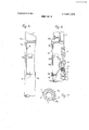
- FIGS. land 2 are twoelevational views, taken perpendicularly to each other, of the upper tube of a clarinet with the keys associated therewith;
- FIGS. 3 and 4 are two elevational views, taken perpendicularly to each other, of the upper tube or body and of the barrel of a clarinet with the means for actuating one of the keys according to this invention;
- FIGS. 5 and 6 are two elevational views, taken perpendicularly to each other, of the lower body or tube of the clarinet, and
- FIG. 7 is a cross-section taken along the line VII-VII of FIG. 3.
- FIGS. 1 to 4 The clarinet illustrated in FIGS. 1 to 4 is partially illustrated by showing its upper body or tube 1 on which the barrel 2 is mounted in the conventional manner.
- the corresponding air outlet is controlled by means of a pair of keys 6, 7 carrying corresponding superposed stop valves 8, 9, respectively, so disposed that stop valve 9 engages directly the edge of said hole 4, and comprises in its portion nearest to the shoulder 3 a passage 9a of smaller size than said hole 4 and normally closed by the other stop valve 8.
- the key 7 co-acts with a rocker 10 supporting the stop valve 9.
- This key 7 pivoted to the barrel by means of a pin 11 is responsive to a spring (not visible in the drawing) urging said key against the rocker 10 with a force greater than that of another spring (also not shown in the drawings) urging the rocker 10 itself in the direction to open said'stop valve 9.
- the key 6 fulcrumed to the barrelby means of a pin 12 is responsive to another spring 13 normally holding the stop valve 8 in engagement with stop valve 9 and also stronger than the spring urging stop valve 9 to its open position, for a reason to be explained presently.
- the key 6 is controlled by means mounted to said upper clarinet body 1 and comprising a lever 15 having its finger-actuated portion 15a located in close vicinity of the existing twelfth key 16.
- the lever 15 is fulcrumed to a pivot pin 15b and its armlSc constitutes the control member of the aforesaid twelfth key 16 of which the stop valve 17 is lifted or unseated when the control member 15a is depressed.
- the arm 15c co-acts with the end of an arcuate lever 18 fulcrumed at 19 and engaging with its other end the key 6, so that the stop valve 8 is urged to its open position with said control member 15a is depressed.
- the firstfour seventeenths of-this stave correspond to one portion of the-fundamental .sounds that can be will nevertheless hold the two stop valves 8 and 9 in their closed or seated positions due to the aforementioned preponderance of the force of its spring over the sounds that can be obtained by using the lower half of the clarinet body are also obtainable by using the same fingering as for these fundamental sounds.
- the pivot pin of this ring 20 carries a lug or arm 20a co-acting with linkage means so arranged that stop valve 9 is open when ring 20 is depressed, this action being obtained through the lowing means.
- the lug'20a engages with its free end one end of a rocker 25 engaging in turn with its other end a lug 26a of a lever 26 pivotally mounted by means of its shaft or pivot pin 26b to the lower clarinet body, this lever 26 comprising another lug 26c engaging a lug 270 formed on a lever 27 pivotally mounted to the upper clarinet body 1 by means of its shaft or pivot pin 27b (see FIG. 4), this lever 27 carrying at its upper portion a lug or arm 27c partially surrounding the upper clarinet body so asto engage with its free end the key 7, as shown in FIG. 7.
- the means contemplated according to the present invention enable the clarinettist of emitting the seventeenths of the fundamental sounds obtainable from the lower body or tube of the clarinet, with the same fingering as that necessary for producing these fundamental sounds, plus the actuation of the mechanism according to this invention, as set forth hereinabove, thus simplify considerably his task and enabling him to attain a higher degree of virtuosity.
- This improvement is applicable to all existing clarinets, of the BOEHM or HOELLER system, and particularly to the simple or Albert E-flat clarinet, the C clarinet, the B-flat clarinet, the A-clarinet, the altoclarinet or basset horn, the tenor clarinet and F clarinet, the bass clarinet (modern the contrabass clarinet, double-bass clarinet or pedal clarinet, the Denner clarinet, etc.., by simply adapting the dimensions of the superposed major and minor holes, for all these instruments have different lengths and cross-sectional dimen sions.
- Clarinet comprising a lower body and an upper body, a barrel, and a mouthpiece fitted in said barrel,
- h actsnzs n that itg mpr sl s in saidha irq a Pair of air'outletpassages having different cross-sectional passage areas, adapted-to produce the fifth harmonic sounds or the seventeenths of the fundamental sounds of the clarinet, and two keys carrying stop valves for selectively opening said air outlet passages, the existing so-called key of twelfth being actuated simultaneously to its open position.
- said barrel comprises a shoulder engaged by said mouthpiece in its innerrn9s t 9 r a l1l 1tin g position, and is characterized in that the two air outlet passages are so disposed as to have their upper edges substantially flush with the level of said mouthpiece abutment shoulder.
- said one stop valve associated with said major air outlet passage is carried by a rocker urged by first spring means to its open position, the control key of said one stop valve being urged against said rocker by other spring means having a force greater than that of said first spring means, another key, carrying the stop valve superposed to said one stop valve, being also pressed against said one stop valve by a spring force greater than that of said first spring means.
- Clarinet according to claim 4 characterized in that the key controlling the stop valve associated with the major air outlet passage is actuated from the lower ring of the group of three ring keys normally provided on the lower clarinet body and adapted to be actuated by the instrumentalists right hand, said lower ring being rendered independent of the other two by unidirectional coupling means provided therebetween and such that said lower ring can actuate said other rings without being actuated thereby.
Abstract
Clarinet comprising a lower body and an upper body, a barrel, and a mouthpiece fitted in said barrel, characterized in that it comprises in said barrel a pair of air outlet passages having different cross-sectional passage areas, adapted to produce the fifth harmonic sounds or the seventeenths of the fundamental sounds of the clarinet, and two keys carrying stop valves for selectively opening said air outlet passages, the existing socalled key of twelfth being actuated simultaneously to its open position.
Description
United States Patent [11] 3,844,193 Marchi Oct. 29, 1974 [54] CLARINET FOREIGN PATENTS OR APPLICATIONS [76] Inventor: Joseph Marchi, 9 rue Romain 48,357
Rolland, Sete, France 1930 Norway 84/382 22 Filed; Dec. 3 7 Primary ExaminerStephen J. Tomsky Assistant Examiner-Vit W. Miska pp 427,013 Attorney, Agent, or Firm-Fleit, Gipple Jacobson [30] Foreign Application Priority Data ABSTRACT Dec. 20, 1972 France 72.45505 Clafinet Comprising a lower body and an pp body,
a barrel, and a mouthpiece fitted in said barrel, cha- 52 us. Cl. 84/382 raclefl'led in that it Comprises in said be"? 32%! of [51] Int. Cl G10v 7/06 air Outlet Passages having different Cross-Sectional P 58 Field of Search 84/382, 380, 383 Sage areas, adaPted to Produce the fifth harmonic sounds or the seventeenths of the fundamental sounds [56] Ref n i d of the clarinet, and two keys carrying stop valves for UNITED STATES PATENTS selectively opening said air outlet passages, the exist- 2 832 250 4/1958 Leblanc 84/382 ingso-called key of twelfth being actuated simulta- 219511412 9/1967 christen's'ii'I """YIIIIIIIIIIII 84/382 newly 3,526,165 9/1970 Robbins 84/382 7 Claims, 7 Drawing Figures 7 Y1[ 13 2 c m r T d a 17 u F 15 1a c 19 16 PATENTEDUCIZS 1914 18441193 saw 20F 3- PATENTEDUBI 29 I974 SHEET 3 OF 3 1 CLARINET The present invention relates in general to clarinets and has more particularly for its object improvements mental sounds emitted by this instrument, that is, the seventeenth notes above these fundamental sounds, by -forming in the clarinet barrel a hole adapted to be opened to this end by means of a key, these sounds being thus obtained by using a simpler fingering than the fingering now required for obtaining the same sounds.
This arrangement, based on the principle of the natural'resonance of the sound body or resonator, is however only partially satisfactory as far as the correctness of the sounds thus produced is concerned, considering the principle of the tempered chord governing musical intervals.
It is the essential object of the present invention to provide an improvement in clarinets with a view to obtain the aforesaid fifth harmonic sounds with an automatic correction of their pitch, that is, with a high degree of accuracy, these fifth harmonic sounds being obtained by using a particularly simple mechanism and very easily, thus affording a hitherto unnattainable degree of virtuosity.
At the same time, this invention permits not only of widening the clarinet register but also of hearing notes considerably above the usual musical range, and in any case practically not feasible with the present clarinets of the BOEHM or HOELLER system.
Basically, the clarinet according tothis invention is h cterized .in haiitsJLEUEEQE BEEQHKQE I I holes or passages of different cross-sections, adapted to produce the fifth harmonic sounds or seventeenths notes of the fundamental sounds of the clarinet, corrected to comply with the tempered chord, with the assistance of a pair of stop valve keys permitting of selectively opening or uncovering these two air outlets, the existing so-called twelfth key being opened simultaneously.
More particularly, these two additional air passages are so located that their upper edges are substantially flush with that of the shoulder limiting the penetration of the clarinet mouthpiece into the instrument tube or upper body.
More particularly, in the case of B flat and A clarinets, the diameter of the major air outlet passage uncovered-by one of the keys for producing the low seventeenths ranges from 4.5 to 6 mm, and the diameter of the minor air outlet passage uncovered by the other key for producing the upper seventeenths ranges from 1.5 to 3 mm.
A typical embodiment of an improved clarinet according to this invention will now be described by way of example with reference to the attached which:
FIGS. land 2 are twoelevational views, taken perpendicularly to each other, of the upper tube of a clarinet with the keys associated therewith;
FIGS. 3 and 4 are two elevational views, taken perpendicularly to each other, of the upper tube or body and of the barrel of a clarinet with the means for actuating one of the keys according to this invention;
drawings, in
FIGS. 5 and 6 are two elevational views, taken perpendicularly to each other, of the lower body or tube of the clarinet, and
FIG. 7 is a cross-section taken along the line VII-VII of FIG. 3.
The clarinet illustrated in FIGS. 1 to 4 is partially illustrated by showing its upper body or tube 1 on which the barrel 2 is mounted in the conventional manner.
In this barrel, at the level of the area where the note of the fifth harmonic sounds (or seventeenth note above the fundamental sound) is formed, there is provided below the level of the shoulder 3 limiting the penetration of the mounthpiece (not shown) a hole 4 having its upper edge substantially flush with said shoulder and adapted to receive (optionally) a bevelled airintercepting tubular element 5 having its inlet directed upwards, i.e., towards the mouthpiece-receiving end of the instrument. The corresponding air outlet is controlled by means of a pair of keys 6, 7 carrying corresponding superposed stop valves 8, 9, respectively, so disposed that stop valve 9 engages directly the edge of said hole 4, and comprises in its portion nearest to the shoulder 3 a passage 9a of smaller size than said hole 4 and normally closed by the other stop valve 8. The key 7 co-acts with a rocker 10 supporting the stop valve 9. This key 7 pivoted to the barrel by means of a pin 11 is responsive to a spring (not visible in the drawing) urging said key against the rocker 10 with a force greater than that of another spring (also not shown in the drawings) urging the rocker 10 itself in the direction to open said'stop valve 9. The key 6 fulcrumed to the barrelby means of a pin 12 is responsive to another spring 13 normally holding the stop valve 8 in engagement with stop valve 9 and also stronger than the spring urging stop valve 9 to its open position, for a reason to be explained presently.
As clearly shown in FIGS. 3 and 4, the key 6 is controlled by means mounted to said upper clarinet body 1 and comprising a lever 15 having its finger-actuated portion 15a located in close vicinity of the existing twelfth key 16. The lever 15 is fulcrumed to a pivot pin 15b and its armlSc constitutes the control member of the aforesaid twelfth key 16 of which the stop valve 17 is lifted or unseated when the control member 15a is depressed. Moreover, the arm 15c co-acts with the end of an arcuate lever 18 fulcrumed at 19 and engaging with its other end the key 6, so that the stop valve 8 is urged to its open position with said control member 15a is depressed. This simultaneous opening of stop valves 17 and 8, when playing the instrument, produces the seventeenths of the following fundamental sounds:
The firstfour seventeenths of-this stave:correspond to one portion of the-fundamental .sounds that can be will nevertheless hold the two stop valves 8 and 9 in their closed or seated positions due to the aforementioned preponderance of the force of its spring over the sounds that can be obtained by using the lower half of the clarinet body are also obtainable by using the same fingering as for these fundamental sounds.
Existing clarinets comprising on their lower body half a group of threeinterconnected rings and, as'clearly shown in FIGS. and 6 the lowermost ring 20 of this group of three ismade independent of the other two 2.1.32...ass finat akatqre h lactet zi s t ns. @229; tion, by providinga free pivot mounting at 23, but said ring 20 is'operatively connected to the other two rings 21, 22 by means of a unidirectional coupling 24 so that it can actuate these other rings 21, 22 but these cannot operate ring 20, for the purpose of preserving all the possibilities of known ,clarinets. The pivot pin of this ring 20 carries a lug or arm 20a co-acting with linkage means so arranged that stop valve 9 is open when ring 20 is depressed, this action being obtained through the lowing means. The lug'20a engages with its free end one end of a rocker 25 engaging in turn with its other end a lug 26a of a lever 26 pivotally mounted by means of its shaft or pivot pin 26b to the lower clarinet body, this lever 26 comprising another lug 26c engaging a lug 270 formed on a lever 27 pivotally mounted to the upper clarinet body 1 by means of its shaft or pivot pin 27b (see FIG. 4), this lever 27 carrying at its upper portion a lug or arm 27c partially surrounding the upper clarinet body so asto engage with its free end the key 7, as shown in FIG. 7.
Thus, when ring 20 is depressed, its lug or am 20a causes lever 25 to rotate in the direction to lower the lug 26a of lever 26 whose lug 26c lifts the arm 27a of lever 27, so that the arm 270 of this lever 27 engages the key 7 which, by rotating, permits the opening of stop valve 9 under the force of the spring associated with the rocker 10, provided that at the same time the member a controlling the key 6 is also actuated.
From the foregoing it is clear that actuating the ring and lever 15 simultaneously will open the major air outlet passage or hole 4, thus producing,with the fingering of the following fundamental sounds generated in thelower body, the corresponding seventeenth harmonie sounds, ie: I
Moreover, with these arrangements the following high-pitched notes can be produced:
"es: D Eb nd'uralE which cannot be obtained with present clarinets, under normal playing conditions, these sounds being obtained with the clarinet of this invention by simply opening either of the two holes 4 or 9a and, of course, a corre' sponding fingering. I
More particularly, in the case of B flat and A clarinets, a particularly satisfactory resultis obtained by using an air outlet diameter in the range of 4.5 to 6 mm for the hole controlled bystop valve 9, and a diameter in the range of 1.5 to 3 mm for the hole'formed in said stop valve and controlled by stop valve 8, these dimensions also depending,,of course, on the clarinet bore which differs from one maker to another.
Of course, other means may be conceived for obtaining the above-described functions, without inasmuch departing from the field of this invention, without disregarding the fact that the two holes described hereinabove' may be formed in the barrel and'controlled by means of separate stop valves disposed independently of each other, that is, not superposed; however, the above-described embodiment is preferred for obvious reasons of constructional simplicity.
It may be emphasized, as a fact particularly important for the instrumental performer, that the means contemplated according to the present invention enable the clarinettist of emitting the seventeenths of the fundamental sounds obtainable from the lower body or tube of the clarinet, with the same fingering as that necessary for producing these fundamental sounds, plus the actuation of the mechanism according to this invention, as set forth hereinabove, thus simplify considerably his task and enabling him to attain a higher degree of virtuosity. v
This improvement is applicable to all existing clarinets, of the BOEHM or HOELLER system, and particularly to the simple or Albert E-flat clarinet, the C clarinet, the B-flat clarinet, the A-clarinet, the altoclarinet or basset horn, the tenor clarinet and F clarinet, the bass clarinet (modern the contrabass clarinet, double-bass clarinet or pedal clarinet, the Denner clarinet, etc.., by simply adapting the dimensions of the superposed major and minor holes, for all these instruments have different lengths and cross-sectional dimen sions.
What is claimed as new is:
l. Clarinet comprising a lower body and an upper body, a barrel, and a mouthpiece fitted in said barrel,
h actsnzs n that itg mpr sl s in saidha irq a Pair of air'outletpassages having different cross-sectional passage areas, adapted-to produce the fifth harmonic sounds or the seventeenths of the fundamental sounds of the clarinet, and two keys carrying stop valves for selectively opening said air outlet passages, the existing so-called key of twelfth being actuated simultaneously to its open position.
2. Clarinet according to claim 1, wherein said barrel comprises a shoulder engaged by said mouthpiece in its innerrn9s t 9 r a l1l 1tin g position, and is characterized in that the two air outlet passages are so disposed as to have their upper edges substantially flush with the level of said mouthpiece abutment shoulder.
3. Clarinet according to claim 1, characterized in, that the diameter of the major air outlet passage opened by means of one of the keys for producing the lower seventeenths ranges from 4.5 to 6 mm, and the diameter of the minor air outlet opened by means of the other key for producing the upper seventeenths ranges from 1.5 to 3 mm.
4. Clarinet according to claim 1, characterized in that one of the stopvalves is normally seated against the edge of a hole formed in the barrel and constituting the aforesaid major air outlet passage, the other stop valve being superposed to said one stop valve dsx tma ly ssa edas a t th aq f aaqthsnh formed in said one stop valve and constituting said minor air outlet passage.
5. Clarinet according to claim 4, characterized in that said one stop valve associated with said major air outlet passage is carried by a rocker urged by first spring means to its open position, the control key of said one stop valve being urged against said rocker by other spring means having a force greater than that of said first spring means, another key, carrying the stop valve superposed to said one stop valve, being also pressed against said one stop valve by a spring force greater than that of said first spring means.
6. Clarinet according to claim 4, characterized in that said superposed stop valve control key comprise actuating means including a member adapted when operated to open the twelfth key.
7. Clarinet according to claim 4, characterized in that the key controlling the stop valve associated with the major air outlet passage is actuated from the lower ring of the group of three ring keys normally provided on the lower clarinet body and adapted to be actuated by the instrumentalists right hand, said lower ring being rendered independent of the other two by unidirectional coupling means provided therebetween and such that said lower ring can actuate said other rings without being actuated thereby.
Claims (7)
1. Clarinet comprising a lower body and an upper body, a barrel, and a mouthpiece fitted in said barrel, characterised in that it comprises in said barrel a pair of air outlet passages having different cross-sectional passage areas, adapted to produce the fifth harmonic sounds or the seventeenths of the fundamental sounds of the clarinet, and two keys carrying stop valves for selectively opening said air outlet passages, the existing socalled key of twelfth being actuated simultaneously to its open position.
2. Clarinet according to claim 1, wherein said barrel comprises a shoulder engaged by said mouthpiece in its innermost or abuting position, and is characterised in that the two air outlet passages are so disposed as to have their upper edges substantially flush with the level of said mouthpiece abutment shoulder.
3. Clarinet according to claim 1, characterised in that the diameter of the major air outlet passage opened by means of one of the keys for producing the lower seventeenths ranges from 4.5 to 6 mm, and the diameter of the minor air outlet opened by means of the other key for producing the upper seventeenths ranges from 1.5 to 3 mm.
4. Clarinet according to claim 1, characterised in that one of the stop valves is normally seated against the edge of a hole formed in the barrel and constituting the aforesaid major air outlet passage, the other stop valve being superposed to said one stop valve and normally seated against the edge of another hole formed in said one stop valve and constituting said minor air outlet passage.
5. Clarinet according to claim 4, characterised in that said one stop valve associated with said major air outlet passage is carried by a rocker urged by first spring means to its open position, the control key of said one stop valve being urged against said rocker by other spring means having a force greater than that of said first spring means, another key, carrying the stop valve superposed to said one stop valve, being also pressed against said one stop valve by a spring force greater than that of said first spring means.
6. Clarinet according to claim 4, characterised in that said superposed stop valve control key comprise actuating means including a member adapted when operated to open the twelfth key.
7. Clarinet according to claim 4, characterised in that the key controlling the stop valve associated with the major air outlet passage is actuated from the lower ring of the group of three ring keys normally provided on the lower clarinet body and adapted to be actuated by the instrumentalist''s right hand, said lower ring being rendered independent of the other two by unidirectional coupling means provided therebetween and such that said lower ring can actuate said other rings without being actuated thereby.
Applications Claiming Priority (1)
| Application Number | Priority Date | Filing Date | Title |
|---|---|---|---|
| FR7245505A FR2211157A5 (en) | 1972-12-20 | 1972-12-20 |
Publications (1)
| Publication Number | Publication Date |
|---|---|
| US3844193A true US3844193A (en) | 1974-10-29 |
Family
ID=9109046
Family Applications (1)
| Application Number | Title | Priority Date | Filing Date |
|---|---|---|---|
| US00427013A Expired - Lifetime US3844193A (en) | 1972-12-20 | 1973-12-13 | Clarinet |
Country Status (2)
| Country | Link |
|---|---|
| US (1) | US3844193A (en) |
| FR (1) | FR2211157A5 (en) |
Cited By (2)
| Publication number | Priority date | Publication date | Assignee | Title |
|---|---|---|---|---|
| US4069734A (en) * | 1976-11-09 | 1978-01-24 | Colaianni Flammarion R | Moisture trap for clarinets |
| US5241890A (en) * | 1990-07-03 | 1993-09-07 | Avraham Galper | Speaker vent |
Citations (3)
| Publication number | Priority date | Publication date | Assignee | Title |
|---|---|---|---|---|
| US2832250A (en) * | 1954-07-12 | 1958-04-29 | Leblanc Corp G | Key mechanism for clarinets |
| US2951412A (en) * | 1954-12-14 | 1960-09-06 | Hammond Organ Co | Electrical musical instrument with percussion apparatus |
| US3526165A (en) * | 1968-09-23 | 1970-09-01 | Jack W Robbins | Clarinets |
-
1972
- 1972-12-20 FR FR7245505A patent/FR2211157A5/fr not_active Expired
-
1973
- 1973-12-13 US US00427013A patent/US3844193A/en not_active Expired - Lifetime
Patent Citations (3)
| Publication number | Priority date | Publication date | Assignee | Title |
|---|---|---|---|---|
| US2832250A (en) * | 1954-07-12 | 1958-04-29 | Leblanc Corp G | Key mechanism for clarinets |
| US2951412A (en) * | 1954-12-14 | 1960-09-06 | Hammond Organ Co | Electrical musical instrument with percussion apparatus |
| US3526165A (en) * | 1968-09-23 | 1970-09-01 | Jack W Robbins | Clarinets |
Cited By (2)
| Publication number | Priority date | Publication date | Assignee | Title |
|---|---|---|---|---|
| US4069734A (en) * | 1976-11-09 | 1978-01-24 | Colaianni Flammarion R | Moisture trap for clarinets |
| US5241890A (en) * | 1990-07-03 | 1993-09-07 | Avraham Galper | Speaker vent |
Also Published As
| Publication number | Publication date |
|---|---|
| FR2211157A5 (en) | 1974-07-12 |
Similar Documents
| Publication | Publication Date | Title |
|---|---|---|
| Carse | Musical wind instruments | |
| US7247779B2 (en) | Pitch changing arrangements for pedal steel guitar | |
| US7439429B2 (en) | Wind instrument having a modified tone-rich surface | |
| US4714001A (en) | Device for obtaining quarter-tones and other micro-intervals on musical wind instruments with lateral holes | |
| US4376403A (en) | Flute | |
| US3844193A (en) | Clarinet | |
| US3142222A (en) | Bassoon | |
| US3890874A (en) | Keying mechanism for wind instruments | |
| US4453445A (en) | Saxophone valve key | |
| US3570358A (en) | Musical pipe | |
| JPH0339993A (en) | Musical instrument with cylindrical valve | |
| US3941026A (en) | Clarinet key mechanism | |
| US9257105B1 (en) | C# mechanism for flutes and piccolos | |
| US3202031A (en) | Bassoon | |
| US527742A (en) | Wind reed musical instrument | |
| US10360888B2 (en) | Musical instrument | |
| US4882968A (en) | Trill mechanism for wind instrument | |
| WO2015011140A1 (en) | Flute | |
| JP7309090B1 (en) | A wind instrument with an extended range | |
| US3212385A (en) | Clarinets | |
| Starkey | The history and practice of ensemble music for lip-reed instruments | |
| US20230317036A1 (en) | Instrument with interior body walls having airflow disruption apparatus | |
| Halfpenny | Castilon on the Clarinet | |
| US3202030A (en) | Bassoon | |
| US2674148A (en) | Clarinet |