US3841815A - Machine for producing perforated sleeves - Google Patents
Machine for producing perforated sleeves Download PDFInfo
- Publication number
- US3841815A US3841815A US00310784A US31078472A US3841815A US 3841815 A US3841815 A US 3841815A US 00310784 A US00310784 A US 00310784A US 31078472 A US31078472 A US 31078472A US 3841815 A US3841815 A US 3841815A
- Authority
- US
- United States
- Prior art keywords
- roller
- machine
- teeth
- machine according
- rotation
- Prior art date
- Legal status (The legal status is an assumption and is not a legal conclusion. Google has not performed a legal analysis and makes no representation as to the accuracy of the status listed.)
- Expired - Lifetime
Links
- 238000001125 extrusion Methods 0.000 claims abstract description 62
- 239000000463 material Substances 0.000 claims abstract description 20
- 239000004033 plastic Substances 0.000 claims abstract description 19
- 229920003023 plastic Polymers 0.000 claims abstract description 19
- 238000006073 displacement reaction Methods 0.000 claims description 4
- 230000002093 peripheral effect Effects 0.000 claims description 3
- 230000000694 effects Effects 0.000 claims description 2
- 239000007787 solid Substances 0.000 claims description 2
- 229920001169 thermoplastic Polymers 0.000 abstract description 3
- 239000004416 thermosoftening plastic Substances 0.000 abstract description 2
- 230000005540 biological transmission Effects 0.000 description 2
- 238000004519 manufacturing process Methods 0.000 description 2
- 230000004048 modification Effects 0.000 description 2
- 238000012986 modification Methods 0.000 description 2
- -1 polyethylene Polymers 0.000 description 2
- 235000001674 Agaricus brunnescens Nutrition 0.000 description 1
- 239000004698 Polyethylene Substances 0.000 description 1
- 239000004743 Polypropylene Substances 0.000 description 1
- 230000000712 assembly Effects 0.000 description 1
- 238000000429 assembly Methods 0.000 description 1
- 230000000903 blocking effect Effects 0.000 description 1
- 239000003795 chemical substances by application Substances 0.000 description 1
- 238000001816 cooling Methods 0.000 description 1
- 239000012809 cooling fluid Substances 0.000 description 1
- 239000000498 cooling water Substances 0.000 description 1
- 238000010438 heat treatment Methods 0.000 description 1
- 235000011837 pasties Nutrition 0.000 description 1
- 229920000573 polyethylene Polymers 0.000 description 1
- 229920001155 polypropylene Polymers 0.000 description 1
- 239000004800 polyvinyl chloride Substances 0.000 description 1
- 229920000915 polyvinyl chloride Polymers 0.000 description 1
- 239000004575 stone Substances 0.000 description 1
- 239000012815 thermoplastic material Substances 0.000 description 1
Images


Classifications
-
- B—PERFORMING OPERATIONS; TRANSPORTING
- B26—HAND CUTTING TOOLS; CUTTING; SEVERING
- B26F—PERFORATING; PUNCHING; CUTTING-OUT; STAMPING-OUT; SEVERING BY MEANS OTHER THAN CUTTING
- B26F1/00—Perforating; Punching; Cutting-out; Stamping-out; Apparatus therefor
- B26F1/0015—Perforating; Punching; Cutting-out; Stamping-out; Apparatus therefor specially adapted for perforating tubes
- B26F1/0038—Perforating; Punching; Cutting-out; Stamping-out; Apparatus therefor specially adapted for perforating tubes from the inside
-
- B—PERFORMING OPERATIONS; TRANSPORTING
- B29—WORKING OF PLASTICS; WORKING OF SUBSTANCES IN A PLASTIC STATE IN GENERAL
- B29C—SHAPING OR JOINING OF PLASTICS; SHAPING OF MATERIAL IN A PLASTIC STATE, NOT OTHERWISE PROVIDED FOR; AFTER-TREATMENT OF THE SHAPED PRODUCTS, e.g. REPAIRING
- B29C48/00—Extrusion moulding, i.e. expressing the moulding material through a die or nozzle which imparts the desired form; Apparatus therefor
- B29C48/001—Combinations of extrusion moulding with other shaping operations
- B29C48/002—Combinations of extrusion moulding with other shaping operations combined with surface shaping
-
- B—PERFORMING OPERATIONS; TRANSPORTING
- B29—WORKING OF PLASTICS; WORKING OF SUBSTANCES IN A PLASTIC STATE IN GENERAL
- B29C—SHAPING OR JOINING OF PLASTICS; SHAPING OF MATERIAL IN A PLASTIC STATE, NOT OTHERWISE PROVIDED FOR; AFTER-TREATMENT OF THE SHAPED PRODUCTS, e.g. REPAIRING
- B29C48/00—Extrusion moulding, i.e. expressing the moulding material through a die or nozzle which imparts the desired form; Apparatus therefor
- B29C48/03—Extrusion moulding, i.e. expressing the moulding material through a die or nozzle which imparts the desired form; Apparatus therefor characterised by the shape of the extruded material at extrusion
- B29C48/09—Articles with cross-sections having partially or fully enclosed cavities, e.g. pipes or channels
-
- B—PERFORMING OPERATIONS; TRANSPORTING
- B29—WORKING OF PLASTICS; WORKING OF SUBSTANCES IN A PLASTIC STATE IN GENERAL
- B29C—SHAPING OR JOINING OF PLASTICS; SHAPING OF MATERIAL IN A PLASTIC STATE, NOT OTHERWISE PROVIDED FOR; AFTER-TREATMENT OF THE SHAPED PRODUCTS, e.g. REPAIRING
- B29C48/00—Extrusion moulding, i.e. expressing the moulding material through a die or nozzle which imparts the desired form; Apparatus therefor
- B29C48/03—Extrusion moulding, i.e. expressing the moulding material through a die or nozzle which imparts the desired form; Apparatus therefor characterised by the shape of the extruded material at extrusion
- B29C48/13—Articles with a cross-section varying in the longitudinal direction, e.g. corrugated pipes
-
- B—PERFORMING OPERATIONS; TRANSPORTING
- B29—WORKING OF PLASTICS; WORKING OF SUBSTANCES IN A PLASTIC STATE IN GENERAL
- B29C—SHAPING OR JOINING OF PLASTICS; SHAPING OF MATERIAL IN A PLASTIC STATE, NOT OTHERWISE PROVIDED FOR; AFTER-TREATMENT OF THE SHAPED PRODUCTS, e.g. REPAIRING
- B29C48/00—Extrusion moulding, i.e. expressing the moulding material through a die or nozzle which imparts the desired form; Apparatus therefor
- B29C48/25—Component parts, details or accessories; Auxiliary operations
- B29C48/30—Extrusion nozzles or dies
- B29C48/32—Extrusion nozzles or dies with annular openings, e.g. for forming tubular articles
- B29C48/33—Extrusion nozzles or dies with annular openings, e.g. for forming tubular articles with parts rotatable relative to each other
-
- B—PERFORMING OPERATIONS; TRANSPORTING
- B29—WORKING OF PLASTICS; WORKING OF SUBSTANCES IN A PLASTIC STATE IN GENERAL
- B29L—INDEXING SCHEME ASSOCIATED WITH SUBCLASS B29C, RELATING TO PARTICULAR ARTICLES
- B29L2028/00—Nets or the like
Definitions
- ABSTRACT A machine for producing a tubular perforated, in parl Foreign Application y Data ticular net-like, sleeve by the extrusion of plastics ma- Dec. 2, 1971 France 71.43207 terial, more particularly a thermoplastics material, of Nov. 16, 1972 France 72.40691 the type comprising a cylindrical annular-slot extrusion head for forming a solid-walled tubular sleeve, [52] U.S. Cl 425/290, 425/311, 264/154, and means for forming in this tubular sleeve perfora- 425/325 tions which are subsequently enlarged by transverse [51] Int. Cl.
- the machine according to the invention for producing a perforated, more particularly net-like, tubular sleeve by extruding a plastics material, especially a thermoplastic plastics material, enables these disadvantages to be obviated.
- the machine according to the invention is of the type which comprises a cylindrical annular-slot extrusion head for forming a solid-walled tubular sleeve, and rotatable perforating means for forming perforations in this sleeve to be enlarged by transverse and/or longitudinal drawing of the sleeve, and is essentially characterised by the fact that the afore-mentioned means consist of one or more toothed rollers rotated about the axis of the die in such a way that the teeth of the rollers penetrat'e through the wall of the tubular sleeve.
- rollers is to be interpreted in its broadest sense and includes short rollers in the form of wheels or discs.
- the rollers are freely mounted on a support integral with a shaft journalled in the axis of the extrusion head and rotated from that end of the extrusion head opposite the end at which a template, over which the sleeve passes, is provided in known manner.
- the aforementioned shaft is with advantage designed to be displaced axially in the extrusion head from a position in which the rollers are not in contact with the extruded sleeve into a position in which they penetrate through the sleeve issuing from the slot.
- rollers can be positively rotated about their respective axes from a transmission controlled from outside the extrusion head.
- the rollers can be provided with identical peripheral teeth rectangular or pointed in shape, the arrangement being such that a roller with rectangular teeth may alternate with a roller having pointed teeth, although this order is by no means imperative.
- the invention also relates to the product obtained by use of the machine described above.
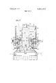
- FIG. 1 is an axial section through the machine showing the rollers in their rest position.
- FIG. 2 shows the machine illustrated in FIG. 1 with the rollers in their working position.
- FIG. 3 is a diagrammatic view on the line IIIIII of FIG. 2.
- FIG. 4 is a variant of FIG. 3.
- FIG. 5 is a section similar to FIG. 2 through a variant in which the teeth of the rollers extend through the extrusion slot.
- FIG. 6 is a diagrammatic axial section through an embodiment in which rotation of the toothed rollers or wheels about their own axes is positively controlled.
- FIG. 7 is a diagrammatic axial section through an embodiment similar to that shown in FIG. 5, except that in this case the tooth wheels are situated outside the extruded sleeve.
- the'machine consists essentially of an extrusion head generally denoted by the reference 1.
- This extrusion head is formed by a cylindrical block 2 provided with a lateral bore 3 adapted to be connected to a source of plastics material under pressure (not shown), such as an extruder.
- the cylindrical block 2 is provided with an axial bore 4 which widens conically downwards at 5 to terminate in a cylindrical bore whose wall is denoted by the reference 6.
- a central core 7 which is held in place by means of a nut 8 and whose central part 9 widens downwards into a shoulder 10 whose upper face 11 is located at a predetermined distance from the face 5 of the block 2 and whose cylindrical wall 12 forms, together with the wall 6 of the block 2, an annular extrusion slot which is denoted by the reference 13 and which opens through a ring 14 positioned at a recessed level on the front face 15 of the block 2, in order to leave a cylindrical face 15 at the bottom of the block 2 to guide the sleeve issuing from the slot 14.
- the zone through which the plastics material flows from the pipe 3 to the annular slot 14 is denoted by the generalreference l6.
- Rotatable perforating means includes elements 17-36.
- a hollow shaft 19 extending beyond the extrusion head both at its upper end and at its lower end is journalled in the axis of the central core 7 by means of ball bearings 17 and 18.
- a plate 20 carrying a certain number of rollers uniformly distributed around its periphery is fixed to the lower end of the hollow shaft 19.
- Each of the rollers such as those denoted by the references 21 and 22 is freely mounted by means of ball bearings 23, 24 on axles 25, 26 held in place by nuts 27, 28.
- Each of the rollers is in the form of a frustum whose major base 29, 30 is parallel to the front face of the cylindrical block 2.
- Each roller such as those denoted by the references 21 and 22, is provided around its periphery with teeth 31, 32 pointed or rectangular in shape, as shown by the teeth 33 and 34 in FIG. 3, which shows a plate comprising, in addition to the rollers 21 and 22, two rollers 35 and 36.
- a drive means in the form of a pulley 37 cooperating with a belt 38 is keyed to the hollow shaft 19, whilst a rod 39 extends through the hollow shaft 19, carrying a template 41 at its lower end 40, which extends beyond the hollow shaft 19.
- the rod 39 is permanently fixed at its upper end to a bracket 42 integral with a fixed part of the machine.
- the hollow shaft 19 is rotated at high speed, taking with it the plate 20 and the various rollers 21, 22 and 35, 36 for example in the direction of arrow 43', the hollow shaft 19 being lifted upwards by means (not shown).
- rollers When the aforementioned rollers reach a level at which their teeth begin to come into contact with the tubular wall 43, they begin by decelerating and then rotate in the opposite direction to the arrow 43', Le. clockwise in FIG. 3, as indicated by the various arrows alongside-the various rollers. If the hollow shaft 19 continues to be lifted, the various teeth 31 to 34 penetrate through the tubular wall 43 and the machine then reaches its working position, as shown in FIG. 2, although the faces 19 and 20 of the rollers must clearly not be in contact with the front face 15 of the block 2, to ensure that they are not slowed down by friction.
- each roller forms in the wall 43 perforations or openings aligned along a helical path, these openings subsequently being enlarged by the passage of the wall 43, perforated beforehand, over the template 41.
- FIG. 3 shows rollers with rectangular teeth 35 and 36 alternating with rollers with pointed teeth 21 and 22.
- rollers with rectangular teeth on the plate 20, in which case the wall 43 is only perforated by rectangular openings which can be aligned along generatrices or staggered from one line to the other.
- FIG. 2 Various possible configurations (A. B, C, D) are shown by way of example in FIG. 2.
- intervals between the holes are variable on the one hand in dependence upon the velocity of the longitudinal traction applied to the wall 43 extruded through the slot 14, and on the other hand in dependence upon the rotational speed of the hollow shaft 19 and, hence, in dependence upon the rotational speed of the rollers.
- rollers such as 21, 22 and 35, 36 are not positively driven.
- a pinion transmission is provided to enable these rollers to be driven positively from the rotation of the shaft 19 without having to modify the function of the machine in any way for this purpose, in addition to which one or other of the rollers, for example the roller 35 (FIG. 4), can be provided with a non-toothed zone 35' to leave an intact axial zone in the perforated sleeve.
- the particular advantage of the machine according to the invention is embodied in the extremely high production rate which is made possible by virtue of the fact that the elements used to form the openings in the extruded sleeve 43 are rotating elements which are not subjected to any alternating or flapping movement.
- FIG. 5 corresponds substantially to the machine shown in FIG. 2 and, in these two figures, the same components are denoted by the same references.
- the front face 15 of the cylindrical block 2 is situated at the same level as the front face 10 of the shoulder l0, and that the toothed wheels 21 and 22 are mounted on the plate 20 in such a way that the teeth 14 of the wheels, such as the wheel denoted by the reference 21, penetrate through the extruded sheet by only a few tenths of a millimetre so that they just perforate this sheet, which is obtained by extrusion through the annular slot defined by the two coaxial cylindrical faces 12 and 13 of the shoulder 10 and of the block 2, respectively.
- the perforations are made just as the tubular sleeve issues from the extrusion slot, and they are well-defined by virtue of the particular arrangement of the toothed wheels on the plate
- the extrusion head 1 of theembodiment shown in FIG. 6 is substantially identical with that shown in FIG. 1 and the same references have been used to denote the same components, although it should be noted that the front face 15 of the cylindrical block 2 is situated at the same level as the front face 10' of the shoulder 10, as described above with reference to FIG. 5, and that the toothed rollers 21 and 22 are shown in the working positions.
- the rotatable perforating means also includes elements 46-50 and 46' t0 48'.
- each of the wheels 21 and 22, which are mounted for rotation on the plate 20 is carried by an axle 46, 46' whose stub 47, 47 extends through the plate 20 and carries a toothed pinion 48, 48' fixed to the axle by means of a pin 49.
- Each of these pinions such as 48, 48' meshes with a fixed toothed ring 50 shown in the drawing as being integral with the template 41, which is itself fixed to the bracket 42 of the machine frame through the rod 39.
- the toothed wheels rotate about the axis 19 of the die, each rotating about its own axis with extreme precision by virtue of the fact that its toothed pinion meshes with the toothed ring which ensures that one and the same tooth of a wheel will always perforate the extruded sleeve in the same angular position. It is possible in this way to obtain extremely good vertical alignment of the openings formed in the tubular wall.
- the machine shown in FIG. 7 corresponds in principle to the machines described above, the only difference being that, in this case, the toothed wheels or rollers are situated outside the extruded sleeve.
- the rotatable perforating means includes elements 68-78, 7477 and 74".
- a shaft 53 is mounted in a cylindrical block 51 equipped with heating means 52, being kept in position by a nut 54. This shaft 53 extends through a chamber 56 communicating with a radial bore 57 connected to an extruder (not shown) for delivery of the plastics material.
- the cylindrical'block 51 has a bore 58 with a larger diameter than the shaft 53, and into the bottom 59 of this block is screwed a nut 60 formed with a hole 61 equal in diameter to the bore 58.
- the bore 61 extends downwards through a widened section 62, terminating in a cylindrical section situated opposite and at a slight distance from a widened wall 64 and a collar 65 on the lower end of the shaft 53.
- the pasty plastics material coming from the extruder enters the extrusion head 1 through the radial bore 57 and, after passing through the chambers 56, 66, 67, it leaves the extrusion head through the annular-slot 68
- a pulley wheel 71 is mounted on a cylindrical bearing surface 69 of the nut 60 by means of a ball bearing 70.
- a trapezoidal belt 72 travels around this pulley 71, rotating it about the shaft 53 by suitable means (not shown).
- Bores 73, 73 are formed in the pulley 71 parallel to the shaft 53, axles 74, 74, kept in place by the nuts 75, 75', being freely mounted in these bores.
- axles 74, 74 carry pinions 76, 76" which rotate with them by means of keys of which only the key 76' is shown. Toothed wheels or rollers 77, 77 whose teeth penetrate the sheets of plastics material issuing through the extrusion slot or die 68, are fixed by suitable means (not shown) to that end of the axles 74, 74 opposite to the end carrying the nuts 75, 75 or are integral with the axles 74, 74'.
- the pitch circle of the pinions 76, 76 forms a tangent to the extension of the outer wall or inner wall of the sleeve extruded through the annular extrusion slot 68, or to the extension of the central cylindrical surface of theaforementioned sleeve.
- the nut 60 is provided at the level of the pinions 76, 76" with a toothed ring 78 with which these pinions mesh.
- the mesh pattern can also be modified by changing the speed of rotation of the wheels 77, 77 about their own axes,,for example by using pinions 76, 76" with a greater or lesser diameter.
- the pulley 71 comprises more than two wheel assemblies 77, 77', although the others have not been shown in the interests of clarity.
- the tubular network described above is made from a plastics material, preferably from a thermoplastic material, in particular PVC, polyethylene or polypropylene for example, although this list is by no means complete.
- a plastics material preferably from a thermoplastic material, in particular PVC, polyethylene or polypropylene for example, although this list is by no means complete.
- any plastics material which can be converted into a paste in the extruder and which allows the tubular perforated network obtained to harden by passage through a bath of cooling water following the extrusion head in conventional manner.
- a machine for producing a tubular perforated sleeve by extrusion of plastic material of the type having a cylindrical extrusion head having an annular slot for forming a solid-walled tubular sleeve during use, and means for enlarging perforations by at least one of transverse or longitudinal drawing of the sleeve wherein the improvement comprises means for perforating the sleeve comprising at least one toothed roller mounted for rotation about an axis parallel to and spaced from the longitudinal axis of the cylindrical extrusion head in that the roller teeth penetrate through the tubular sleeve after the sleeve has issued from the extrusion head, means mounting said roller for rotation about the longitudinal axis of the extrusion head and means for effecting rotation of said roller about both the longitudinal axis of the extrusion head and its axis of rotation to perforate the sleeve with the rotating teeth.
- said means mounting said roller comprises a shaft journalled on the axis of the extrusion head and a support member integral with the shaft on which said roller is rotationally mounted.
- said means for effecting rotation comprises pinion means for positively rotating the roller about its axis.
- a machine as claimed in claim 1 including a plurality of rollers, at least one having rectangular teeth and at least one having pointed teeth with a rectangular toothed roller alternating with a pointed toothed roller.
- roller is disposed at the level of the opening of the extrusion slot
- means for effecting rotation comprises a pinion having a pitch circle which is tangential to the extension of the outer and inner face of the extrusion slot and to the extension of the central cylindrical surface passing through the extrusion slot.
- roller and pinion, together with the toothed ring are situated inside the tubular sleeve.
- roller and pinion, together with the toothed ring are situated outside the tubular sleeve.
- roller has one circumferential section with no teeth.
- a machine for perforating an extruded tubular workpiece of the type having an extrusion head having an annular extruding slot for extruding a solid walled tubular workpiece during use wherein the improvement comprises rotatable perforating means mounted adjacent said extrusion head for rotation around the circumference of the extruded workpiece for perforating said tube in response to the rotational movement of the rotatable perforating means.
- said rotatable perforating means comprises at least one rotatably mounted toothed roller rotatable about an axis different from the longitudinal axis of the extruding slot and means mounting said roller in a perforating position wherein the teeth thereof penetrate the extruded workpiece during the rotation of the rotatable perforating means around the circumference of the extruded workpiece thereby effecting rotation of said roller about its axis of rotation.
- said rotatable perforating means further comprises means for positively driving said roller about its axis of rotation in response to the rotation thereof around the circumference of the extruded workpiece.
- said means for positively driving said roller comprises a shaft integrally connected to the axis of said roller, and a toother gear fixedly connected to said roller and rotatable therewith about axis of rotation and a pinion gear fixedly connected to the extrusion head and meshing with said toothed gear.
- a machine according to claim 14 comprising a plurality of rollers wherein at least one has teeth having a rectangular configuration and at least one has teeth having a pointed configuration and wherein the two types of rollers are alternately positioned.
- said means mounting said roller in said perforating position comprises a rotatably driven shaft having its longitudinal axis colinear with the longitudinal axis of the extrusion slot, a discal member coaxially mounted around said shaft and rotatable therewith and on which said roller is rotatably mounted and wherein the axis thereof is parallel to and spaced from the longitudinal axis of the extruding slot.
Landscapes
- Engineering & Computer Science (AREA)
- Mechanical Engineering (AREA)
- Manufacturing & Machinery (AREA)
- Life Sciences & Earth Sciences (AREA)
- Forests & Forestry (AREA)
- Extrusion Moulding Of Plastics Or The Like (AREA)
Applications Claiming Priority (2)
| Application Number | Priority Date | Filing Date | Title |
|---|---|---|---|
| FR7143207A FR2161820A1 (en) | 1971-12-02 | 1971-12-02 | Perforated plastic jacket prodn - using appts with extrusion head and perforating cogwheels |
| FR7240691A FR2206175A2 (en) | 1972-11-16 | 1972-11-16 | Perforated plastic jacket prodn - using appts with extrusion head and perforating cogwheels |
Publications (1)
| Publication Number | Publication Date |
|---|---|
| US3841815A true US3841815A (en) | 1974-10-15 |
Family
ID=26216751
Family Applications (1)
| Application Number | Title | Priority Date | Filing Date |
|---|---|---|---|
| US00310784A Expired - Lifetime US3841815A (en) | 1971-12-02 | 1972-11-30 | Machine for producing perforated sleeves |
Country Status (9)
| Country | Link |
|---|---|
| US (1) | US3841815A (enExample) |
| BE (1) | BE792029A (enExample) |
| CA (1) | CA971715A (enExample) |
| GB (1) | GB1400084A (enExample) |
| IL (1) | IL40927A (enExample) |
| IT (1) | IT969274B (enExample) |
| LU (1) | LU66571A1 (enExample) |
| NL (1) | NL7215966A (enExample) |
| PL (1) | PL78973B1 (enExample) |
Cited By (11)
| Publication number | Priority date | Publication date | Assignee | Title |
|---|---|---|---|---|
| US3947174A (en) * | 1972-10-20 | 1976-03-30 | Hureau Jean Claude | Apparatus for reproducing perforated seamless tubular films by means of compressed air |
| US4038008A (en) * | 1974-02-11 | 1977-07-26 | Conwed Corporation | Production of net or net-like products |
| US4189292A (en) * | 1978-03-14 | 1980-02-19 | Hubert Gaillard | Extruding head for making reticulated seamless tubes |
| US4239830A (en) * | 1979-03-29 | 1980-12-16 | Harry Ball | Webbed plastic tubing |
| US4303609A (en) * | 1978-01-03 | 1981-12-01 | Jacques Hureau | Process for extruding a thermoplastic sheath in the form of a tubular film provided with perforations and device for carrying out the process |
| US4470942A (en) * | 1981-03-31 | 1984-09-11 | R.D.B. Plastotecnica S.P.A. | Process and equipment to obtain a plate provided with holes directly by extruding plastic materials |
| FR2572991A1 (fr) * | 1984-11-13 | 1986-05-16 | Nortene Sa | Gaine tubulaire en matiere plastique et dispositif pour sa realisation |
| FR2643013A1 (fr) * | 1989-02-13 | 1990-08-17 | Hureau Jacques | Dispositif pour la realisation de grillages comportant des ajourages ou evidements repartis sur leur surface |
| US20030074937A1 (en) * | 2000-04-04 | 2003-04-24 | Shafirkin David Isaakovich | Method for preventing unauthorized unlocking of a code unit of a device of a lock variety |
| US6905286B2 (en) | 2001-03-12 | 2005-06-14 | Totaku Industries, Inc. | Porous pipe and apparatus and method of producing the same |
| USD534788S1 (en) * | 2003-04-11 | 2007-01-09 | Lewmar Limited | Windlass winch capstan |
Families Citing this family (1)
| Publication number | Priority date | Publication date | Assignee | Title |
|---|---|---|---|---|
| CN109127947B (zh) * | 2018-10-15 | 2023-09-15 | 苏州红荔汽车零部件有限公司 | 汽车座椅头枕管的排齿成形模具 |
Citations (3)
| Publication number | Priority date | Publication date | Assignee | Title |
|---|---|---|---|---|
| US1369522A (en) * | 1919-05-12 | 1921-02-22 | Dochnal Frank | Manufacture of hollow tile and the like |
| US3086246A (en) * | 1961-03-03 | 1963-04-23 | Talon Inc | Method of making slide fasteners |
| US3714310A (en) * | 1970-10-30 | 1973-01-30 | Conwed Corp | Method for making reticulated tubular net |
-
1972
- 1972-11-22 GB GB5403372A patent/GB1400084A/en not_active Expired
- 1972-11-24 NL NL7215966A patent/NL7215966A/xx unknown
- 1972-11-24 CA CA157,490A patent/CA971715A/en not_active Expired
- 1972-11-27 IL IL40927A patent/IL40927A/xx unknown
- 1972-11-29 BE BE792029A patent/BE792029A/xx not_active IP Right Cessation
- 1972-11-30 LU LU66571A patent/LU66571A1/xx unknown
- 1972-11-30 US US00310784A patent/US3841815A/en not_active Expired - Lifetime
- 1972-12-01 IT IT13052/72A patent/IT969274B/it active
- 1972-12-02 PL PL1972159346A patent/PL78973B1/pl unknown
Patent Citations (3)
| Publication number | Priority date | Publication date | Assignee | Title |
|---|---|---|---|---|
| US1369522A (en) * | 1919-05-12 | 1921-02-22 | Dochnal Frank | Manufacture of hollow tile and the like |
| US3086246A (en) * | 1961-03-03 | 1963-04-23 | Talon Inc | Method of making slide fasteners |
| US3714310A (en) * | 1970-10-30 | 1973-01-30 | Conwed Corp | Method for making reticulated tubular net |
Cited By (13)
| Publication number | Priority date | Publication date | Assignee | Title |
|---|---|---|---|---|
| US3947174A (en) * | 1972-10-20 | 1976-03-30 | Hureau Jean Claude | Apparatus for reproducing perforated seamless tubular films by means of compressed air |
| US4038008A (en) * | 1974-02-11 | 1977-07-26 | Conwed Corporation | Production of net or net-like products |
| US4303609A (en) * | 1978-01-03 | 1981-12-01 | Jacques Hureau | Process for extruding a thermoplastic sheath in the form of a tubular film provided with perforations and device for carrying out the process |
| US4189292A (en) * | 1978-03-14 | 1980-02-19 | Hubert Gaillard | Extruding head for making reticulated seamless tubes |
| US4239830A (en) * | 1979-03-29 | 1980-12-16 | Harry Ball | Webbed plastic tubing |
| US4470942A (en) * | 1981-03-31 | 1984-09-11 | R.D.B. Plastotecnica S.P.A. | Process and equipment to obtain a plate provided with holes directly by extruding plastic materials |
| FR2572991A1 (fr) * | 1984-11-13 | 1986-05-16 | Nortene Sa | Gaine tubulaire en matiere plastique et dispositif pour sa realisation |
| US4636162A (en) * | 1984-11-13 | 1987-01-13 | Nortene | Apparatus for making a tubular sheath of plastic material |
| FR2643013A1 (fr) * | 1989-02-13 | 1990-08-17 | Hureau Jacques | Dispositif pour la realisation de grillages comportant des ajourages ou evidements repartis sur leur surface |
| EP0383664A1 (fr) * | 1989-02-13 | 1990-08-22 | Jacques Hureau | Dispositif pour la réalisation de grillages comportant des ajourages ou évidements répartis sur leur surface |
| US20030074937A1 (en) * | 2000-04-04 | 2003-04-24 | Shafirkin David Isaakovich | Method for preventing unauthorized unlocking of a code unit of a device of a lock variety |
| US6905286B2 (en) | 2001-03-12 | 2005-06-14 | Totaku Industries, Inc. | Porous pipe and apparatus and method of producing the same |
| USD534788S1 (en) * | 2003-04-11 | 2007-01-09 | Lewmar Limited | Windlass winch capstan |
Also Published As
| Publication number | Publication date |
|---|---|
| DE2258809A1 (de) | 1973-06-14 |
| NL7215966A (enExample) | 1973-06-05 |
| BE792029A (fr) | 1973-05-29 |
| LU66571A1 (enExample) | 1973-02-01 |
| DE2258809B2 (de) | 1976-01-02 |
| GB1400084A (en) | 1975-07-16 |
| IL40927A0 (en) | 1973-01-30 |
| IT969274B (it) | 1974-03-30 |
| CA971715A (en) | 1975-07-29 |
| IL40927A (en) | 1975-07-28 |
| PL78973B1 (en) | 1975-06-30 |
Similar Documents
| Publication | Publication Date | Title |
|---|---|---|
| US3841815A (en) | Machine for producing perforated sleeves | |
| US3193604A (en) | Process and apparatus for producing ribbed sheeting | |
| US2919467A (en) | Production of net-like structures | |
| US3384692A (en) | Method for producing square-mesh net structure | |
| RU2104156C1 (ru) | Способ изготовления неоднородного материала, устройство для его осуществления (варианты) и неоднородный материал | |
| US3394431A (en) | Apparatus for extruding plastic mesh, lace or net fabrics | |
| US4806303A (en) | Method and apparatus for the production of perforated films, particularly perforated films of plastics material for sanitary articles | |
| EP0166245A2 (de) | Verfahren und Vorrichtung zum kontinuierlichen Herstellen von länglichen Hohlkörpern, insbesondere von Schläuchen, Rohren oder Innenlinern für solche, aus einem flüssigen Material, wie Reaktionsgemisch oder Schmelze | |
| US3308220A (en) | Plastic mesh producing machine | |
| US3270370A (en) | Extruded plastic net | |
| US3589958A (en) | Method for the preparation of filament reinforced sheet | |
| US4636162A (en) | Apparatus for making a tubular sheath of plastic material | |
| US3118180A (en) | Method and apparatus for extruding two color mesh fabrics | |
| WO1991004141A1 (de) | Verfahren zum herstellen eines körpers aus extrudierbarer masse, vorrichtung zum durchführen des verfahrens, extrusionsmundstück für eine derartige vorrichtung und nach dem verfahren hergestellter körper | |
| US3291879A (en) | Method and apparatus for fabricating plastic web | |
| US3358329A (en) | Extrusion apparatus and products therefrom | |
| US3616080A (en) | Apparatus for extrusion of strengthened plastic netting | |
| US3895992A (en) | Apparatus for manufacturing foamed plastic | |
| US3478139A (en) | Method of extruding tubular webbing and cross-ribbed tubular film | |
| US3418687A (en) | Extruding apparatus | |
| GB1173130A (en) | Apparatus for Continuously Manufacturing Synthetic Resin Pipe | |
| US3179974A (en) | Stretching frame | |
| DE2227858A1 (de) | Falschzwirnkraeuselmaschine | |
| US3682749A (en) | Apparatus for the preparation of filament reinforced sheet | |
| AT224898B (de) | Vorrichtung zum Strangpressen von schlauchförmigen, plattenförmigen oder folienartigen Gebilden aus Kunststoff |
Legal Events
| Date | Code | Title | Description |
|---|---|---|---|
| AS | Assignment |
Owner name: IWB WIRTSCHAFTSBERATUNGS-ANSTALT, AEULSTRASSE 38, Free format text: ASSIGNMENT OF ASSIGNORS INTEREST.;ASSIGNOR:LABARRE, MAURICE;REEL/FRAME:004029/0470 Effective date: 19820314 |
|
| STCF | Information on status: patent grant |
Free format text: PATENTED FILE - (OLD CASE ADDED FOR FILE TRACKING PURPOSES) |