US3830706A - Heat and mass transfer between two liquids of different vapor pressure via a common vaporous component - Google Patents
Heat and mass transfer between two liquids of different vapor pressure via a common vaporous component Download PDFInfo
- Publication number
- US3830706A US3830706A US00188457A US18845771A US3830706A US 3830706 A US3830706 A US 3830706A US 00188457 A US00188457 A US 00188457A US 18845771 A US18845771 A US 18845771A US 3830706 A US3830706 A US 3830706A
- Authority
- US
- United States
- Prior art keywords
- liquid
- stream
- vapor
- vapor pressure
- heat
- Prior art date
- Legal status (The legal status is an assumption and is not a legal conclusion. Google has not performed a legal analysis and makes no representation as to the accuracy of the status listed.)
- Expired - Lifetime
Links
Images


Classifications
-
- B—PERFORMING OPERATIONS; TRANSPORTING
- B01—PHYSICAL OR CHEMICAL PROCESSES OR APPARATUS IN GENERAL
- B01D—SEPARATION
- B01D1/00—Evaporating
- B01D1/14—Evaporating with heated gases or vapours or liquids in contact with the liquid
-
- Y—GENERAL TAGGING OF NEW TECHNOLOGICAL DEVELOPMENTS; GENERAL TAGGING OF CROSS-SECTIONAL TECHNOLOGIES SPANNING OVER SEVERAL SECTIONS OF THE IPC; TECHNICAL SUBJECTS COVERED BY FORMER USPC CROSS-REFERENCE ART COLLECTIONS [XRACs] AND DIGESTS
- Y02—TECHNOLOGIES OR APPLICATIONS FOR MITIGATION OR ADAPTATION AGAINST CLIMATE CHANGE
- Y02A—TECHNOLOGIES FOR ADAPTATION TO CLIMATE CHANGE
- Y02A20/00—Water conservation; Efficient water supply; Efficient water use
- Y02A20/124—Water desalination
-
- Y—GENERAL TAGGING OF NEW TECHNOLOGICAL DEVELOPMENTS; GENERAL TAGGING OF CROSS-SECTIONAL TECHNOLOGIES SPANNING OVER SEVERAL SECTIONS OF THE IPC; TECHNICAL SUBJECTS COVERED BY FORMER USPC CROSS-REFERENCE ART COLLECTIONS [XRACs] AND DIGESTS
- Y10—TECHNICAL SUBJECTS COVERED BY FORMER USPC
- Y10S—TECHNICAL SUBJECTS COVERED BY FORMER USPC CROSS-REFERENCE ART COLLECTIONS [XRACs] AND DIGESTS
- Y10S159/00—Concentrating evaporators
- Y10S159/17—Two liquids
Definitions
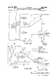
- ABRAHAM KOGAN his ATTORNEYS A. KOGAN Aug. 20, 1974 HEAT AND MASS TRANSFER BETWEEN TWO LIQUIDS 0F DIFFEREflT VAPOR PRESSURE VIA A COMMON VAPOUR COMPONENT Filed Oct. 12. 1971 6 Sheets-Sheet a INVENTOR.
- the process comprises the steps of flowing the liquid of lower vapor pressure along a channel which includes an apertured partition, flowing solely the homogenous liquid of higher vapor pressure along a second channel which is separated from the apertured partition by a vapor transfer region, and evolving a vapor from the liquid of lower vapor pressure.
- the vapor evolved vapor transfer region beneath the apertured partition a vapor pressure higher than the hydrostatic pressure of the liquid of lower vapor pressure.
- the vapor evolved from the liquid of higher vapor pressure is thereby introduced into the liquid of lower vapor pressure through the apertured partition while preventing the downward flow of the liquid of lower vapor pressure through the apertured partition.
- the present invention relates to improvements in the transfer of heat and/or mass from a homogeneous liquid of a higher vapor pressure to another liquid of lower vaporpressure.
- the present invention relates to the transfer of heat and/or mass between a first liquid stream, which is a solution, to a second liquid stream.
- the first liquid stream increases in concentration and decreases in temperature while imparting heat and mass to the second liquid stream.
- the system of Lewis et a1. includes an air-evaculated chamber which is separated into upper and lower regions by an apertured partition.
- a cold liquid is caused to flow through the upper region across the apertured partition and warm liquid caused to flow through the lower region beneath the apertured partition.
- the level of the stream of warm liquid is made sufiiciently low so that a vapor transfer region exists between this stream and the apertured partition.
- an inert gas is pumped into the lower region at a point beneath the level of the warm liquid so as to increase the pressure in the vapor transfer region and prevent the cold liquid from dripping downward into the lower region through the apertured partition.
- the inert gas passes upward through the apertured partition and through the cold liquid and is removed from the upper region, together with any noncondensable gases which may have accumulated there, by a vacuum pump.
- the Bauer system is similar to the system of Lewis et a1. except that an inert gas is not used to prevent the cold liquid from dripping downward through the apertured partition.
- the Warm liquid is mixed with a heated immiscible heat transfer liquid to increase its temperature and cause it to flash. The flashing process enables the warm liquid to yield sufiicient vapor to maintain the cold liquid above the apertured partition.
- the noncondensable gases can no longer accumulate in steadily increasing concentrations to form a barrier to the heat and/or mass transfer. Instead, the noncondensable gases move under their own buoyancy to the surface of the cold liquid where they can be removed without interference with the transfer and without removal of an appreciable amount of condensable gases therewith.
- the Bauer system requires the introduction of an immiscible heat transfer liquid together with the warm liquid to be distilled into the lower region beneath the apertured partition.
- immiscible heat transfer liquid together with the warm liquid to be distilled into the lower region beneath the apertured partition.
- some of the immiscible liquid is broken up into minute droplets. These droplets are entrained with the vapor produced by the warm liquid and are carried upward through the apertures into the upper stream of cold liquid or condensate.
- the homogeneous liquid of higher vapor pressure will evolve a vapor that builds up inthe vapor trans fer region beneath the apertured partition.
- the difference in vapor pressures between the liquid of higher vapor pressure and the liquid of lower vapor pressure is chosen (e.g., by controlling the temperatures of the two liquids) so that the vapor pressure in the vapor transfer region will be higher than the pressure above the liquid-of lower vapor pressure plus the hydro-static pressureof the liquid of lower vapor pressure.
- homogeneous liquid of higher vapor pressure is introducedinto the channel or region beneath the apertured partition.
- the system according to the present invention is thus distinguishable from the systems of Lewis et a1. and Bauer which introduce, respectively, an inert gas and an immiscible liquid phase into this region.
- homogeneous liqui as used herein is intended to define a liquid containing but a single miscible liquid phase; e.g., a true solution as contrasted with an emulsion or a dispersion.
- the liquid of lower vapor pressure is an overhead stream and the liquid of higher vapor pressure is an underneath stream.
- a plurality of heat and/or mass transfer stages are accommodate within a single apparatus housing bysubdividing the housing into a plurality of chambers. Also, successive housings are connected one with another so that the two liquid streams flow from stage to stage and from housing to housing with the cooler overhead stream flowing through successive stages or chambers within each housing by gravity and the warmer lower stream flowing through successive stages or chambers within each housing at least partially against gravity under a driving force which results from the temperature and pressure. differentials between successive chambers or stages. I
- the apertured partition To obtain maximumefficiencyflow of the vapor from the underneath to the overhead stream through the apertured partition, it is desirable to reduce as much as possible 'pres'sure losses encountered by the vapor stream flowing "through the apertures. According to the present-invention"such pressure losses can be reduced by the-shape of the apertures. Any solid protuberances on the uppersurfaceof the aperturedvplate, such as risers or slotted caps, are avoided-In preferred embodiments of thepre'sent invention the apertures have a tapering, conical or bell-" shape, with larger'area'inlets and smaller area outlets. Also, the 'axes of'the apertures are directed at an acute angle to the plate of the partition in a direction downstrearn'of the flow-of the overhead stream.
- the vapor passingfthroug-h' each" aperture is thus directed with the gerieral flow'direction-of'the overhead stream, and the disturbance. to "the flow is minimized. Moreover, the momentum' of-t-he vapor stream is not lost completely, so; that itis transferred to a large extent to the overhead liquid stream.
- The-"smaller.thedrop in vapor temperature in passing from one liquidrstre'am to the other the more complete will-bethe' heatgrecovery of the system of the present inventio'nx 'l he smaller-the differencein temperature between the two liquidstreams',- the less will be the heat per un'it-mass of' product rejected .to the outside at the low" temperature end I of. the. .system and,- consequently, the-lessadditionalheatwillbezlrequired from an external source at the high temperatureeend of the system.
- the efliciency'ofthesystemofthe present invention is therefore" 1 dependent .;upon ,ithe rate of vapor condensation which may be maintained with a given temperature dilference between-the twoliquid streams. Due to the absencezrof an inert gas Oran-immiscible liquid in the region beneath the-*apertured partition, the transfer of vapor. between the 'liquidzof.
- Anothe'r'advantage ofthe-presen't invention vis-a-vis the system .oftBa'uer is a greater purity in the condensed quires the; introductionof an immiscible heat transfer liquid together with the feed solution into the channel region beneath the apertured partition. Due to the chaotic process of flash evaporation, the immiscible liquid is partially broken up into minute droplets, some of which pass upward through the apertures into the upper liquid stream; contaminating the condensate. Because only a homogeneous liquid is used as the liquid of higher vapor pressure in the system of the present invention, the condensate will be so pure as to require no filtration or other subsequent processing prior to use.
- Still another advantage of the present invention vis-avis the system of Bauer is that, due to the absence of an immiscible liquid, the liquid of higher vapor pressure is allowed to flash evenly and continuously as it passes from stage to stage.
- the liquid of higher vapor pressure will tend' to separate out from the immiscible liquid along the tortuous path through the multi-stage housing due to buoyancy and due to the centrifugal force at the turns.
- large droplets of the liquid of higher vapor pressure will tend to coalesce in the upward flowing stream and the supply of heat from the immiscible liquid to the drops of the liquid of higher vapor pressure will be hindered.
- the immiscible liquid is not itself capable of flashing, if a substantial amount of the liquid of higher vapor pressure is allowed to separate from the immiscible liquid, it will be diflicult to maintain the flow of immiscible liquid through the flashing risers and, eventually, as the immiscible liquid is collected in the intermediate stages of the apparatus, the upward flow of all liquid Will be halted entirely.
- FIG. 1 is a schematic side elevation of the heat and/or mass transfer apparatus of the present invention
- FIG. 2 is a schematic side elevation in cross-section ihfwing one of the multiple stage housings illustrated in FIGS. 3, 4 and 5 are longitudinal cross-sectional views of different forms of gas transfer apertures for use in the apparatus shown in FIGS. 1 and 2;
- FIG. 6 is a schematic perspective view of still another form of gas transfer aperture
- FIG. 6A is a cross-sectional view taken along the line 6A6A of FIG. 6;
- FIG. 7 is a fragmentary side elevation in cross-section showing an alternative embodiment of multiple stage housing;
- FIG. 8 is a schematic drawing illustrating another form of multiple stage housing
- FIGS. 9A and 9B are schematic drawings'illustrating an alternative system embodying the present invention.
- FIG. 10 is a schematic drawing illustrating a further form of multiple stage housing
- a FIGLll is a fragmentary schematic drawing illustrating a still further form of multiple stage housing DESCRIPTION OF THE PREFERRED EMBODIMENTS
- the present invention is applicable" generally to systems in which a gas can be-evolved from one underneath liquid stream and transferred to'another overhead liquid stream to transfer heat and/or'ma'ss thereto or react therewith, it is described herein'intheform ofa distillation system in which water vapor is" evolved'from a salt water-stream and condensed ina fresh water stream to transfer both heat and mass to the fresh water stream.
- saline water to be distilled is introduced-into the 'dis'tillation system through an intake'.10,-'lieated' in"a*heat iexchanger -11 and in a heater 12, 'fedseriatim throug'h a plurality of housings or enclosures 13,14, 15,16, 17 and 18 wherein water vapor-is evolved therefrom and converted into fresh water before the more concentrated saline water is discharged through a conduit 20 by a pump 21.
- the fresh water condensed from the vapor evolved from the saline water flows through these housings seriatz'm but in a countercurrent direction to the flow of the saline water.
- the converted fresh water Upon discharge from the housing 13, the converted fresh water is carried through a conduit 22 by a pump 23 to heat exchanger 11 in which it is brought into heat exchange relationship with saline water intake to heat the latter.
- the converted fresh water is then, in part, carried to storage by a conduit 24 and, in part, returned to the housing 18 by a conduit 25 to repeat the cycle.
- the pumps 26 assist in carrying the fresh water from the lower level discharge of one housing to the higher level inlet of the succeeding housing.
- the housings 13 through 18 are of generally trapezoidal shape and are oriented at appropriate angles for reasons which will be explained below.
- the interiors of these housings are of similar construction.
- a typical housing for example the housing 16 illustrated in FIG. 2, is subdivided into a plurality of stages 16a, 16b, 16c and 16d by vertical partitions 27. Each stage, in turn, is subdivided into upper and lower sections a and b, respectively, by means of an apertured partition 28.
- the partitions 28 cooperate with the side walls of the housings to form a series of flow channels for the fresh water.
- the warmer salt water or brine enters the housing 16 at the left through a conduit 29, passing into the lower section b of the stage 16a.
- the brine continues to flow through the stages 16a, 16b, 16c and 16d in sequence, passing. from stage to stage through a restricted passage 30 in the lower end of each of the vertical partitions 27.
- the brine ultimately is discharged from the last stage 16d through a conduit 31 which carries the brine to the next housing 17.
- the cooler overhead stream of fresh water enters the housing at the right through a conduit 32 and flows by gravity through the stages 16d, 16c, 16b and 16a in sequence, passing from stage to stage through a restricted passage 33 defined between the upper end of the vertical partition 27 and a baffle 34 depending from the top of the housing and spaced apart from the top of the partition 27 in a downstream direction.
- the downstream declination of the flow channels through each of the successive stages maintains a shallow stream flow at a supercritical rate of flow.
- the fresh water ultimately is discharged from the last stage 16a through a conduit 35 which carries it to the next housing 15.
- air and noncondensable gases are evacuated from the upper regions of each of the stages within the housing 16, maintaining very low pressure in the interiors thereof
- the stages are sealed 013? from each other by the passage of the liquid streams through the restricted passages 30 and 33.
- the heated salinewater flows from stage to stage within the housing against gravity.
- a plate 36 downwardly inclined in a downstream direction is accommodated within each of the stages of the housing and cooperates with the side walls of the housing to form a flow channel for the saline water.
- the saline water enters the lower section b of the stage 16a beneath the left end of the plate 36.
- the plate 36 is perforated, at least at the left end thereof, and because of the low pressure in the section b, the saline water penetrates in a fountain-like manner through the apertures in the plate 36, flashing into vapor and carrying the saline stream across the upper surface of the plate while vapor is evolved from the saline stream.
- the saline stream passes from stage to stage through the apertures 30 and against the influence of gravity, as described in the above-mentioned patent. Since there is a saturated vapor pressure ineach stage, when the saline water flows into the next stage at lower pressure the consequent cooling of-the saline water evolves vapor, so that in each stage both heat and mass. are transferred from the lower warmer stream to the upper cooler stream. a
- the overhead and underneath streams will diverge in the downstream directions of the saline stream and hence the housings 13 through 18 are preferably of trapezoidal shape.
- the distillation of the saline water is carried on in a succession of different housings, as described above. The declination of the flow channels in each of the stages makes it possible to maintain both streams at equal rates of flow and at shallow depths. This in turn dictates the angle of orientation of the housing.
- the vapor pressure established in the vapor transfer region of each stage is sufficiently high to overcome the hydrostatic head of pressure presented by the overhead shallow stream of converted water, and in consequence the overhead stream continues to flow across the apertured flow channel under the influence of gravity instead of percolating downwards into the lower section b.
- apertures inthe transverse partitions 28 between the upper and lower sections of each distillation stage Various considerations govern the choice of the size, the shape and the distribution of the apertures inthe transverse partitions 28 between the upper and lower sections of each distillation stage.
- these apertures must have a large enough overall area to allow for the effective penetrations of the vapor into the body of the converted water stream flowing on the apertured partition.
- the diameter of each aperture must be limited so as'to avoid downflow of the converted water stream through the apertures.
- the overall area of the apertures depends both on the number of apertures per given area and on the size of each aperture. While theoretically it would be desirable to dis tribute the apertures as closely together as possible, a limiting factor is that when the apertures are too close together it is found that the bubbles of vapor which pass through these closely spaced apertures into the converted water stream tend to coalescence into a single large bubble which often passes straight through the converted water stream without condensing.
- FIG.3 shows the apertures 28a intapering; conical form
- FIG. 4 shows the apertures 28b in bell shaped form.
- the aices ofthe-apertures"28c are directed at an angle to the plane' of the partition and in the same general ydirectio'n as the direction of" flow of the converted water stream-thereon.
- the vapors thus flow into the liquid in -th-e direction of fiow'thereo'f so that the momentum of vapor flow is not completely lost and is partially transmitted to the 'converted'water stream?
- the vapor bubblesfemerging from such inclined apertures tend to be elongated and inclined to the horizontal and thereby present an extended contact surface to the converted water stream so as to facilitate condensation.
- The"partitidns shouldpreferably be insulated or made fr'orri'in'sulati'n'g material to prevent the vapor from condensing-on the underside's thereof.
- the converted water stream was introduced into the housing in the last stage aha-temperature of 38.8 C. whilethe heated saline water stream was" introduced-into the system in the first stage at atemperature of 44.7 C., the rate of flow of each of the "streamsbeing 15 liters per minute. It was found that the converted water stream'was'discharged from the housing at the-first 'stage at a t'empera'ture"of4l.2 C., i.e., it had undergone an increase in temperature of 2.4 C. while the heated salinewater stream didndergone a decrease in temperature of similar'magnitude'.
- the presentsystem lends itself to a continuous drainolf of no ricondensable gases; from above the overhead Since-thefbubbles of these noncondensable gases fo" 1at"the'top o'f'e'ach vapor bubble, thebubblesof' no ncoifdensable j'gas ultimately 'detach themselves from the coridens' bubblesafi' "carried by'buoyan cy' towards i frfaceofthe' (inverted vvater stream. Thisis infcontr t to a system o'f 'the' type described in the-pre- 'viously ention'e'd UJS.
- the system of the present invention produces ,a condensate of the highest purity.
- minute droplets of the immiscible liquid find their way into the condensate from the region beneath the apertures producing a cloudy emulsion which is unacceptably impure for certain purposes.
- the traces of immiscible liquid must be separated from the condensate by special emulsion-separating tech niques.
- the condensate can be used directly as drinking water without intermediate purification.
- the system of the present invention is adaptable to the system described in the above-identified patent to Kogan wherein the heated saline water stream is raised from stage to stage by the driving force which arises out of the difference in vapor pressure between the stages.
- the vapor pressure is used both to overcome the hydrostatic head of the cool liquid stream and to propel the saline water stream from stage to stage against the influence of gravity.
- the housings or enclosures were of trapezoidal shape to insure that the overall direction of gravity fiow of the converted water has a steeper inclination as compared with the overall direction of flow of the saline water which is partially against gravity under the driving force exerted by the vapor pressure. This divergence between theoverall directions of flow of the two streams is provided for in order to take care of frictional losses of the streams.
- the trapezoidal shape of the enclosure limits the number of stages in each enclosure and requires pumps to be pro.- vided between enclosures to lift theconverted water stream from theadischarge of one enclosure to the intake ofathe next.
- the housing structure shown in FIG. 7 of the drawings can be adopted to avoid or reduce the overall divergence ofthe two streams. This isiachieved by the design of the housing to recover part of the. momentum imparted by; the vapor flow to the converted waterstream while insuring equal rates of flow of the'two-stre'amer F
- The-housing 41 showninvFIG; 7 has parallel upper and lower walls and is divided by-a-zpa'rtition 42into' a lower.- evaporation section'43 and an upper condensation .section 4.4.
- the condensation section-44 is divided by means of vertical partitions245 int'o successive condensation stagest'
- theevaporation' 'section 43 is divided by vertical partitions 46 ,in'to successive evaporation stages.
- Each vertical partition 46 is formed integrally with a perforated longitudinally extending plate 47 which slopes downwardly in a downstream direction. Also, the lower end of each vertical partition 45 terminates in a curved lip or flange 48 which extends in a downstream direction. The lower curved surface is spaced from the upper surface of the partition 42 to form a flow passage from one section to the next.
- the longitudinally extending partition includes a substantially horizontal apertured portion 42a, a short rising upper surface 42b downstream of the portion 42a, and a longer descending upper surface 420 downstream of the portion 42b.
- the saline water stream 49 flows through the evaporator stages in a manner similar to the flow of the saline water in the embodiment described above in connection with FIG. 2, and at the same time the converted water stream 50 flows in a countercurrent direction through the condenser stages.
- the vapor which passes from an evaporator to a condenser stage through the apertured portion 42a transfers sufficient momentum to the converted water stream so as to cause it to climb the rising surface 42b.
- the perforated portion 42a is shown as horizontally disposed, but it can be given a slight upward slope.
- the upper surface 42a can also be curved in concave fashion so as to achieve an even flow of vapor through the apertures, thereby insuring an effective control on the thickness of the liquid layer on this portion 42a.
- This modification reduces or eliminates the divergence between the overhead and underneath streams and eliminates the necessity to provide for pumping between stages or groups of stages.
- FIG. 8 of the drawings A form of diagonally extending housing or enclosure 70 for the upper and lower streams is shown in FIG. 8 of the drawings.
- the saline water or liquid from which a gas is to be evolved enters a lower region 71 of the housing through an inlet passage 72, flows upwardly through a diverging riser 73 of diverging cross-sectional area to a first stage chamber 74, through a diverging riser 75 to a second stage chamber 76, then through a diverging riser 77 to a third stage chamber 78, then out a discharge passage 79 in the lower region of the chamber 78.
- the fresh water or liquid to which the mass and/or heat is to be transferred flows in countercurrent direction into an upper region 80 of the housing through an inlet passage 81, and then through a U-shaped passage 82 to a flow passage 83 which is in communication with the chamber 78 through perforations 84.
- the fresh water then continues its flow downwardly through a U-shaped neck 85 to a flow chamber 86 which is in communication with the chamber 76 through perforations 87, through a U-shaped passage 88 to a flow passage 89 which is in communication with the chamber 74 through perforations 90 before it is discharged from the housing through the outlet passage 91.
- the upper regions of the flow channels 83, 86 and 89 are maintained at lower pressures than the vapor pressures in the regions 78, 76 and 74, respectively.
- the vapor evolved in each of the stages 74, 76 and 78 rises, passes through the apertured flow channel for the upper stream, condensing therein to become part of the upper stream.
- obstructing fins 92 are placed in the lower ends of each riser. Also, bafiles 93 are provided in each chamber between the dischargeof the riser and the apertured channel across which the fresh water stream flows to prevent the saline water from being carried upwardly with the vapor'into the fresh water stream.
- the U-shaped passages 82, 85 and 88 isolate the pressures within the various stages and are useful in starting up the operation when the fresh water is first introduced into the upper region of the housing-
- the vaporpressure within the upper regions'83, 86 and 89- of each of the stages offers resistance to the flow of fresh water when initially starting up the system, but the build-up in the level of the upstream fresh water above each of the U-shaped passages 82, and 88 forces the flow-o condensates from stage to stage. 1
- FIGS. 9A and 9B illustrate an alternative system, embodying the present invention, for transferring heat and mass from one moving stream to another.
- lower cost and increased effieciency are achieved by transferring heat from the condensate to the saline water by means of a solid heat transfer medium.
- the saline water or liquid from which the vapor is to be evolved is heated in a heat exchanger 11 in outof-contact heat exchange relation with the condensate.
- the out-of-contact heat exchange relationship between the two liquids is less eflicient than a direct heat exchange relation between two bodies and requires the provision of a relatively costly heat exchanger in which there is a tendency for scale to form on at least the surfaces exposed to the saline water.
- FIGS. 9A and 9B show, respectively -a system and the heat cycles of the saline water, vthe fresh water and a solid heat exchange medium in which the heat exchanger is of the type shown and described inmy US. Pat. No. 3,242,975, issued Mar. 29, 1966, or in my. copending application Ser. No. 721,990, filed Apr. 17, 1968-, that is to say, a heat exchanger in which heat is transferred from one body of liquid to another by a plurality of pebbles which flow through the two bodies transferring heat from one to the other.
- make-up saline water is introduced by a pump 123 into a brine reservoir 124 in which it is mixed with the hot brine returning through a conduit 125 from a multiple stage enclosure 70 similar to the one described above in connection with FIG. 8.
- 'Blowdown is discharged from the brine reservoir by a pump 126.
- the brine is also fed through a conduit .127 by a pump 128 into the lower end of heat exchanger No. 1 where it is heated in direct contact with heated pebbles or other solid heat transfer rnedium beforeit is introduced into the enclosure 70.
- .In.passing as the. lower stream through the multiple stage enclosure 70 vapor is evolved and condensed in the upper stream flowing in countercurrent direction.
- the brine emerges from the en.- closure and is returned by conduit 125 to. the brine reservoir.
- the condensate emerging from the enclosure-70 is fed through a conduit 129 by'apump 130 totheheat exchanger No. 2.
- the condensate In passing through theheat exchanger No. 2 the condensate is brought into direct contact with the pebbles or other solid heat transfer medium to supply heat thereto.
- the cooler condensate iscarriedfrom the heat exchanger No. 2 by a. conduit 131 and partof it is returned to the enclosure 70 to flow therethrough as the upper stream, and part of his taken out of the system as product. r
- the pebbles or'other solid heat transfer medium flow by gravity iirst through the upper heat exchanger No.
- FIG. 9B A heat exchange cycle of the system of FIG. 9A is shown in FIG. 9B.
- the saline water is shown entering a brine reservoir 124 at the temperature 133 and being heated therein in direct contact with the brine leaving the enclosure 70' at a temperature level 134.
- the blowdown leaves the brine reservoir at a temperature level 135, and the saline water entering the system, also at temperature 135, is heated to a temperature 136 in the heat exchanger No. l in direct contact with the pebbles or other heated solid medium.
- the saline water then enters the enclosure 70 at approximately the temperature level 136 and passes from stage to stage, giving off heat to the fresh water flowing through the enclosure in countercurrent direction.
- the brine emerges from the enclosure 70 at the temperature level 134.
- the fresh water enters the enclosure 70 at a temperature level 137 and emerges therefrom at an elevated temperature 138, whereupon it is introduced into the heat exchanger No. 2 where it passes in direct contact with the pebbles or other solid heat transfer medium, emerging from the heat exchanger No. 2 at approximately the temperature level 137. Part of the fresh water is returned to the enclosure 70 and the remainder is removed from the system as product.
- the solid heat transfer medium passes from the heat exchanger No. 2 at a temperature level 139, then passes through the heater 132 which raises the temperature thereof to level 140.
- the solid heat transfer medium then passes in direct heat exchange relationship with the saline water in theheat exchanger No. 1 to preheat the latter while at the same time decreasing the temperature of the solid heat transfer medium to the level 141, at which temperature it is introduced into the heat exchanger No. 2.
- FIG. illustrates a modified form of a diagonally extending housing of the type described above in connection with FIG. 8.
- FIG. 10 shows a diagonally arranged enclosure provided with a inlet 151 and an outlet 152 for the lower stream and an inlet 153 and an outlet 154 for the upper stream.
- the liquid of the upper stream is passed from stage to stage through a flow channel 155 which is designed to maintain the flow of the liquid at a minimum velocity.
- the apparatus of FIG. 10 operates in the same manner as the multiple stage housing shown in FIG. 8.
- the saline water enters a reservoir 156 of the enclosure 150 through the inlet 151 and passes upwards through a riser 157 to the first stage 158. Thereafter, the saline solution proceeds to the subsequent stages 160 and 162 via the risers 159 and 161, respectively, and passes out of the enclosure through the outlet 152.
- the water vapors condense in the upper stream thus increasing slightly the volumetric rate of flow of the upper stream from stage to stage.
- the noncondensable gases which enter the upper stream appear in the form of minute bubbles, ranging in diameter from a few microns to a maximum of a few millimeters.
- the suflicient velocity not less than 40 centimeters per second and preferably above 70 centimeters per second
- the small bubbles of the noncondensable gases are carried with the liquid stream from stage to stage before they reachits upper surface.
- the upper stream and the bubbles are thoroughly mixed during'vapor penetration and condensation.
- the upper channel 155 By designing the upper channel 155 with a substantially constant cross-section to avoid stagnation regions in the upper stream which would permit the collection of nonconensable gases within the channel, it is therefore possible to reduce considerably the complexity of the evacuation system. Since, further, the vapor pressure which must be maintained in the upperregion of the reservoir 163 may be relatively high, the loss of condensable vapor that is evacuated together with the noncondensable gases may also be materially reduced.
- FIG. 11 illustrates a modification of the multistage housing embodiment of FIG. 10. This modification is designed to prevent the liquid of the upper stream from grilpping downward through the apertures into the stream e ow.
- One of the considerations in the design of the upper sections of a heat and/or mass transfer system according to the present invention is to provide for a steady flow of liquid along the upper surface of the apertured partition without encountering the phenomenon of weeping; that is, the penetration of part of the upper liquid through the lowing along. such an apertured, plate, the liquid of the upper stream is thereby constrained to followa curvilinear path and will thus be under the influence of an upwardly directed centrifugal force.
- This force though small,.. is suflicient to prevent the penetration of any of the upper liquid into the aperture of the partition wall.
- FIG. 11 An example of this particular modification, as applied to the embodiment of FIG. 10, is illustrated in FIG. 11.
- the apertured plate 165 is so curved at the region immediately preceding the apertures that the upper stream is initially directed upwards. Thereafter the apertured plate is curved downwards again, permitting the upper stream to flow in the horizontal direction. Since the upper stream is thus caused to change its direction immediately above the apertures, there results a centrifugal force which assists in avoiding the phenomenon of weeping.
- the present invention has been described herein as pertaining to the transfer of mass and/or heat from an underneath stream to an overhead stream.
- distil lation of saline water both mass and heat are transferred by the condensation of the vapor evolved from the lower stream in the upper stream.
- a gas evolved from the lower stream which does not condense in the upper stream there will be only a transfer of heat and not mass.
- the invention is also applicable to a process in which the two streams are chemical reactants, and the transfer of mass from the lower stream to the upper stream produces a chemical reaction. Under these circumstances the process in accordance with the invention is most effective for contacting intimately a gaseous (vapor) phase with a liquid phase.
- a process for transferring heat and mass from one stream of a homogeneous liquid of higher vapor pressure to another stream of a liquid of lower vapor pressure comprising the steps of flowing the liquidof lowervapor pressure along a channel whichincludes an apertured partition between the two streams, the liquid of lower vapor pressure flowing on. top.
- A- processfor transferring heat and mass fromv an underneath stream ofa. homogeneous liquid to anoverhead stream of a liquid in a multistage housing comprising the steps of-flowingthe overheadstreamofliquid along a How channel which includes;;an apertured partition be.- tween'the two streams in eachof the'stages of the housing, the overhead stream of liquid of lower vapor pressure flowingonrtop of the-aperturedpartition,,flowing solely the underneath stream of liquid beneath-said apertured partition and beneath a vapor region intermediate the apertured partition and the underneath stream, evolving a vapor from the underneath stream of liquid in one of the stages of the housing to build up a vapor pressure in the vapor region to prevent flow of the overhead stream of liquid through the apertures and to introduce the evolved vapor into the upper stream of liquid through the apertures, flowing the vapor upwardly in that stage through the apertured partition into the overhead stream of liquid; flowing solely theunderneath stream of liquid to the next stage wherein the region'below-the apertured partition
- Apparatus for transferring heat and mass froma stream of a homogeneous liquid of higher vapor pressure to a stream of a liquid of lower vapor pressure through a plurality of stages comprising a multistage housing accommodating both streams, a flow channel for the stream of liquid of lower vapor pressure which includes an .apertured partition dividing each stage of the housing into upper and lower sections sealed from each other save" for the perforations and carrying the upper stream'of liquid of lower vapor pressure through a heat and mass transferring stage of the housing, a flow channel for the stream of liquid of higher vapor pressure separated from the apertured partition by a vapor transfer region and carrying solely the stream of liquid of higher vapor pressure through the respective stage of the housing,the vapor evolved from the stream of liquid of higher vapor pressure passing through the vapor transfer region and the apertured partition into the stream of liquid of lower vapor pressure flowing thereon, the pressure differential between the vapor pressures of the two streams causing the vapor evolved from the liquid of higher vapor pressure to flow into the stream of liquid of lower
- lower vapor pressure including an upwardlysloped portion downstream of the apertured partition of-at least one stage, the upward flow of vapor through this apertured partition lifting the stream along said upwardly sloped portion.
- Apparatus for transferring heat and mass from a stream of a homogeneous liquid or higher vapor pressure to a stream of a liquid of lower vapor pressure through a 17 plurality of stages comprising a multistage housing accommodating both streams, a flow channel for the stream of liquid of lower vapor pressure which includes an apertured partition dividing each stage of the housing into upper and lower sections sealed from each other save for the perforations and carrying the upper stream of liquid of lower vapor pressure through a heat and mass transferring stage of the housing, a flow channel for the stream of liquid of higher vapor pressure separated from the apertured partition by a vapor transfer region and carrying solely the stream of liquid of higher vapor pressure through the respective stage of the housing, the vapor evolved from the stream of liquid of higher vapor pressure passing through the vapor transfer region and the apertured partition into the stream of liquid of lower vapor pressure flowing thereon, the pressure differential between the vapor pressures of the two streams causing the vapor evolved from the liquid of higher vapor pressure to flow into the stream of liquid of lower vapor pressure while
- Patent No. 3,830,706 I Dated August 20, 1974 Inventofls) Kogan It is certified that error appears in the above-identified patent and that said Letters Patent are hereby corrected as shown below:
- VAPOUR should read VAP'OR(3US-;
Applications Claiming Priority (3)
| Application Number | Priority Date | Filing Date | Title |
|---|---|---|---|
| IL2870767A IL28707A (en) | 1967-10-01 | 1967-10-01 | Heat and/or mass transfer |
| IL2999968 | 1968-05-15 | ||
| US75522068A | 1968-08-26 | 1968-08-26 |
Publications (1)
| Publication Number | Publication Date |
|---|---|
| US3830706A true US3830706A (en) | 1974-08-20 |
Family
ID=27270642
Family Applications (1)
| Application Number | Title | Priority Date | Filing Date |
|---|---|---|---|
| US00188457A Expired - Lifetime US3830706A (en) | 1967-10-01 | 1971-10-10 | Heat and mass transfer between two liquids of different vapor pressure via a common vaporous component |
Country Status (5)
| Country | Link |
|---|---|
| US (1) | US3830706A (de) |
| DE (1) | DE1800435C3 (de) |
| FR (1) | FR1584858A (de) |
| GB (1) | GB1243803A (de) |
| NL (1) | NL157507B (de) |
Cited By (6)
| Publication number | Priority date | Publication date | Assignee | Title |
|---|---|---|---|---|
| US4162945A (en) * | 1977-04-07 | 1979-07-31 | Cojafex B.V. | Installation and process for multistage-controlled flash evaporation |
| US4927494A (en) * | 1985-04-18 | 1990-05-22 | Sulzer-Escher Wyss Ag | Apparatus for preparing high-concentration alkali |
| US5630914A (en) * | 1993-09-21 | 1997-05-20 | Pharm-Eco Laboratories, Inc. | Method and apparatus for decontaminating a liquid |
| US6325361B1 (en) * | 1996-11-27 | 2001-12-04 | Albert Van Duijn | Method and device for bringing a gas and a liquid into contact with one another |
| WO2013022346A1 (en) | 2011-08-10 | 2013-02-14 | Albert Van Duijn | Apparatus and method for contacting a gas and liquid |
| CN108689811A (zh) * | 2018-03-23 | 2018-10-23 | 金华永和氟化工有限公司 | 一种制备全氟烷基乙烯基醚的方法和反应系统 |
Families Citing this family (1)
| Publication number | Priority date | Publication date | Assignee | Title |
|---|---|---|---|---|
| JPS5141875B1 (de) * | 1971-05-06 | 1976-11-12 |
-
1968
- 1968-09-26 GB GB45731/68A patent/GB1243803A/en not_active Expired
- 1968-09-30 NL NL6813964.A patent/NL157507B/xx unknown
- 1968-10-01 FR FR1584858D patent/FR1584858A/fr not_active Expired
- 1968-10-01 DE DE1800435A patent/DE1800435C3/de not_active Expired
-
1971
- 1971-10-10 US US00188457A patent/US3830706A/en not_active Expired - Lifetime
Cited By (10)
| Publication number | Priority date | Publication date | Assignee | Title |
|---|---|---|---|---|
| US4162945A (en) * | 1977-04-07 | 1979-07-31 | Cojafex B.V. | Installation and process for multistage-controlled flash evaporation |
| US4927494A (en) * | 1985-04-18 | 1990-05-22 | Sulzer-Escher Wyss Ag | Apparatus for preparing high-concentration alkali |
| US5630914A (en) * | 1993-09-21 | 1997-05-20 | Pharm-Eco Laboratories, Inc. | Method and apparatus for decontaminating a liquid |
| US5643408A (en) * | 1993-09-21 | 1997-07-01 | Pharm-Eco Laboratories, Inc. | Apparatus for decontaminating a liquid surfactant of dioxane |
| US6325361B1 (en) * | 1996-11-27 | 2001-12-04 | Albert Van Duijn | Method and device for bringing a gas and a liquid into contact with one another |
| WO2013022346A1 (en) | 2011-08-10 | 2013-02-14 | Albert Van Duijn | Apparatus and method for contacting a gas and liquid |
| CN103796723A (zh) * | 2011-08-10 | 2014-05-14 | 阿尔贝特·范杜伊杰恩 | 使气体与液体相接触的装置及方法 |
| CN103796723B (zh) * | 2011-08-10 | 2016-09-28 | 阿尔贝特·范杜伊杰恩 | 使气体与液体相接触的装置及方法 |
| US9630154B2 (en) | 2011-08-10 | 2017-04-25 | Albert Van Duijn | Apparatus and method for contacting a gas and a liquid |
| CN108689811A (zh) * | 2018-03-23 | 2018-10-23 | 金华永和氟化工有限公司 | 一种制备全氟烷基乙烯基醚的方法和反应系统 |
Also Published As
| Publication number | Publication date |
|---|---|
| NL157507B (nl) | 1978-08-15 |
| DE1800435B2 (de) | 1973-06-28 |
| GB1243803A (en) | 1971-08-25 |
| NL6813964A (de) | 1969-04-03 |
| DE1800435C3 (de) | 1974-01-24 |
| FR1584858A (de) | 1970-01-02 |
| DE1800435A1 (de) | 1969-06-12 |
Similar Documents
| Publication | Publication Date | Title |
|---|---|---|
| US3236747A (en) | Process for separating volatile material from a liquid mixture by a series of vaporization stages | |
| US3197387A (en) | Multi-stage flash evaporators | |
| US3423294A (en) | Vortex flow film distillation process | |
| US3822192A (en) | Evaporative method | |
| US3843463A (en) | Evaporative method | |
| US2446997A (en) | Molecular distillation process and apparatus for the separation of isotopes, etc. | |
| US3830706A (en) | Heat and mass transfer between two liquids of different vapor pressure via a common vaporous component | |
| US4287019A (en) | Apparatus and method for adiabatic flashing of liquids | |
| US3647638A (en) | Ascending multi-stage distillation apparatus and method utilizing a feed-liquid-lift system | |
| GB2094951A (en) | Method for the mass conversion of a liquid flow into a steam flow and apparatus therefor | |
| AU596059B2 (en) | Method for partial condensation of hydrocarbon gas mixtures | |
| US2724709A (en) | Vacuum fractional distillation of tall oil and distillation apparatus | |
| US2963872A (en) | Process and apparatus for the separation of gas mixtures | |
| US1854002A (en) | Process and apparatus for rectifying vapors | |
| US2809924A (en) | Apparatus for fractionally distilling composite liquids | |
| US6365006B1 (en) | Method for distilling a mixture of substances and device for realizing the same | |
| US3444050A (en) | Distilland heating with hot distillate | |
| US2646392A (en) | Apparatus for fractionating multicomponent streams | |
| US3457143A (en) | Method for multiple effect flash evaporation and contact condensation | |
| US3702807A (en) | Vertical multi-effect distillation plant | |
| US2979156A (en) | Vacuum degasifier | |
| US1983058A (en) | Process and apparatus for fractionation | |
| US3093553A (en) | Processes of evaporating alcoholic liquors | |
| US3515645A (en) | Evaporator-condenser unit for a distillation system | |
| US3403719A (en) | Multi-effect evaporation system |